
Subscribe to Our Youtube Channel
Related Manuals for Audio enhancement K-SRC14

Summary of Contents for Audio enhancement K-SRC14
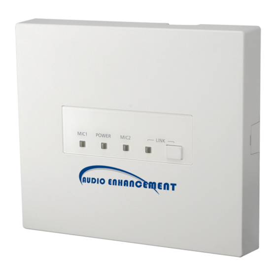
- Page 1 XD Wireless Receiver K-SRC14 | 1.9 GHz 9858 S. Audio Drive, West Jordan, UT 84081 • Phone 1.800.383.9362 • AudioEnhancement.com Rev.2.10...
- Page 2 FCC CAUTION Changes or modifications not expressly approved by the party responsible for compliance could void the user’s authority to operate the equipment. This device complies with part 15 of the FCC Rules. Operation is subject to the following two conditions: (1) This device may not cause harmful interference, and (2) this device must accept any interference received, including interference that may cause undesired operation.
- Page 3 Safety precautions WARNING: - The main plug or an appliance coupler shall remain readily operable. - To prevent injury, this apparatus must be securely attached to the floor/wall in accordance with the installation instructions. - The connections should comply with local electrical code. - The installation shall be carried out in accordance with all applicable installation rules.
- Page 4 CONTENTS Important safety instructions ....................... 5 Major operating controls and their functions ................6 Pairing registration of the microphone to a receiver ..............9 Classroom Audio ........................10 Alert message and sound at E2 ....................10 Link error between WAP and the receivers ................10 Functions ..........................
- Page 5 Important safety instructions 1) Read these instructions. 2) Keep these instructions. 3) Heed all warnings. 4) Follow all instructions. 5) Do not use this apparatus near water. 6) Clean only with dry cloth. 7) Do not block any ventilation openings. Install in accordance with the manufacturer's instructions. 8) Do not install near any heat sources such as radiators, heat registers, stoves, or other apparatus (including amplifiers) that produce heat.
- Page 6 Major operating controls and their functions [1] [LINK] button Pressing this button will put the receiver into register mode to pair with a microphone. (This register mode is canceled after 20 seconds) Refer to operating procedures (At the time of E2 state, the button operation is invalid) [2] [POWER] POWER indicator (Green/Yellow/Red) This LED lights green when the power is on and this unit can receive signals under normal conditions.
- Page 7 [5] Control terminals 8-pin and 7-pin Euro blocks are used. The following terminals are equipped. E1 CNT: provides E1 signal * output controlled by K-STD14 (Teacher Microphone). E2 CNT: provides E2 signal * output controlled by K-STD14. * Those are available when K-STD14 is used. Settings of E1 and E2 are performed with K-STD14. E2 ACK: connects acknowledge signals responding to E2 output.
- Page 8 Operating procedures A standard CAT5 or CAT5e cable is used to connect to the amplifier. Turn on the amplifier. The POWER LED of the receiver lights green. 2. Power ON the microphone. [K-STD14]: Press and hold the [PWR/MUTE] button for one second. [K-SHH14]: Push [TALK] button or flip up the [TALK] switch.
- Page 9 Pairing registration of the microphone to a receiver When pairing a new microphone to a receiver, follow this procedure. (Only the Alert Notification Button operates without first pairing the microphone) [LINK] button [REC] button [PWR/MUTE] button [LINK] button Press a receiver's [LINK] button, and the receiver is put into registration mode. When a LINK button is pressed, the LINK LED blinks yellow for 20 seconds (pairing registration mode) During this time, please use the following instructions to pair your microphones.
- Page 10 Classroom Audio Teacher Microphone [K-STD14] Pressing the [PWR/MUTE] button for one second or more will power up the microphone. The microphone can be used in a classroom. (When paired, MIC1 or MIC2 LED indicator lights green on the receiver) Note: •...
- Page 11 Functions Microphone override function ● This is a function where the audio level of LINE IN automatically lowers when the audio input of the microphone MIC1 or microphone MIC2 is provided. The attenuation of the audio level is –12 dB. When the audio input of the MIC1 or MIC2 is no longer provided, the volume of LINE IN automatically returns to the previous level.
- Page 12 E1 CNT, E2 CNT function ● These functions are available when the K-STD14 microphone is used. When E1 or E2 is controlled with the microphone, control signals are provided from the E1 CNT or E2 CNT terminal of this unit. Selection between E1 and E2 is made at the microphone side.
- Page 13 LED lighting indication LED lighting indication 1 [POWER/MIC1/MIC2] The three LEDs of this unit act as a status indicator, indicating signal reception. Those LEDs indicate the operating states as shown in the table. Furthermore, the priority order of the indications is dependent on operating states.
- Page 14 LED Indication 2 [LINK LED] When a LINK key is pressed, the LINK LED blinks yellow for 20 sec (pairing registration mode) ・LED color will change according to priority. Shown below: LED indication Status LINK It has been unable to register with the or System error In pairing registration Blink yellow at 500 ms period (for...
- Page 15 DIP switch setting Default setting Switch1 Switch2 switch Name Function Switch1 MIC OVERRIDE Selection of microphone override function Deactivated Activated* Selection of tone signal from this unit at TONE ON/OFF Tone OFF Tone ON* operating volume button of K-STD14 Selection of tone signal (2 levels) at operating Tone Level H-L Low level* High level...
- Page 16 Note: The settings of these switches are updated when the receiver boots up. Settings changed while powered on are not updated until the receiver is restarted. (Excluding No.7 of DIP Switch 1) Dip switch2-8[ON]: If the RCV disconnects from the WAP, the RCV will reboot automatically and try to reconnect with the WAP. No.
- Page 17 Rev.2.10...
- Page 18 Connections Connection of receiver ■ LINE IN connection ● Connect the audio output of a projector, CD player or DVD/VCR or similar line level output to the LINE IN connector of this unit. The line input of this terminal is a stereo input. Audio signals are mixed to monaural signals internally. Cables should be selected depending on the connector type of the media device.
- Page 19 AUDIO OUT connection ● Connect the audio input of a network camera or similar level input to the AUDIO OUT connector of this unit. The line output of this terminal is a mono output. Cables should be selected depending on the connector types of devices to be connected and follow the description below to connect external devices.
- Page 20 Connection of E1 CNT and E2 CNT terminals ● An external device is connected between CNT and COM. These terminals are isolated from the internal circuit by a photo coupler. E1 CNT E2 CNT E2 Com E2 Cont E1 Com E1 Cont Connection of E2 ACK, PAGE MUTE, LINK BUTTON and ALERT BUTTON terminals ●...
- Page 21 Connection of RS-232C ■ The K-SRC14 receiver can send and receive commands and status information via RS-232C to external devices. The external device is connected with a 3-wire cable. The cable should be cross-connected, in other words, the transmitting signal (TxD) of this unit is connected to the receiving signal (RxD) of the external device, and the receiving signal (RxD) of this unit is connected to the transmitting signal (TxD) of the external device.
- Page 22 Precautions for installation The installation should be carried out following local standards for electrical products. Warning • Be sure to contact your dealer for installation. Before installing, turn off the power of the connecting product. In addition, be sure to read these "Precautions" and safety precautions on page 3 carefully and follow the instructions.
- Page 23 Installation Warning • Before installing, be sure to turn off the power of the receiver. There is a risk of electric shock. Installation of the receiver ■ When using a ceiling panel ● When installing the receiver and cables in a removable ceiling, follow the instructions below. 1) Make a hole in the ceiling panel Remove the ceiling panel, drill a hole of approx.
- Page 24 Step 1 Mounting bracket AE plate Ceiling Panel Screw cover Step 2 Screwdriver Rev.2.10...
- Page 25 When mounting on a wall ● When installing the receiver and cables to a removable wall, follow the instructions shown below. 1) The mounting bracket is fixed to a wall with a screwdriver using a provided screw. Note: • Fix this unit firmly with specified torque with a tool such as a torque driver. 2) Connect the necessary cables to the receiver.
- Page 26 Step 1 Mounting bracket Step 2 Screw cover Step 3 Screwdriver Rev.2.10...
- Page 27 Serial communication command Serial communication command Preface ■ Use of the serial command allows the volume of this unit and settings of functions (page 13) with the DIP switch to be an external device remotely controlled. Note: • The settings of the functions that can be set with the DIP switch can be overwritten by sending a serial command. The serial command has the higher priority and will override the DIP switch settings.
- Page 28 Rev.2.10...
- Page 29 Command List Command Content Type 1st parameter 2nd parameter Command example Query None None $QPW[CR][LF] Query about this unit power state Response 1: POWER ON None $QPW:1[CR][LF] Notification of Change 1: MIC1 input 0: MIC OFF microphone power $CCS:1:1[CR][LF] notification 2: MIC2 input 1: MIC ON state...
- Page 30 Command Content Type 1st parameter Command example parameter 0: Disable Setting 2: Tone $SDS:2:1[CR][LF] 1: Enable Tone setting Same as Response Same as above $SDS:2:1[CR][LF] above 0: Low, 1: Setting 3: Tone Level $SDS:3:0[CR][LF] Tone Level High setting Same as Response Same as above $SDS:3:0[CR][LF]...
- Page 31 Receiver (XD Microphone (XD XD ID (20 Change XD ID (20 bits) is bits) is notification of specified by the specified by Change microphone character string the character $CMI:12345:23456[CR][LF] notification ID registration (5 bytes) of a string (5 hexadecimal bytes) of a form.
- Page 32 XD ID (20 bits) is specified by the character string (5 bytes) of a hexadecimal form. Parameter3 Paring status bit: The connection state of Microphone and Receiver before activating an Alert. 0 = not paired, 1 = paired Parameter4 RF signal strength: 0-63 is specified by It is a linear value showing signal strength.
- Page 33 Troubleshooting Symptom Cause/solution Does the POWER LED light? >> Check the connection between the receiver and the amplifier. Check the power of the amplifier is turned on No reception Is the power of the microphone turned on (Is a battery loaded)? >>...
- Page 34 Specifications General Power (DC IN) 24 VDC (minimum 21.6 VDC ~ maximum 26.4 VDC) input by Amplifier. Input current 130 mA Operating temperature range 0°C - 40°C {32°F - 104°F} Dimensions 7.28" (W) x 6.3" (H) x 1.26" (D) (185 mm (W) x 160 mm (H) x 32 mm (D)) Mass 0.72 lbs.
- Page 35 Mounting bracket: 1 Tie for cable: 2 Screw: 1 Leaflet: 2 ( Safety precautions, open software license) Unattached: Operating Instructions: None. Total operating instructions are prepared by Audio Enhancement. Warranty Card: None, the warranty period is described in the contract. Rev.2.10...
Need help?
Do you have a question about the K-SRC14 and is the answer not in the manual?
Questions and answers