Table of Contents
Advertisement
Advertisement
Table of Contents

Subscribe to Our Youtube Channel
Related Manuals for Jenoptik LDM51 Series

Summary of Contents for Jenoptik LDM51 Series
- Page 2 OPTICAL SYSTEMS I LASERS & MATERIAL PROCESSING I INDUSTRIAL METROLOGY I TRAFFIC SOLUTIONS I DEFENSE & CIVIL SYSTEMS Laser Measuring Module LDM52_OEM Operating Manual...
- Page 4 No part of this manual may be reproduced in any form (photograph, photocopy, microfilm or any other procedure) without the prior written permission of JENOPTIK Advanced Systems GmbH, nor may contents be processed, reproduced or distributed using electronic systems . This operating manual was produced with the appropriate care.
-
Page 6: Table Of Contents
Table of contents OVERVIEW ......................... 7 Symbols and references ....................7 Warning signs ......................7 General information ....................7 SAFETY ADVICE......................8 Basic safety advice ..................... 8 Laser class ........................9 Transport and storage ....................9 Cleaning and maintenance ..................9 Service ........................ - Page 7 Table of contents 6.4.8 OF – Offset ......................23 6.4.9 PA – Parameter setting .................... 24 6.4.10 PR – Parameter setting ..................25 6.4.11 SA – Average value .................... 26 6.4.12 SB – Stop bit of the serial output ................ 26 6.4.13 SD –...
-
Page 8: Overview
1.3 General information The laser distance meters of the LDM51 series have been designed for application in industrial facilities. Within the measuring range of 15 cm to 200 m the sensors work with a high accuracy of up to + 1 mm and at a variably adjustable measuring frequency of maximally 100 Hz. -
Page 9: Safety Advice
Safety advice 2 Safety advice 2.1 Basic safety advice Please read the safety and operating advice carefully, and observe the advice when operating the LDM52 OEM laser distance measurement device. Danger, laser radiation The LDM52 OEM must not be taken apart unauthorized, otherwise laser radiation can be emitted that can cause injuries to the eyes. -
Page 10: Laser Class
Mechanical or electrical modifications of the device are not permitted. 2.5 Service In case that repair work is necessary, please send the device to the address below: JENOPTIK I Defense & Civil Systems JENOPTIK Advanced Systems GmbH BU Sensors / Service Department... -
Page 11: Intended Use
Intended use 3 Intended use 3.1 Operating and storage conditions Operating temperature - 10 °C … + 40 °C Storage temperature - 40 °C … + 70 °C Humidity 15% … 60%, non-condensing The LDM52 OEM has to be used in a closed housing only. 3.2 Improper use and possible error sources ... -
Page 12: Warning Signs And Type Plates
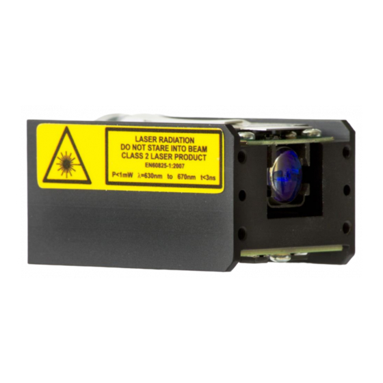
Intended use 3.3 Warning signs and type plates Laser label 655 nm einfügen The LDM52 OEM works with a class 2 laser. When looking into the laser beam accidentally and for a short moment, the eye will be protected by the eyelid clos- ing reflex. -
Page 13: Device Description
Device description 4 Device description 4.1 Scope of delivery Designation Part no. LDM51_Measuring Module OEM 012890-400-22 PLease use following reflection foils for long range measurements: Designation Part no. Remarks 300 mm x 300 mm Reflective tape Oralite 5200, 300x300 012890-001-28 measurements from as low as 50 m 1 m x 1 m Reflective tape Oralite 5200, 1000x1000... -
Page 14: Device Cable Connector Pin Assignment
Device description Device cable connector pin assignment Signal Description Power 5 + 0.5 V DC RS232 TxD: level 3,3V CMOS Ground RS232 RxD: level 3,3V CMOS Ground Switching output Q1: level 3,3V CMOS Ground Switching output Q2: level 3,3V CMOS Ground Switching output Q3: level 3,3V CMOS Ground... -
Page 15: Laser Beam Image
Device description 4.4 Laser beam image The laser beam of the LDM52 OEM has a divergence of 0.13 mrad x 0.17 mrad (width x height). The diameter of the laser spot on the exit lens measures 4 mm. The table below shows the size of the laser spot in dependence on the distance. The laser spot has an elliptical shape. -
Page 16: Installation And Commissioning
Installation and commissioning 5 Installation and commissioning 5.1 Commissioning Remove the packaging of the LDM52 OEM. Check the delivery for completeness. Examine the device and the accessories for damage. The delivery is without connecting cable. If the LDM52 OEM should be operated as a stand alone unit a service cable must be prepared which supplies the LDM52 OEM with voltage and connects the unit to PC (e.g.USB). -
Page 17: Parameter Setup And Measuring Operation
Parameter setup and measuring operation 6 Parameter setup and measuring operation 6.1 General information The LDM52 OEM is parameterized using the serial interface. Precondition for programming via serial interface is a connection provided by a terminal program (e.g. HyperTerminal --> see chap- ter 7). -
Page 18: Measurement Involving Moving Targets
Parameter setup and measuring operation 6.2 Measurement involving moving targets Where measurements involve a moving object or the LDM52 OEM is moved during measuring, this will have an impact on the accuracy of the measured value. This must be observed particularly when calculating average values (parameter SA). Measurement jumps and/or considerable changes in the reflectivity of the target surface can pro- long the measurement period. - Page 19 Parameter setup and measuring operation - Prints the temperature of the device. - Prints all parameters. - Resets the parameters to firmware defaults. SA (%u) - Prints/Changes average. Co-domain: [1, 50]. MF (%f) - Prints/Changes measurement frequency. Co-domain: [0.0, 100.0], (0 == auto). MW (%u %u) - Prints/Changes the expected ranged for measurements in 'mm / 10'.
-
Page 20: Status
Parameter setup and measuring operation 6.4 Status 6.4.1 AS – Autostart The autostart function defines the behavior of the LDM52 OEM after a cold boot. After the connection to the supply voltage and the internal start-up routine the LDM52 OEM will automatically execute the command and send the data to the available outputs. -
Page 21: Br - Baud Rate
Parameter setup and measuring operation 6.4.2 BR – Baud rate BR enables the adjustment of the serial baud rate x. As soon as a new baud rate is set, the device will start communicating with the new baud rate. BR will not be modified upon a parameter reset via PR. Query: Set: Range of parameter x:... -
Page 22: Mct - Output/ Modification Of The Operating Mode When Starting A Measurement Using The Display
Parameter setup and measuring operation 6.4.4 MCT – Output/ modification of the operating mode when starting a measure- ment using the display When starting a continuous measurement using an external display, you need to define if the LDM52 OEM should measure based on the operating mode DT or CT. The operating mode is selected via the command MCT. -
Page 23: Mun - Unit Of The Measured Value
Parameter setup and measuring operation 6.4.6 MUN – Unit of the measured value MUNx enables the definition of a unit for the output value. It is shown together with the meas- ured value. In order to use MUN, SF 0 must be set. Query: Set: MUNx... -
Page 24: Of - Offset
Parameter setup and measuring operation 6.4.8 OF – Offset OF parameterizes an user-specific offset x that is added to the measured value. It is entered in 0.1 mm. Query: Set: Range of parameter x: -5000000 ….5000000 Standard: Output: Offset in 'mm / 10' [OF]: 0 The LDM52 OEM does not check the set offset for plausibility. -
Page 25: Pa - Parameter Setting
Parameter setup and measuring operation 6.4.9 PA – Parameter setting Output of a parameter list with the current settings Query: Output: Baudrate of serial port [BR]: 115200 Stopbits of serial port [SB]: Average [SA]: Measurement frequency [MF]: Minimum distance from target [MW]: -5000000 Maximum distance from target [MW]: 5000000... -
Page 26: Pr - Parameter Setting
Parameter setup and measuring operation 6.4.10 PR – Parameter setting Resetting of all parameters to factory settings (default values) The following parameters are not reset by entering PR: Baud rate Serial port Stop bits Setting parameters for serial interface Input: Output: Parameters set to firmware defaults. -
Page 27: Sa Average Value
Parameter setup and measuring operation 6.4.11 SA – Average value SA parameterizes the number x of the individual measured values to be averaged for measured value output. SA directly correlates with the measuring frequency MF. SA and MF determine the output frequency for the measured values. Query: Set: Range of parameter x:... -
Page 28: Sd - Data Format Of The Serial Interface Output
Parameter setup and measuring operation 6.4.13 SD – Data format of the serial interface output SD parameterizes the output format and the possible output values. The following outputs are possible: Distance Signal quality Temperature Switching outputs (active/ inactive) Query: Set: SDw x y z... - Page 29 Parameter setup and measuring operation Parameter Value Signal quality Temperature Switching outputs Data format SD - Binary format: Distance: 4 Byte, MSB = Bit 31 MSB of Byte 3 always 1 MSB of Byte 2, 1 and 0 always 0 Measurement data of each Byte = Bit 6 …...
-
Page 30: Se - Error Mode
Parameter setup and measuring operation For parameterizing of switching outputs see chapter 6.6 6.4.14 SE – Error Mode Parameterizes the behavior x of switching outputs Q1, Q2, Q3, of the analog output QA and an external SSI Interface in case of faulty measurements as well was the condition upon execution of an individual distance measurement Query: Set:... -
Page 31: Sf - Scale Factor
Parameter setup and measuring operation 6.4.15 SF – Scale factor SFx defines a factor by which the output value is multiplied. Query: Set: Range of parameter x: -10.000 …. 10.000 Standard: Output: Scale factor [SF]: 0.000 At SF ≠ 0 the parameter MUN is ineffective. At SF = 0 the unit defined by MUN becomes effective. -
Page 32: Sp - Separator For Parameters
Parameter setup and measuring operation 6.4.17 SP – Separator for parameters Output values are separated by the character SP. Query: Set: Range of parameter x: 1 … 5 Standard: Output: Separator [SP]: 0x2C Value x Symbol ASCII Comma 0x2C Semicolon 0x3B Space 0x20... -
Page 33: Tp - Internal Temperature
Parameter setup and measuring operation Value selection: ASCII Meaning 0x0D0A CR LF 0x0D 0x0A 0x02 0x03 0x09 Htab (Tabulator) 0x20 Space 0x2C Single Quote 0x3A Colon 0x3B Semicolon When an invalid character is entered, it will not be set. The current separator will be kept instead. -
Page 34: Additional Commands
Parameter setup and measuring operation 6.4.20 Additional commands Command Description Switches off the laser diode Switches on the laser diode SDT or ESC-Taste Deactivates the continuous measurement mode Switches off the heating until restart (available only in devices that are equipped with a heating element) Output of device temperature Executes a restart (does not reset the parameters;... -
Page 35: Operating Modes
Parameter setup and measuring operation 6.5 Operating modes 6.5.1 DM – Individual distance measurement The LDM52 OEM will perform exactly one measurement and then wait for new instructions. The duration of the measurement depends on the number of preset measuring values SA and the preset measuring frequency MF. - Page 36 Parameter setup and measuring operation Remarks: In case of poor target reflectivity, it cannot be guaranteed at 100 % that the respective measure- ment will be completed within the available time. If the time between 2 measurement outputs is too short a warning will be generated (-->...
-
Page 37: Ct - Continuous Tracking
Parameter setup and measuring operation Operation Mode DT Target Measu- Measuring range* Accuracy Repealibility ring (Standard devi- fre- ation) quency variabel 15 cm … 100 m + 2,5 mm + 1,0 mm white, matt, reflectivity approx. 80 % 20 Hz 15 cm …... - Page 38 Parameter setup and measuring operation Areas of application: Scanning of static targets. Quick measurements on hot surfaces. Tracking of continuously quickly moving targets (e.g. crab [crane], vehicle) Distance jumps or laser beam interruptions can result in faulty measurements! The warning w1912 is issued.
-
Page 39: Q1/Q2/Q3 - Switching Output
Parameter setup and measuring operation 6.6 Q1/Q2/Q3 – Switching output The switching outputs Q1, Q2 and Q3 show distance information as logic switching information. They signalize when values are above or below a preset switching range subject to hysteresis. Hence, they are perfectly suitable for the direct further processing of monitoring variables such as filling level or object detection. - Page 40 Parameter setup and measuring operation Parameter Description Spezification Switching threshold (in 0.1 mm); 32 bits integer activate switching status z from this distance Switching range (in 0.1 mm); 32 bits integer a range of x µm from w Switching hysteresis (in 0.1 mm); 32 bits integer length of the tolerance range y >...
-
Page 41: Qa - Analog Output
Parameter setup and measuring operation 6.7 QA – Analog output The analog output enables the normed, analog transmission of distance data across large dis- tances using a two-wire line. The current of 4...20 mA impressed in the line is proportional to the measured distance within an adjustable distance interval. - Page 42 Parameter setup and measuring operation Value Description Specification Lower limit x ≠ y y ≠ x Upper limit Input of parameter QA in 0.1 mm. Input: QA10000 150000 Output: Parametrization of the analog switching output QA [QA]: 10000, 150000 The value of the output current (in mA) is calculated as follows: ...
-
Page 43: Tri + Tro Trigger
Parameter setup and measuring operation 6.8 TRI + TRO Trigger 6.8.1 Trigger function The LDM52 OEM Trigger could be used as input or output. 1. Trigger input / external trigger function: External trigger signal will be sent → start of measurement DM in accordance with parame- ter TRI. -
Page 44: Tri - Trigger Input
Parameter setup and measuring operation 6.8.2 TRI – Trigger input The parametrization of trigger input will be set with command TRI. edge parameterized the edge of trigger signal rising edge (from LOW to HIGH) falling edge (from HIGH to LOW) every edge delay parameterized the time (delay) up to the measurement in milliseconds msec... -
Page 45: Tro - Trigger Output
Parameter setup and measuring operation 6.8.3 TRO – Trigger output The parametrization of trigger output will be set with command TRO. edge parameterized the edge of trigger signal rising edge (from LOW to HIGH) falling edge (from HIGH to LOW) every edge delay parameterized the time (delay) up to the measurement in milliseconds msec... -
Page 46: Serial Interface And Communication Software
Serial interface and communication software 7 Serial interface and communication software 7.1 Transmission protocol Interface settings: Asynchronous, 8 data bits, no parity, 1 stop bit Transmission protocol format / syntax: 7 bit ASCII Proprietary transmission protocol Commands are case-insensitive (NO differentiation between lower and upper case). -
Page 47: Installation Of The Communication Program
Serial interface and communication software 7.2 Installation of the communication program HyperTerminal is a terminal program generally included in Win32 operating systems. It can be used as a communication program to parameterize the LDM52 OEM. Start HyperTerminal via the following menu path: |Start | Programs | Accessories | Communication | HyperTerminal| Enter the name of the new connection in the dialog box. - Page 48 Serial interface and communication software At this point, baud rate (bits per second) and flow control must be initialized cor- rectly. As soon as the settings in the third dialog box are confirmed with [OK], the terminal window will open. The status indication in the left bottom corner reads “Connected”...
- Page 49 Serial interface and communication software |File | Properties | Settings | |ASCII-configuration...| |Inpu translation … Please note: Do not tick the check box “Sent lines end with line feed”. End the session with |File | Quit|. LDM52 OEM, Release 003, Revision 000...
- Page 50 Serial interface and communication software A small window will appear where you are asked if the connection should really be termi- nated. This question must be responded to by pressing the [Yes] button. If the current HyperTerminal session has not been saved yet, a small window will appear where you are asked if the session should be saved.
-
Page 51: Error Processing
Error processing 8 Error processing In case of errors or when a measured value cannot be determined or put out, a warning or an error message will be displayed. Error Meaning Action e1001 Error operation system/ firmware e1002 Error operation system/ firmware Restart system e1003 Error operation system/ firmware... -
Page 52: Technical Data
Technical Data 9 Technical Data Measurement properties Measurement principle Pulse reflection mixing method Measured parameter Distances Measuring range 0.15 m … 200 m Total 50 m … 200 m Onto Oralite 5200 target board 0.15 m … 100 m Onto Oralite special target board Onto natural surfaces, 80% remission 0.15 m …... - Page 53 Technical Data Environmental and application conditions Operating temperature of LDM52 OEM -10 °C … + 60 °C Storage temperature -40 °C … + 70 °C Humidity 15 % … 60 %, non-condensing Dimensions 50 mm x 35 mm x 27 mm (LxWxH) Weight approx.
- Page 54 User Notes --- Nachfolgende Absätze (rote Absatzendemarken) nicht löschen / im Rahmen verstecken Ü...
Need help?
Do you have a question about the LDM51 Series and is the answer not in the manual?
Questions and answers