
Related Manuals for BRINKMANN PUMPS Bplogic

Summary of Contents for BRINKMANN PUMPS Bplogic
- Page 1 Operating manual Intelligent pump controller Bplogic Please read this manual prior to starting any work!
- Page 2 1 Overview Brinkmann Pumpen K.H. Brinkmann GmbH & Co. KG Friedrichstr. 2 58791 Werdohl GERMANY +49 2392 5006-0 sales@brinkmannpumps.de www.brinkmannpumps.de BRIN-46069-EN, Version 03.01, en_UK © Brinkmann Pumpen 2021 bplogic intelligent pump controller 18/02/2021...
-
Page 3: Table Of Contents
Modbus RTU ............... 35 3.2.8 Supported bus protocols ............. 35 3.2.9 Connections and interfaces ..........36 3.2.10 Automatic and manual mode ..........38 4 Installing the pump controller ............... 39 Fitting the pump controller ............... 39 18/02/2021 bplogic intelligent pump controller... - Page 4 Executing control mode with one pump ......103 5.4.3 Parallel mode ..............105 5.4.4 Saw tooth cycle mode ............109 5.4.5 Pressure increase.............. 115 5.4.6 Logic module ..............117 Secondary functions ..............157 5.5.1 Offset control ..............157 bplogic intelligent pump controller 18/02/2021...
- Page 5 Backing up and updating application modules ....250 7.2.3 Backing up and updating the system software ....253 7.2.4 Backing up and updating settings ........256 Event messages ................259 7.3.1 Layout of an event message ..........259 18/02/2021 bplogic intelligent pump controller...
- Page 6 9 Storage, transport, dismantling and disposal ........279 Storage and transport ..............279 Dismantling and disposal ............... 279 10 Licensing information ................281 11 EC Declaration of Conformity .............. 282 12 Accessories and required materials ........... 284 13 Index ...................... 285 bplogic intelligent pump controller 18/02/2021...
-
Page 7: Overview
This operating manual (subsequently referred to as “Manual”) contains impor- tant information that must be observed when installing, operating and maintain- ing the bplogic intelligent pump controller (subsequently referred to as “pump controller”). This operating manual must therefore be read by the electricians and the responsible technical personnel/owner prior to assembly and commis- sioning and must always be available at the pump controller’s operating loca-... - Page 8 And/or: Have the pump controller’s order number and serial number at hand. Address Brinkmann Pumpen K.H. Brinkmann GmbH & Co. KG Friedrichstr. 2 58791 Werdohl GERMANY Phone +49 2392 5006-0 E-mail sales@brinkmannpumps.de Internet www.brinkmannpumps.de bplogic intelligent pump controller 18/02/2021...
-
Page 9: General Description Of The Intelligent Pump Controller
Various I/O modules can be in- serted into the I/O level and therefore connected to the main circuit board. The service access (Fig. 1/2) is located on one of the two short device sides. 18/02/2021 bplogic intelligent pump controller... -
Page 10: Pump Tasks And System Integration
PROFINET IO field bus can be used additionally on a pump controller with the PROFINET option. The pump controller is delivered preconfigured for the complete installation into which it is integrated. After assembly, you only have to set parameters for func- tions and settings. bplogic intelligent pump controller 18/02/2021... - Page 11 1 Overview Supported frequency converters Brinkmann Danfoss Emotron Fuji Electric Kostal Mitsubishi 18/02/2021 bplogic intelligent pump controller...
-
Page 12: Safety
NOTICE! This combination of symbol and signal word advises of a possibly dangerous situation that may cause damage to property if not avoided. bplogic intelligent pump controller 18/02/2021... - Page 13 Screen elements (e.g. on-screen buttons, alloca- tion of function keys) Safety instructions in handling instructions Safety instructions can refer to specific, individual handling instructions. These safety instructions are embedded into the handling instruction so that they do 18/02/2021 bplogic intelligent pump controller...
-
Page 14: Proper Use
Proper use also includes adhering to all specifications in this operating manual. Any use that differs from or goes beyond proper use is considered misuse. bplogic intelligent pump controller 18/02/2021... -
Page 15: Safety Equipment
Each system component can pose hazards. The system owner is responsible for checking whether using the pump controller would make further safety equipment necessary, such as using a safety control system. 18/02/2021 bplogic intelligent pump controller... -
Page 16: Residual Risks
For more information, see the further applicable documents ( “Further applicable documents” on page 7), especially: Documentation for the machines, actuators, sensors and safety equipment in the complete installation. Owner operating instructions. bplogic intelligent pump controller 18/02/2021... - Page 17 Ensure that the 24 V power supply meets the requirements of protective extra-low voltage (PELV) or safety extra-low voltage (SELV protection class III). The electrical connection may only be established by an electrician. 18/02/2021 bplogic intelligent pump controller...
- Page 18 Section 8.3 “Electrical properties” on page 272 Section 8.3.2 “I/O module 1” on page 273 Section 8.3.3 “I/O module 2” on page 275 The electrical connection may only be established by an electrician. bplogic intelligent pump controller 18/02/2021...
-
Page 19: Owner Responsibility
The owner is the person who operates the pump controller and the complete installation for commercial or economic purposes themselves or contracts a third party to use/operate it, and who bears the legal product responsibility for protecting the user, the staff or third parties during operation. 18/02/2021 bplogic intelligent pump controller... - Page 20 The owner must ensure that the maintenance intervals described in this operat- ing manual and the further applicable documents are adhered to. The owner must have all safety equipment checked on a regular basis to en- sure that it is functioning and complete. bplogic intelligent pump controller 18/02/2021...
-
Page 21: Staff Requirements
Only people who can be expected to perform their work reliably are permitted to be employed as staff. People with impaired reactions, e.g. due to drugs, alcohol or medication, are not permitted. 18/02/2021 bplogic intelligent pump controller... - Page 22 The commercial owner must instruct the staff on a regular basis. A training log with at least the following content must be created for better tracking: Date of training Name of trainee Contents of training Name of trainer Signature of trainee and trainer bplogic intelligent pump controller 18/02/2021...
-
Page 23: Personal Protective Equipment
Safety shoes Safety shoes protect the feet against crushing, falling parts and slipping on slippery surfaces. There may be other requirements depending on the installation location and the complete installation, such as wearing a hard hat. 18/02/2021 bplogic intelligent pump controller... -
Page 24: Environmental Protection
Have packaging materials that are no longer required recycled or disposed of in an environmentally friendly manner. Observe the locally applicable disposal regulations. If in doubt, commission a specialist company with disposal. bplogic intelligent pump controller 18/02/2021... -
Page 25: Pump Controller Fields Of Application And Layout
Maximum of 6 application modules (more upon request) Application modules: Adjustment mode Control mode Parallel mode Pressure increase Saw tooth cycle mode Logic module Maximum of 6 frequency converters (more upon request) 18/02/2021 bplogic intelligent pump controller... -
Page 26: Pump Controller Layout
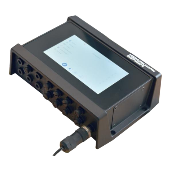
3 Pump controller fields of application and layout Pump controller layout Pump controller overview Fig. 2: Overview (sample configuration) Housing I/O level/slot C Holes for fastening screws Touchscreen I/O level/slot A Service access (open) I/O level/slot B bplogic intelligent pump controller 18/02/2021... -
Page 27: Housing
All housing openings are sealed. Sealing caps are supplied to cover any un- used M12 connections. Any unused slots on the I/O level are sealed with a blanking plate. When protected in such a fashion the housing has protection category IP65. 18/02/2021 bplogic intelligent pump controller... -
Page 28: Touchscreen
The operating system can be stored on the pump controller’s internal flash memory or on external storage media. The boot sequence is as follows: external USB storage medium external micro SD card internal eMMC memory bplogic intelligent pump controller 18/02/2021... -
Page 29: I/O Level Slots
I/O modules into the intended slots carefully. En- sure that you do not injure yourself on the pointed pin bars. I/O modules may only be inserted into/removed from the pump controller by an electrician. 18/02/2021 bplogic intelligent pump controller... -
Page 30: I/O Modules And Slot Allocation
4 switchable digital inputs/outputs and one analog input and out- put each. In order to maintain the IP65 level of protection, the unused M12 connections must be sealed with the sealing caps provided. bplogic intelligent pump controller 18/02/2021... - Page 31 On 6 M12 connections (X1 to X6), one I/O module 2 provides 2 digital and ana- log inputs, 4 digital outputs and one analog output. In order to maintain the IP65 level of protection, the unused M12 connections must be sealed with the sealing caps provided. 18/02/2021 bplogic intelligent pump controller...
- Page 32 If actuators with a high current requirement are to be supplied, this can be performed by a second 24 V power supply. bplogic intelligent pump controller 18/02/2021...
-
Page 33: Usb And Micro Sd
USB dongles may only protrude by a maximum of 1.5 cm when plugged in so that the cover on the service access can be closed. A micro SD card (up to 32 GB capacity, Fig. 9/3) can also be inserted to in- crease the memory. 18/02/2021 bplogic intelligent pump controller... -
Page 34: Ethernet
As the cover on the service access has to be opened in order to use this feature, housing protection level IP65 is sacrificed by this until the service access is closed again properly. The ETH 1 and ETH 2 ethernet interfaces are not switched. bplogic intelligent pump controller 18/02/2021... -
Page 35: Modbus Rtu
Field bus, each with M12 connection (A-coded): Modbus RTU CAN and CANopen upon request Real-time ethernet, each with M12 connection (D-coded): PROFINET RT EtherNet/IP other field buses upon request 18/02/2021 bplogic intelligent pump controller... -
Page 36: Connections And Interfaces
Design the 24 V power supply as protective extra-low voltage (PELV) or safety extra-low voltage (SELV protection class III). 3.2.9.2 Power supply for actuators, sensors and logic Fig. 12: Connection diagram for sensors and actuators bplogic intelligent pump controller 18/02/2021... - Page 37 Ensure that the maximum permissible rated current of 14 A is not exceeded. For the connection values, see: Section 8.3 “Electrical properties” on page 272 Section 8.3.2 “I/O module 1” on page 273 Section 8.3.3 “I/O module 2” on page 275 18/02/2021 bplogic intelligent pump controller...
-
Page 38: Automatic And Manual Mode
Standard mode Use automatic mode! Automatic mode is the pump controller’s standard mode. Only use manual mode for installation, commissioning or trouble- shooting. bplogic intelligent pump controller 18/02/2021... -
Page 39: Installing The Pump Controller
271), particularly the permissible temperatures for op- erating the pump controller (-20 °C – 55 °C). Do not expose the pump controller to direct sunlight. If there is a risk of overheating, ensure that fresh air supply/ventilation is available. 18/02/2021 bplogic intelligent pump controller... - Page 40 Pay attention to the latest state of technology, as well as the current accident prevention regulations when installing and re- moving the pump controller. When drilling the fastening holes to install the pump controller, ensure that the required protective equipment is used. bplogic intelligent pump controller 18/02/2021...
-
Page 41: Network Topologies
Section 4.3.2.1 “I/O module 1 connection diagram” on page 46 and section 4.3.2.2 “I/O module 2 connection diagram” on page 47 Pump controller Control line 2 Modbus Section 4.3.2.3 “Power module connection diagram” on page 49 Pump/frequency converters 18/02/2021 bplogic intelligent pump controller... -
Page 42: Connecting The Pump Controller Electrically
1 (Fig. 15/A) and one I/O module 2 (Fig. 15/B). Slot C always contains the same power module (Fig. 15/C). If a slot is not allocated due to a special configuration, it is sealed using a cover plate. bplogic intelligent pump controller 18/02/2021... -
Page 43: Connecting I/O Modules
12-pin M12 connection for I/O module 1 in slot A 5-pin M12 connections for I/O module 2 in slot B 4.3.2 Connecting I/O modules Manufacturer’s assembly staff Staff: Electrician Service access cover Materials: M12 sealing caps 18/02/2021 bplogic intelligent pump controller... - Page 44 Danger of electric shock due to improper power supply! The electrical connection may only be established by an electrician. The 24 V power supply must meet the requirements of protective extra-low voltage (PELV) or safety extra-low voltage (SELV protection class III). Connect- bplogic intelligent pump controller 18/02/2021...
- Page 45 49 Cover unused connections with the enclosed M12 sealing caps in order to ensure the housing’s protection class. Install the safety equipment in accordance with the “Further applicable documents” on page 7. 18/02/2021 bplogic intelligent pump controller...
- Page 46 Pin 4 Digital in 4 Pin 5 Digital in 5 Pin 6 Digital in 6/Digital out 1 Pin 7 Pin 8 Analog out 1 Pin 9 Analog in 1 Pin 10 Digital in 7/Digital out 2 bplogic intelligent pump controller 18/02/2021...
- Page 47 Fig. 17: I/O module 2 connection diagram Functional earth is connected to PIN 5 and the shielding of each M12 connec- tion. Also observe the special documentation for information on con- necting the sensors and actuators. 18/02/2021 bplogic intelligent pump controller...
- Page 48 Actuator – – – Digital Digital Digital Out 2 Out 4 In 2 Observe the connection values: Maximum allowed actuator supply current (total): 1.0 A Maximum allowed sensor supply current (total): 1.0 A bplogic intelligent pump controller 18/02/2021...
- Page 49 The connections for the power supply, network and field bus are allocated as follows: ETH 1: Network Allocation Pin 1 TD+ (transmission data+) Pin 2 RD+ (receiver data+) Pin 3 TD– (Transmission Data–) Pin 4 RD– (Receiver Data–) 18/02/2021 bplogic intelligent pump controller...
- Page 50 (PELV) or safety extra-low voltage (SELV protection class III). Allocation Pin 1 Pin 2 U_LS Pin 3 GND_A Pin 4 GND_LS Pin 5 Also functional earth is connected to the shilding of the M12 connection bplogic intelligent pump controller 18/02/2021...
- Page 51 LS = logic and sensors Observe the connection values: Maximum allowed input current for actuators I : 14 A Amax Maximum allowed input current for logic and sensors I : 4 A LSmax 18/02/2021 bplogic intelligent pump controller...
-
Page 52: Operating The Pump Controller
Observe the following boot sequence when using removable storage devices: external USB storage medium external micro SD card internal flash memory After start-up, the login screen is displayed (Fig. 19). bplogic intelligent pump controller 18/02/2021... - Page 53 5 Operating the pump controller Fig. 19: Login screen Log in to the active pump controller with a user name and password (Fig. 19). User name Password admin admin service service operator operator 18/02/2021 bplogic intelligent pump controller...
-
Page 54: Optional Pump Controller Operation Via Remote Access
If multiple users are logged in to the pump controller at the same time, only the first user that logged in receives write permissions. Only a user with write authorisation can adjust the pump controller’s settings and operate the pump controller actively. bplogic intelligent pump controller 18/02/2021... - Page 55 “webvisu”, an on-screen keyboard opens as soon as you tap an input field. Turn on the pump controller. Use a web browser to call the pump controller’s web address. The login screen is displayed. 18/02/2021 bplogic intelligent pump controller...
-
Page 56: Operating Principles
The web address is opened directly in your web browser. Section 5.6.4 “Setting WLAN module parameters” on page 204. Operating principles 5.2.1 General screen layout All software displays are laid out according to the following principle. Fig. 21: Screen layout bplogic intelligent pump controller 18/02/2021... - Page 57 ( section 5.2.5 Main screen” on page 62). 4 Navigation bar The jump icons in the navigation bar enable you to switch between adjacent displays and menus ( section 5.2.4 “Navigation bar” on page 59). 18/02/2021 bplogic intelligent pump controller...
-
Page 58: Status Bar
The “Event list” button opens the “Event list” menu. 4 “Logged in user” Displays the username of the logged in user display 5 “Date and time” Displays the current date and the current time display bplogic intelligent pump controller 18/02/2021... -
Page 59: Title Bar
All of the main menu level menus ( section 5.2.11 “Main menu overview” on page 83) Configuration ( section 5.2.11.1 “Menu overview for the “Configuration” menu” on page 84) Application overview Pump overview Application oscilloscope Application single view Pump single view 18/02/2021 bplogic intelligent pump controller... - Page 60 Up to 6 pumps can be assigned to an applica- tion module. Fig. 25: Navigation bar for the single views Calls the application single view Calls the pump single views for the pumps that are available bplogic intelligent pump controller 18/02/2021...
- Page 61 Indicates that there is a fault on the pump Yellow Indicates that a pump is in maintenance mode or that the pump may have to be maintained due to wear Inverted colours Marks the current single view 18/02/2021 bplogic intelligent pump controller...
-
Page 62: Main Screen
Fig. 26: Display areas for the single views Left display area Enables settings to be made and pre-set parame- ter values to be checked Right display area Displays information regarding the current status and the pump performance bplogic intelligent pump controller 18/02/2021... - Page 63 Opens the application single view Pressure increase: Indicates that the application module is controlling a pump group with the “Pressure increase” primary function Opens the application single view 18/02/2021 bplogic intelligent pump controller...
- Page 64 For a multiple selection: displays a selectable setting The setting can be deselected by tapping Indicates that the adjacent parameter is not selected Selects the adjacent parameter and saves the selec- tion bplogic intelligent pump controller 18/02/2021...
- Page 65 Cancels the current process without saving changed set- tings or values. Calls the file manager Starts a function, e.g. data backup Starts a copying process Ejects the desired storage device Starts a file export Starts a file import 18/02/2021 bplogic intelligent pump controller...
- Page 66 5 Operating the pump controller Icon Function Closes a dialogue box Acknowledges an event message Closes an event message without acknowledging Opens a dialogue box that displays the contents of the adjacent input field completely, e.g. a parameter's path. bplogic intelligent pump controller 18/02/2021...
- Page 67 The channel can be hidden by tap- ping the software switch Indicates that the channel is hidden in the application oscilloscope The channel can be shown by tap- ping the software switch 18/02/2021 bplogic intelligent pump controller...
-
Page 68: Dialogue: "Quick Access
You can call the “Quick access” dialogue at any time via the “WLAN on/off” or “Logging on/off” buttons in the status bar or by swiping ( Section 5.2.7.2 “Swiping” on page 71). The dialogue is shown in a dialogue box without you having to leave a menu. bplogic intelligent pump controller 18/02/2021... - Page 69 : disconnects the connection to the network displayed (LAN 1 or 2) : establishes a WLAN connection : disconnects the WLAN connection : activates the “Long-term logging” function ( section 6.1 “Using logging” on page 239) : deactivates the “Long-term logging” function 18/02/2021 bplogic intelligent pump controller...
-
Page 70: Navigation
Fig. 28: Example: the two states of an “On/Off” software switch Tap a switch in order to change its state. Inactive buttons Inactive buttons cannot be tapped. Inactive buttons are greyed out (Fig. 29/1). Fig. 29: Example: inactive buttons and active buttons bplogic intelligent pump controller 18/02/2021... - Page 71 Swipe upwards to close the “Quick access” dialogue. The option to swipe up- wards is only available to you in this dialogue. 18/02/2021 bplogic intelligent pump controller...
- Page 72 Swipe downwards (Fig. 31/1) to show the “Quick access” dialogue. The “Quick access” dialogue (Fig. 32) opens. Fig. 32: “Quick access” dialogue Swipe upwards (Fig. 32/1) to hide the “Quick access” dialogue again. bplogic intelligent pump controller 18/02/2021...
-
Page 73: Input Helps
The alphanumeric on-screen keyboard is used to enter letters, numbers and special characters. Tap an editable input field. The alphanumeric or the numeric on-screen keyboard opens depending on the context. 18/02/2021 bplogic intelligent pump controller... - Page 74 5 Operating the pump controller Fig. 34: On-screen keyboards Alphanumeric keyboard Numeric keyboard Input field Enter key: closes the keyboard and saves the entry Close: closes the keyboard without Switch number input saving the entry bplogic intelligent pump controller 18/02/2021...
- Page 75 Parameter selection opens a menu structure that is identical to the menu structure for the “Configuration” menu ( section 5.2.11.1 “Menu overview for the “Configuration” menu” on page 84). For information on the parameters that you can select using parameter selection, see the parameter list. 18/02/2021 bplogic intelligent pump controller...
- Page 76 “Configuration” menu (Fig. 37), which con- tains this parameter. Fig. 36: Parameter selection Parameter selection displays the name of the input field that you tapped (Fig. 36/1). In parameter selection, navigate to the submenu that contains the required parameter. bplogic intelligent pump controller 18/02/2021...
- Page 77 Parameter selection indicates the parameter displayed in the input field with (Fig. 38/1). Fig. 38: Removing selection Tap next to the marked parameter The parameter is removed from the input field. Parameter selection closes automatically. 18/02/2021 bplogic intelligent pump controller...
- Page 78 Parameter selection closes and the “Configuration” menu is displayed. In parameter selection, use to navigate back until parameter selection closes automatically and the menu from which you opened parameter selection is displayed. bplogic intelligent pump controller 18/02/2021...
-
Page 79: Global Data
Global data with the REAL data type is suitable for REAL saving values using analog signals. A piece of global data with the REAL data type can contain any float- ing-point number and is therefore suitable for specify- ing target values. 18/02/2021 bplogic intelligent pump controller... - Page 80 Enter a whole number without a mathematical sign in the input field for the required piece of global data. REAL variables Assigning/pre-initialising values Enter a floating-point number in the input field for the required piece of global data. bplogic intelligent pump controller 18/02/2021...
-
Page 81: File Manager
In “Configuration – System – Backup & Restore”, tap “File operations”. “Configuration – System – Backup & restore – File operations” (Fig. 40) opens. Fig. 40: “File operations” Tap the “Browse” button to open the file manager. 18/02/2021 bplogic intelligent pump controller... - Page 82 5 Operating the pump controller Fig. 41: File manager Contents of the current folder Current path Open higher level folder Create new folder Delete selected item File type Execute action (load, save, delete, etc.) Cancel File name bplogic intelligent pump controller 18/02/2021...
-
Page 83: Main Menu Overview
The pump single views display details regarding Pump single views the desired pump. The application single view displays details re- Application single view garding the desired application module. 18/02/2021 bplogic intelligent pump controller... - Page 84 Defines the settings for long- term logging Unit change Defines the units for displaying the process sizes Date & time Sets the date and time System User Password Changes the user passwords administration change bplogic intelligent pump controller 18/02/2021...
- Page 85 REAL file type Network Ethernet 1 Defines the network address for (M12) the ethernet connection on the power module Ethernet 2 Defines the network address for (RJ45) the ethernet connection on the service module 18/02/2021 bplogic intelligent pump controller...
- Page 86 BPL PLC controller to the machine control- ler. Field bus General UDINT mapping BPL PLC REAL mapping BPL PLC Modbus RTU Sets the Modbus RTU bplogic intelligent pump controller 18/02/2021...
- Page 87 I/O Analog Sets parameters for all available module that is outputs analog outputs for the module connected) individually Frequency General Displays status and system converter 1… information regarding the (the submenus frequency converter 18/02/2021 bplogic intelligent pump controller...
- Page 88 90). all application modules) Primary Name of the Sets the parameters for the functions primary primary function function Secondary Name of the Sets the parameters for the functions secondary secondary function function bplogic intelligent pump controller 18/02/2021...
- Page 89 (the submenus are each Sets parameters for the pump’s Hydraulics available for hydraulics every pump that is connected) Motor Displays the parameter values for the pump’s motor Sets parameters for the pump’s Frequency converter frequency converter 18/02/2021 bplogic intelligent pump controller...
- Page 90 ( section 5.2.11.1 “Menu overview for the “Configuration” menu” on page 84). Pumps Indicates which pumps are assigned to the selected application module. The parameters cannot be changed. bplogic intelligent pump controller 18/02/2021...
-
Page 91: Application Modules
As soon as an application module is activated, it executes the corresponding pri- mary and secondary functions in a cycle until it is deactivated. All application modules can be executed in automatic and manual mode ( section 3.2.10 “Automatic and manual mode” on page 38). 18/02/2021 bplogic intelligent pump controller... -
Page 92: Checking The Assignments To Application Modules
In “Configuration”, tap “Applications”. “Configuration – Applications” (Fig. 43) opens. Fig. 43: “Configuration – Applications”/”Configuration – Applications – Application modules” bplogic intelligent pump controller 18/02/2021... - Page 93 The number of available application modules is displayed (Fig. 45/1). The IDs of the available application modules are displayed. (Fig. 45/2). Check whether the required application modules are present. Tap the required application module (e.g. Application module 1). 18/02/2021 bplogic intelligent pump controller...
- Page 94 – Overview” (Fig. 47) opens. Fig. 47: "Configuration – Applications – Application modules – Application module 1 – Overview” Check whether the required primary function (Fig. 47/1) is assigned to the ap- plication module. bplogic intelligent pump controller 18/02/2021...
- Page 95 11. Navigate back to the menu for the required application module (e.g. Application module 1). 12. Tap “Pumps” (Fig. 46/2). “Configuration – Applications – Application modules – Application module 1 – Pumps” (Fig. 49) opens. 18/02/2021 bplogic intelligent pump controller...
- Page 96 – Pumps” 13. Check whether the required pump (Fig. 49/1) is assigned to the application module. Further information: Section 5.4 “Primary functions” on page 100 Section 5.5 “Secondary functions” on page 157 bplogic intelligent pump controller 18/02/2021...
-
Page 97: Displaying Parameters As Favourites
1” opens. Tap “Favourites”. “Configuration – Applications – Application modules – Application module 1 – Favourites” (Fig. 50) opens. Fig. 50: "Configuration – Applications – Application modules – Application module 1 – Favourites” 18/02/2021 bplogic intelligent pump controller... - Page 98 On (Fig. 50/3). Assign an expressive description for the parameter (Fig. 50/4). The description is displayed in the application single view’s left or right dis- play area as a tooltip above the favourite's parameter value. bplogic intelligent pump controller 18/02/2021...
-
Page 99: Switching The Application Module Into Manual Mode
In manual mode, check the effects of changed pump settings on the complete installation’s operation. Section 5.4.1 “Executing adjustment mode with one pump” on page 100 provides an example for using this function. 18/02/2021 bplogic intelligent pump controller... -
Page 100: Primary Functions
Section 5.7.3 “Using the application overview during operation” on page 226 Check whether the required application module is set appropriately for the current task (e.g. to convey medium with a defined pressure or throughput). bplogic intelligent pump controller 18/02/2021... - Page 101 Switch the application module into manual mode in the application single view (Fig. 53). As long as an application module is working in manual mode, the applica- tion module does not send an operational readiness signal to the higher- level controller. 18/02/2021 bplogic intelligent pump controller...
- Page 102 Enter the changed speed (Fig. 53/3). Read the resulting process parameters (Fig. 53/5 + 6). If the required process parameters are not reached, re-adjust the target speed. Once adjustment is complete, exit manual mode (Fig. 52/2, Fig. 53/1). bplogic intelligent pump controller 18/02/2021...
-
Page 103: Executing Control Mode With One Pump
Fig. 54: Regulating the process value Switch the application module into manual mode (Fig. 54/1). Enter the target value for the required process size, e.g. the required pressure in bar if the pressure is to be regulated (Fig. 54/2). 18/02/2021 bplogic intelligent pump controller... - Page 104 If the fixed target values are to be available after restarting the pump controller, you must save the fixed target values ( section 7.2.4 “Backing up and updat- ing settings” on page 256). Fig. 55: Fixed target values Switch the application module into manual mode. bplogic intelligent pump controller 18/02/2021...
-
Page 105: Parallel Mode
In control mode with one pump group, all pumps in the group work at the same speed. The pump controller adjusts this speed continuously so that an adjustable target value, e.g. a required flow rate, is reached. 18/02/2021 bplogic intelligent pump controller... - Page 106 (Fig. 56) opens. Fig. 56: “Configuration – Applications – Primary functions – Parallel mode 1” Set a value for the lower speed threshold (Fig. 56/1). Set a value for the upper speed threshold (Fig. 56/2). bplogic intelligent pump controller 18/02/2021...
- Page 107 Using this cyclical pump changeover, even mode ensures that the operating time of all pumps in the pump group is the same and prevents long idle times, and there- fore idle damage to the pumps. 18/02/2021 bplogic intelligent pump controller...
- Page 108 Set the transition time (Fig. 57/1), during which an active pump is shut down and the last inactive pump is started up at the same time. Set the operating time after which the cyclical changeover of the pumps is per- formed (Fig. 57/2). bplogic intelligent pump controller 18/02/2021...
-
Page 109: Saw Tooth Cycle Mode
Saw tooth cycle mode runs through 4 phases: Filling (Fig. 58/1) Boost (increased pump performance to prevent an overflow, Fig. 58/3) Emptying (Fig. 58/4) Sleep (reduced pump performance, Fig. 58/5) 18/02/2021 bplogic intelligent pump controller... - Page 110 When a defined lower fill level is not reached, the pump switches off (sleep). See “Sleep” (Fig. 58/5) Lower fill level Active phase The saw tooth cycle mode phase that is currently running is coloured blue in the application single view’s right display area. bplogic intelligent pump controller 18/02/2021...
- Page 111 The corresponding application module is set up and selected: Section 5.3.1 “Checking the assignments to application modules” on page 92 Section 5.7.3 “Using the application overview during operation” on page 226 18/02/2021 bplogic intelligent pump controller...
- Page 112 The application single view (A1 as an example here, Fig. 60) opens. Filling until the parameters for filling are displayed in the application single view’s left display area (Fig. 60/1). Fig. 60: Saw tooth cycle mode – filling bplogic intelligent pump controller 18/02/2021...
- Page 113 Enter the values for the boost phase (Fig. 61/1). Emptying until the parameters for emptying are displayed in the left display area (Fig. 62/1). Fig. 62: Saw tooth cycle mode – emptying Enter the values for emptying (Fig. 62/1). 18/02/2021 bplogic intelligent pump controller...
- Page 114 (Fig. 64). Fig. 64: Saw tooth cycle mode – timer 11. Set the required duration for the “Boost activation” timer (Fig. 64/1). 12. Set the required duration for the “Sleep activation” timer (Fig. 64/2). bplogic intelligent pump controller 18/02/2021...
-
Page 115: Pressure Increase
Call the pump single view for the pump with a fixed speed. Pump with fixed speed ” Specify the required frequency section 5.4.3.1 Adjustment mode with one ” pump group on page 105. Call the pump single view for the regulated pump. 18/02/2021 bplogic intelligent pump controller... - Page 116 Also adjust the fixed speed for the first pump in order to re- adjust. You can check the effect of changed pump settings on the pressure generated in manual mode. Section 5.4.3.1 “Adjustment mode with one pump group” on page 105. bplogic intelligent pump controller 18/02/2021...
-
Page 117: Logic Module
In this way, several application modules can be acti- vated automatically and simultaneously. 18/02/2021 bplogic intelligent pump controller... - Page 118 Multiply The command multiplies up to 6 freely-selectable values or the parameter values from up to 6 parameters in the parameter list by the values for the corresponding target parameters. bplogic intelligent pump controller 18/02/2021...
- Page 119 You can select up to 6 target parameters for each action. All parameters in the parameter list and all of the logic module’s markers can be target parameters. 18/02/2021 bplogic intelligent pump controller...
- Page 120 Parameters are set for the logic module’s actions in the same way as for logic func- tions and follow an IF-THEN-ELSE structure (Fig. 66). This structure enables you to assign a condition to a command, which must be met for the command to be exe- cuted. bplogic intelligent pump controller 18/02/2021...
- Page 121 For the individual configuration of your pump controller, refer to the “Data for setting the bplogic parameters” questionnaire. Fig. 66: Layout of a logic function Fig. 66 shows the basic elements in a logic function. The logic function comprises a condition (Fig.
- Page 122 The ELSE command triggers one of the ten commands: “Copy”, “Write”, “Generate event”, “Go to action”, “Add”, “Subtract”, “Multi- ply”, “Divide”, “Reset lead time timer” and “Reset follow-up time timer”. You can select which command is executed for each ac- tion. bplogic intelligent pump controller 18/02/2021...
- Page 123 You can define up to six different IF values for each action. Each action can compare up to 6 different source parameters with up to 6 IF values. The number of IF values must correspond to the number of source parameters. 18/02/2021 bplogic intelligent pump controller...
- Page 124 A comparison variable is a value that is set as the IF value for an variable action. You can define the following values as the comparison variable: A free value that you entered Any parameter from the parameter list A marker bplogic intelligent pump controller 18/02/2021...
- Page 125 A command variable is a value that is set as the THEN value or variable ELSE value for an action. You can define the following values as the command variable: A free value that you entered Any parameter from the parameter list A marker 18/02/2021 bplogic intelligent pump controller...
- Page 126 (< =): The condition is true if the source parameter is less than or equal to the IF value. no branching: If you select “no branching”, the condition is not checked and the THEN command is executed. bplogic intelligent pump controller 18/02/2021...
- Page 127 This way, changes to a parameter value during the lead time, e.g. due to pressure peaks, can prevent the command being executed. 18/02/2021 bplogic intelligent pump controller...
- Page 128 ELSE command in this example. This means that the required ELSE command is only executed at the end of the run-on time. In this case, ELSE value 1 is written to target parameter 1 at the end of the run-on time. bplogic intelligent pump controller 18/02/2021...
- Page 129 “tl_customereventdescription.txt”: contains the error description text “tl_customereventtroubleshooting.txt”: contains the error correction text You can update both text lists at any time. For information regarding the pump controller’s event messages, also see section 7.3 “Event messages” on page 259. 18/02/2021 bplogic intelligent pump controller...
- Page 130 This means that you can create a maximum of 20 error messages, 10 warning messages and 10 infor- mation messages. 4 Group number Defines the type of event message: 252: Information 253: Warning message 254: Error message bplogic intelligent pump controller 18/02/2021...
- Page 131 (Fig. 71). If an active event message is present, the “Event list” button is displayed in the status bar for each menu. Active event messages are also marked as active in the “Event list” menu. 18/02/2021 bplogic intelligent pump controller...
- Page 132 PC and use an external text editor to edit them. You must then re-import the text lists. Only the following user groups can use the “Import/export text lists” menu that is required: Service bplogic intelligent pump controller 18/02/2021...
- Page 133 “Configuration – Applications” opens. In “Applications”, tap “Primary functions”. “Configuration – Applications – Primary functions” (Fig. 76) opens. Fig. 72: “Primary functions” Tap the required logic module, e.g. “Logic module 4” (Fig. 72/1) 18/02/2021 bplogic intelligent pump controller...
- Page 134 If the pump controller is not linked to a PC: Connect a storage medium to the pump controller and specify a path on the storage medium as the target directory. Tap the “Start export…” button (Fig. 74/2). bplogic intelligent pump controller 18/02/2021...
- Page 135 If the pump controller is linked to a PC, use remote access to save the text lists to a directory on the pump controller. Open the “Import/export text lists” menu for the required logic module (Fig. 75). 18/02/2021 bplogic intelligent pump controller...
- Page 136 You can view the logic module’s parameters and its actions at any time, and check that they are correct. You can only set parameters for the logic module and its actions as long as the logic module is deactivated. bplogic intelligent pump controller 18/02/2021...
- Page 137 “Configuration – Applications” opens. In “Applications”, tap “Primary functions”. The “Configuration – Applications – Primary functions” (Fig. 76) view opens. Fig. 76: “Primary functions” Tap the required logic module, e.g. “Logic module 4” (Fig. 76/1) 18/02/2021 bplogic intelligent pump controller...
- Page 138 “1” = “true” or the value “0” = “false” for each marker. In the logic module’s configuration menu, tap “General”. “Configuration – Applications – Primary functions – Logic module 1 – Gen- eral” (Fig. 78). bplogic intelligent pump controller 18/02/2021...
- Page 139 Ensure that the logic module that you wish to edit is deactivated. In the logic module’s configuration menu, tap “General”. “Configuration – Applications – Primary functions – Logic module 4 – Gen- eral” (Fig. 79) opens. 18/02/2021 bplogic intelligent pump controller...
- Page 140 This means that if parameters are set for actions 1 – 10 in an action block and no command parameters are set for action 11, only actions 1 – 10 run. bplogic intelligent pump controller 18/02/2021...
- Page 141 If an action is to be deleted from the action block: Enter the action number that is to be deleted into the input field. Tap “Delete”. The action is deleted. All subsequent actions are moved one place forwards. 18/02/2021 bplogic intelligent pump controller...
- Page 142 Divide Reset lead time timer Reset follow-up time timer Default setting for actions without parameters set. As soon as an action for which “No command” is set runs, no further actions are executed. bplogic intelligent pump controller 18/02/2021...
- Page 143 IF THEN ELSE (<) IF THEN ELSE (< =) Default setting for actions without parameters set. This default setting causes the THEN command to be executed if the action runs without a condition being checked first. 18/02/2021 bplogic intelligent pump controller...
- Page 144 If “0” is set for THEN or ELSE, the next action number is executed. Example: If “0” is set at this point for THEN or ELSE in the menu for action 4 and the condition for executing the action is true, action 5 is executed next. bplogic intelligent pump controller 18/02/2021...
- Page 145 Value: You can type in the path. values for the command vari- ables freely. Variable: Copies the values from markers or from parame- ters in the parameter list. Displays the lead time that is set. 18/02/2021 bplogic intelligent pump controller...
- Page 146 Displays THEN values 1 – 6. The values of several or all THEN values may be identical. In this way, the same value can be writ- ten to several target parameters. bplogic intelligent pump controller 18/02/2021...
- Page 147 If you set an IF THEN branch, you cannot assign an event ID to trigger an event message to the action. If the action is to trigger an event message, you must set an IF THEN ELSE branch. 18/02/2021 bplogic intelligent pump controller...
- Page 148 “ ” Setting the parameters for the action with the “Write” command page 149 “ ” Setting the parameters for the action with the “Go to action” command on page 149 bplogic intelligent pump controller 18/02/2021...
- Page 149 If the “Go to action” command is executed, a jump is performed within the ac- tion block to the action with the number that is set as the THEN value or the ELSE value. Example: 18/02/2021 bplogic intelligent pump controller...
- Page 150 G.REAL 3 = G.REAL 3 + G.REAL 2 = 4 + 10.5 = 14.5 This results in: G.REAL 3 = 14.5 Define the required number of target parameters (Fig. 84/12). Define the values for the required number of THEN values (Fig. 84/14). bplogic intelligent pump controller 18/02/2021...
- Page 151 Setting the parameters for the action with the “Reset follow-up time timer” command As soon as the ELSE command is executed for an action for which a follow-up time is set, the timer starts the follow-up time (follow-up time timer). 18/02/2021 bplogic intelligent pump controller...
- Page 152 The parameters for the required logic module are set correctly and assigned to an application module: Section 5.3.1 “Checking the assignments to application modules” on page 92 Section 5.7.3 “Using the application overview during operation” on page 226 bplogic intelligent pump controller 18/02/2021...
- Page 153 In the “Application overview” ( section 5.7.3 Using the application overview ” on page 226), tap the application module with the “Logic during operation module” primary function. The application single view for the logic module (Fig. 86) opens. 18/02/2021 bplogic intelligent pump controller...
- Page 154 The right display area displays the settings for the selected action. to scroll one screen forward in the left display area. The left display area displays the designations for the source and target pa- rameters defined for the action (Fig. 87/1). bplogic intelligent pump controller 18/02/2021...
- Page 155 If required: If you use remote access to operate the pump controller with a web browser, move the mouse pointer over a parameter to display the parameter’s complete path. In the right display area, use to display all settings for the action (Fig. 88/1 – 3). 18/02/2021 bplogic intelligent pump controller...
- Page 156 GOTO: displays the THEN value and the ELSE value for the “Go to action” command. If “0” is displayed, no “Go to action” command is exe- cuted. Displays the values of the source and target parameters. bplogic intelligent pump controller 18/02/2021...
-
Page 157: Secondary Functions
Section 5.7.3 “Using the application overview during operation” on page 226 For information regarding the offset control, also see Section 5.6.1.2 “Setting parameters for analog inputs and out- puts” on page 172. 18/02/2021 bplogic intelligent pump controller... -
Page 158: Wear Detection
All user groups can check that the wear detection parameters are correct. The fol- lowing user groups can also set the forecast period. Service Admin The forecast period is the period for which wear detection forecasts the pump wear that is to be expected. bplogic intelligent pump controller 18/02/2021... - Page 159 “Configuration – Applications – Secondary functions” (Fig. 89) opens. Fig. 89: “Secondary functions” Tap “Manufacturer parameters - Wear detection” (Fig. 89/1). Tap wear detection for the required screw spindle pump, e.g. “Wear detec- tion 2” (Fig. 89/2). 18/02/2021 bplogic intelligent pump controller...
- Page 160 The “Configuration – Applications – Secondary functions – Wear detec- tion 2” (Fig. 90) menu opens. Fig. 90: “Wear detection 2“ Set the required forecast period (Fig. 90/1). Check that the remaining settings are correct. bplogic intelligent pump controller 18/02/2021...
- Page 161 The pump controller displays an error mes- sage. The pump must be repaired or replaced. Displays the period, at the end of which the pump will have the forecast con- dition (Fig. 91/1). Starts wear measurement. 18/02/2021 bplogic intelligent pump controller...
- Page 162 The pump must be repaired or replaced. The curve represents the development of the wear condition determined to the current wear condition graphically. The red line indicates the wear condition as of which the pump can suffer irreparable damage. bplogic intelligent pump controller 18/02/2021...
- Page 163 In the pump single view’s left display area, use to scroll until the overview of the wear condition (Fig. 91/1) is displayed. Tap the “Start” button. A wizard with a user guide (Fig. 93) opens. 18/02/2021 bplogic intelligent pump controller...
- Page 164 In the pump single view’s left and right display area, use to scroll until the results of wear measurement are displayed (Fig. 91 and Fig. 92 on page 161 and 162). Maintain, repair or replace the pump depending on the current wear condition. bplogic intelligent pump controller 18/02/2021...
-
Page 165: Setting Pump Controller Parameters
All pump controller setting parameters that you can save have a white background (Fig. 94/1). All pump controller setting parameters that you cannot save have a grey back- ground (Fig. 94/2). Fig. 94: Setting parameters that can and cannot be saved on the pump controller 18/02/2021 bplogic intelligent pump controller... - Page 166 Section 6.2 “WLAN” on page 243 Field bus: Fig. 95/3 Section 5.6.5 “Checking field bus parameters” on page 207 Applications: Fig. 95/5 Section 5.3 “Application modules” on page 91 bplogic intelligent pump controller 18/02/2021...
-
Page 167: Setting I/O Parameters
I/Os. Setting parameters via the pump con- troller works in the same way in both cases. Fig. 96: “I/O configuration” In “Configuration”, tap “I/O configuration”. “Configuration – I/O configuration” (Fig. 96) opens. 18/02/2021 bplogic intelligent pump controller... - Page 168 Fig. 96/2 – 3: Section 5.6.1.1 “Setting parameters for digital inputs and outputs” on page 169 Fig. 96/4: Section 5.6.1.4 “Setting actuator parameters” on page 179 Fig. 96/5: scroll in order to display additional frequency converters bplogic intelligent pump controller 18/02/2021...
- Page 169 Analog outputs Fig. 98: “I/O module 1” Either tap “Digital inputs” or “Digital outputs”. “Digital inputs” or “Digital outputs” opens (Fig. 99). A list of the available digital inputs or digital outputs is displayed. 18/02/2021 bplogic intelligent pump controller...
- Page 170 Fig. 99: “Digital outputs” In “Digital inputs”, tap the required digital input or, in “Digital outputs”, tap the required digital output, e.g. “Digital output 1”. “Digital output 1” (Fig. 100) opens. Fig. 100: “Digital output 1” (example) bplogic intelligent pump controller 18/02/2021...
- Page 171 Displays the process value for the digital input or output. ON: The process value is 1 OFF: The process value is 0 Make the required settings. Check all settings for which parameters cannot be set. 18/02/2021 bplogic intelligent pump controller...
- Page 172 “Configuration – I/O configuration” (Fig. 96) opens. In “I/O configuration”, tap the required I/O module or the required frequency converter, e.g. “I/O module 1”. “Configuration – I/O configuration – I/O module 1” (Fig. 101) opens. bplogic intelligent pump controller 18/02/2021...
- Page 173 Analog outputs Fig. 102: “Analog outputs” In “Analog inputs”, tap the required analogue input or, in “Analog outputs”, tap the required analog output, e.g. “Analog output 1”. “Analog output 1” (Fig. 103) opens. 18/02/2021 bplogic intelligent pump controller...
- Page 174 5 Operating the pump controller Analog inputs Analog input Analog inputs Analog input Fig. 103: Analog input/output (example) bplogic intelligent pump controller 18/02/2021...
- Page 175 Use the parameters for the minimum and maximum process values and signal values (Fig. 103/7–10) to define the measurement range for the sensor or actuator that is connected. The pump controller uses these parameters to 18/02/2021 bplogic intelligent pump controller...
- Page 176 Set the minimum and maximum values for the signal value for the sensor or actuator that is connected. To do this, take the required values from the data sheet for the sensor. Make all other required settings. Check all settings for which parameters cannot be set. bplogic intelligent pump controller 18/02/2021...
- Page 177 5 Operating the pump controller Fig. 104: Example: Converting a signal value into a physical process size 18/02/2021 bplogic intelligent pump controller...
- Page 178 Enter the signal form (current/voltage), sensor process values and sig- nal values (4 mA - 20 mA / 0 V - 10 V). Check the remaining configuration. Section 5.6.1.2 “Setting parameters for analog inputs and outputs” on page 172 bplogic intelligent pump controller 18/02/2021...
- Page 179 Have the pump controller’s order number and serial number at hand. “Customer service” on page 8 Setting frequency converter parameters Prerequisite: The frequency converters are connected properly Section 4.3 “Connecting the pump controller electrically” on page 42. 18/02/2021 bplogic intelligent pump controller...
- Page 180 In “Configuration – I/O configuration” (Fig. 105/1), tap the required frequency converter, e.g. “Frequency converter 1”. To do this, also scroll in order to display additional frequency converters if re- quired (Fig. 105/2). “Frequency converter 1” is displayed. bplogic intelligent pump controller 18/02/2021...
- Page 181 The “Digital input 1” menu is displayed. Make the required settings or check them Section 5.6.1.1 “Setting parameters for digital inputs and outputs” on page 169 or section 5.6.1.2 “Setting parame- ters for analog inputs and outputs” on page 172. 18/02/2021 bplogic intelligent pump controller...
- Page 182 When doing so, provide the current configuration file Section 7.2.1 “Backup and restore preparation” on page 249. Have the pump controller’s order number and serial number at hand. “Customer service” on page 8 bplogic intelligent pump controller 18/02/2021...
- Page 183 The pumps that are connected are displayed. In “Configuration – Pumps” (Fig. 107), tap the required pump, e.g. “Pump 1”. “Configuration – Pumps – Pump 1” (Fig. 108) opens. Fig. 108: “Configuration – Pumps – Pump 2” (example) 18/02/2021 bplogic intelligent pump controller...
- Page 184 Setup location (Fig. 109/2) Maintenance mode (Fig. 109/3) The remaining parameters are configured by the manufacturer. Check that the settings configured by the manufacturer are correct before commissioning for the first time. Hydraulics bplogic intelligent pump controller 18/02/2021...
- Page 185 Fig. 110: “Configuration – Pumps – Pump 2 – Hydraulics” Enter or change the following parameters: Minimum pump speed (Fig. 110/1) Maximum pump speed (Fig. 110/2) If a sensor to measure the pre-pressure is connected: 18/02/2021 bplogic intelligent pump controller...
- Page 186 If a frequency converter also specifies values for the minimum or maximum pump speed, the frequency converter’s values have priority over the pump controller’s values. bplogic intelligent pump controller 18/02/2021...
- Page 187 In “Configuration – Pumps – Pump 1”, tap “Motor”. “Configuration – Pumps – Pump 1 – Motor” (Fig. 111) opens. Fig. 111: “Configuration – Pumps – Pump 1 – Motor” Check that the settings are correct before commissioning for the first time. 18/02/2021 bplogic intelligent pump controller...
- Page 188 The remaining parameters are configured by the manufacturer. Check that the settings configured by the manufacturer are correct before commissioning for the first time. Perform the corresponding checks and settings for the remaining available pumps. bplogic intelligent pump controller 18/02/2021...
-
Page 189: System Settings
Have the pump controller’s order number and serial number at hand. “Customer service” on page 8 5.6.2 System settings Open “Configuration – System” in the navigation bar. The “Configuration” (Fig. 113) menu opens. Fig. 113: “Configuration” 18/02/2021 bplogic intelligent pump controller... - Page 190 Section 5.6.2.4 “Setting the date and time” on page 195 Section 5.6.2.5 “User administration” on page 196 Section 5.6.2.6 “Backup and restore” on page 197 Section 5.6.2.7 “Device restart” on page 200 to exit the screen. bplogic intelligent pump controller 18/02/2021...
- Page 191 The 0° and 180° positions are suitable for installa- tion in a horizontal position. The 90° and 270° options are suitable for installa- tion in a vertical position. Fig. 116 shows an example of the display in horizontal and vertical rotation. 18/02/2021 bplogic intelligent pump controller...
- Page 192 5 Operating the pump controller Open the “Configuration – System – General” menu. Fig. 116: Screen rotation (example) Horizontal (0°, 180°) Vertical (90°, 270°) bplogic intelligent pump controller 18/02/2021...
- Page 193 In “Configuration – System”, tap “Logging”. “Configuration – System – Logging” opens (Fig. 117). Switch “Logging” on (Fig. 117/1). For information regarding the further settings and options section 6.1 “Using logging” on page 239. 18/02/2021 bplogic intelligent pump controller...
- Page 194 For example, you can choose between the units of “Pressure” in bar, Pascal, psi and mWS. In “Configuration – System“, tap “Unit change”. “Configuration – System – Unit change” (Fig. 118) opens. Fig. 118: “Unit change” bplogic intelligent pump controller 18/02/2021...
- Page 195 Fig. 119: “Date & time” Set the hours, minutes and seconds (Fig. 119/1). Use “Save” to save the settings. Set the day, month and year (Fig. 119/2). Use “Save” to save the settings. to exit the screen. 18/02/2021 bplogic intelligent pump controller...
- Page 196 In “Configuration – System”, tap “User administration”. “Configuration – System – User administration” (Fig. 120) opens. Tap “Change password” (Fig. 120/1). “Configuration – System – User administration – Change password” (Fig. 121) opens. Fig. 121: “Change password” bplogic intelligent pump controller 18/02/2021...
- Page 197 “Settings” (Fig. 122/3) Backs up all setting parameters but not the applica- tion software In “Configuration – System”, tap “Backup & Restore”. “Configuration – System – Backup & restore” (Fig. 122) opens. 18/02/2021 bplogic intelligent pump controller...
- Page 198 Section 7.2.3 “Backing up and updating the system software” on page 253 Section 7.2.1 “Backup and restore preparation” on page 249 “File operations” on page 199 to exit the screen. bplogic intelligent pump controller 18/02/2021...
- Page 199 “Configuration – System – Backup & restore – File operations” (Fig. 122) opens. Fig. 123: “File operations” In the top screen area, select: Copy Rename Delete For information regarding the “Browse” function, also see section 5.2.10 “File manager” on page 81. 18/02/2021 bplogic intelligent pump controller...
- Page 200 You must always restart the device after you have loaded a new configuration file. The new configuration's settings only take effect after the restart. In “Configuration – System”, tap “Device restart”. “Configuration – System – Device restart” (Fig. 124) opens. bplogic intelligent pump controller 18/02/2021...
-
Page 201: Setting Lan Parameters
5 Operating the pump controller Fig. 124: “Device restart” Press “Yes” to confirm the device restart. If you do not want to perform a restart, use “NO”, to exit the screen. 5.6.3 Setting LAN parameters Fig. 125: Ethernet connections 18/02/2021 bplogic intelligent pump controller... - Page 202 Fig. 126: “Configuration – Network” In “Configuration – Network”, select the required connection by tapping: Ethernet 1 (M12) Ethernet 2 (RJ45) “Configuration – Network – Ethernet 1 (M12)/Ethernet 2 (RJ45)” (Fig. 127) opens. bplogic intelligent pump controller 18/02/2021...
- Page 203 If you are not using a DHCP server: ” Tap “Use the following IP address and enter the IP address. ” Tap “Use the following DNS server addresses and enter the DNS server addresses. Press “Save” to confirm the selection. 18/02/2021 bplogic intelligent pump controller...
-
Page 204: Setting Wlan Module Parameters
Undo the screws (Fig. 128/2). Remove the plastic cover (Fig. 128/1). Plugging the dongle in Fig. 129: USB connections Insert the USB WLAN dongle into one of the USB connections (Fig. 129/1 + 2). Note the following: bplogic intelligent pump controller 18/02/2021... - Page 205 Setting WLAN parameters In “Configuration”, tap “Network”. “Configuration – Network” (Fig. 130) opens. Fig. 130: “Configuration – Network” In “Configuration – Network”, tap “WLAN”. “Configuration – Network – WLAN Server” (Fig. 127) opens. 18/02/2021 bplogic intelligent pump controller...
- Page 206 If required: If the pump controller is to be operated via remote access using a web browser, scan the QR code so that the start screen’s URL is opened di- rectly in the web browser. bplogic intelligent pump controller 18/02/2021...
-
Page 207: Checking Field Bus Parameters
Section 7.2.1 “Backup and restore preparation” on page 249. Have the pump controller’s order number and serial number at hand. “Customer service” on page 8 In “Configuration”, tap “Field bus”. “Configuration – Field bus” (Fig. 132) opens. 18/02/2021 bplogic intelligent pump controller... - Page 208 Fig. 134: “Configuration – Field bus – General – Select field bus” Check whether the correct field bus type is set (Fig. 134/1). If the correct field bus type is not set, contact customer service. bplogic intelligent pump controller 18/02/2021...
- Page 209 In “Configuration”, tap “Field bus”. “Configuration – Field bus” (Fig. 135) opens. Fig. 135: “Configuration – Field bus” Tap “Modbus RTU” (Fig. 135/1). “Configuration – Field bus – Modbus RTU” (Fig. 136) opens. 18/02/2021 bplogic intelligent pump controller...
-
Page 210: Using The Profinet Io Field Bus Or The Ethernet/Ip Field Bus
5.6.6 Using the PROFINET IO field bus or the EtherNet/IP field bus PROFINET IO field bus The pump controller comprises a PROFINET IO Device option. PROFINET IO is an Ethernet-based field bus to network decentralised automation components such as sensors, actuators, drives and pumps. bplogic intelligent pump controller 18/02/2021... - Page 211 In the 6 submenus below “Field bus – General”, define the parameters for which the pump controller will exchange values with the machine controller. To do this, assign the required parameters to data containers. The parameter list marks all parameters that you can select using the 6 submenus. 18/02/2021 bplogic intelligent pump controller...
- Page 212 A data container with the UDINT data type can contain any natural number without a mathematical sign. Data types with the UDINT data type are therefore suitable for transferring analog signals, e.g. to specify target values. bplogic intelligent pump controller 18/02/2021...
- Page 213 “Configuration – Field bus – General” (Fig. 138) opens. Fig. 138: “General” Tap the required submenu, e.g. “BOOL Output Mapping" (Fig. 138/1). "BOOL Output Mapping” opens. Make the required parameter settings. Checking that the set parameters are correct 18/02/2021 bplogic intelligent pump controller...
- Page 214 Connecting the pump controller and the machine controller In order to be able to transfer the pump controller’s machine description to a machine controller, you must first download the machine description from the pump controller. bplogic intelligent pump controller 18/02/2021...
- Page 215 When transferring the device description and assigning the modules, observe the manual for the machine controller. If you are using a PROFINET field bus, proceed as follows: Download the “PROFINET GSD” file from the “/home/bplogic” directory on the pump controller. ...
- Page 216 8 containers for exchanging boolean variables between the machine controller and the pump controller. includes 8 containers for exchanging 32-bit variables without a mathematical sign for natural numbers between the machine controller and the pump controller. bplogic intelligent pump controller 18/02/2021...
- Page 217 Check whether the assignment of modules to the slots on the machine control- ler corresponds to the assignment on the pump controller. The pump controller and the machine controller can exchange process val- ues with each other. 18/02/2021 bplogic intelligent pump controller...
-
Page 218: Exchanging Data
The “Up/Download” menu cannot be used on the pump controller itself, but only via a web browser. Use the web browser on the networked PC to log in to the pump controller. “Configuring the network settings” on page 55. bplogic intelligent pump controller 18/02/2021... - Page 219 The download starts. Follow the download instructions in your web browser. The subsequent procedure depends on your web browser. The “Up/Download” menu confirms the successful download (Fig. 142). Fig. 142: successful download 18/02/2021 bplogic intelligent pump controller...
- Page 220 Select the file that is to be uploaded to the pump controller and confirm the selection. The required handling steps depend on your web browser. The upload starts. The menu confirms the successful upload (Fig. 144). Fig. 144: successful upload bplogic intelligent pump controller 18/02/2021...
- Page 221 204, handling step 1 and handling step 2. Inserting storage media Fig. 145: USB connections, micro SD slot Insert a USB storage medium into one of the USB connections (Fig. 145/1 + 2). 18/02/2021 bplogic intelligent pump controller...
- Page 222 Section 7.2.3 “Backing up and updating the system software” on page 253 Section 7.2.2 “Backing up and updating application modules” on page 250 Section 7.2.4 “Backing up and updating settings” on page 256 bplogic intelligent pump controller 18/02/2021...
-
Page 223: Operation
Fig. 146: ”Quick access” dialogue Open the “Quick access” dialogue by swiping from top to bottom. Tap “Lock screen” (Fig. 146/1). Fig. 147: “Lock screen” The screen is locked (Fig. 147). Unlocking the screen 18/02/2021 bplogic intelligent pump controller... -
Page 224: Ejecting The Removable Storage Device Safely
Possible damage to the file system due to ejecting the con- nected storage device improperly If you remove a connected storage device improperly, the remov- able storage device’s file system may get damaged. Eject the storage device safely. bplogic intelligent pump controller 18/02/2021... - Page 225 In “Configuration – System – Backup & Restore – File operations”, tap the stor- age device to be ejected (Fig. 149/1). Tap “Eject” (Fig. 149/2). Press “OK” (Fig. 149/3) to confirm ejection. Remove the storage device. 18/02/2021 bplogic intelligent pump controller...
-
Page 226: Using The Application Overview During Operation
All existing application modules are displayed (A1 to A5 in Fig. 150). Fig. 150: “Application overview” Tap an application (such as pressure increase, Fig. 150/1) to display further settings. The application single view for the “Pressure increase” application module (example, Fig. 151/1) opens. bplogic intelligent pump controller 18/02/2021... - Page 227 Section 5.6.1.5 “Setting pump parameters” on page 182 You can use the jump icons to switch between the application single view (Fig. 151/1) or the single views for the assigned pumps (Fig. 151/2 + 3). 18/02/2021 bplogic intelligent pump controller...
-
Page 228: Using The Pump Overview During Operation
Fig. 152: “Pump overview” Pump number Number of the application module to which the pump is assigned Pump item number Pump setup location Designation of the application mod- Pump designation ule to which the pump is assigned bplogic intelligent pump controller 18/02/2021... - Page 229 (example, Fig. 153) opens. Fig. 153: “Pressure increase” Total parameter for all connected pumps 2 + 3 Single views for the connected pumps to display further settings (energy consumption, speed, sensor data, pump characteristic curves, etc.): 18/02/2021 bplogic intelligent pump controller...
- Page 230 Automatic mode Manual mode “ In the “Application overview” ( section 5.7.3 Using the application overview ” during operation on page 226), switch the required pump from automatic mode (Fig. 154/1) to manual mode (Fig. 154/2). bplogic intelligent pump controller 18/02/2021...
-
Page 231: Using The Application Oscilloscope During Operation
The display on the submenu level takes up the entire screen width and can display up to 16 channels simultaneously. in the navigation bar. “Application oscilloscope” (Fig. 155) opens. Fig. 155 indicates an application oscilloscope that is still to be configured. 18/02/2021 bplogic intelligent pump controller... - Page 232 Tap the header bar in order to switch to the submenu level (Fig. 155/2). The “Full view” submenu opens (Fig. 156). The graphical display of the channel values is displayed in full screen width. bplogic intelligent pump controller 18/02/2021...
- Page 233 Shows a graphical display of up to 8 channels. Enables values from up to 16 channels to be displayed and changed. in the navigation bar to display the available channels. An overview of all available channels opens (Fig. 158). 18/02/2021 bplogic intelligent pump controller...
- Page 234 In the “Application oscilloscope – Channel x” parameter selection, navigate to the parameter or process size from the submenus for the I/O configuration, the application modules, and the pumps, which are to be displayed by the channel (example: Fig.159). bplogic intelligent pump controller 18/02/2021...
- Page 235 Tap the tick at the end of the row for the required parameter or the required process size in order to fill the channel with this parameter or this process size (Fig.159/4). Your selection is saved, and the application oscilloscope is displayed. 18/02/2021 bplogic intelligent pump controller...
- Page 236 5 Operating the pump controller Fig. 160: configured application oscilloscope (example) Shown, configured channels are marked in the colour of the corresponding curve (Fig. 160/1). Hidden or unconfigured channels are greyed out (Fig. 160/2). bplogic intelligent pump controller 18/02/2021...
-
Page 237: Shutting Down The Pump Controller
” lected ( section 6.3 Automatic time setting on page 245), set the calendar and the clock to the current date and time manually. Section 5.6.2.4 “Setting the date and time” on page 195 18/02/2021 bplogic intelligent pump controller... -
Page 238: Additional Functions
WLAN. Automatic time setting This function enables the pump controller to obtain the current date and the current time via an NTP server. Opening the basic settings for additional functions Fig. 161: “Configuration” bplogic intelligent pump controller 18/02/2021... -
Page 239: Using Logging
“File operations” on page 199 Section 7.2.1 “Backup and restore preparation” on page 249 In “Configuration”, tap “System”. “Configuration – System” opens. In “Configuration – System”, tap “Logging”. “Configuration – System – Logging” opens. 18/02/2021 bplogic intelligent pump controller... - Page 240 Tap the required channel, “Log data x” via which the required parameter value or the required process size is to be displayed (Fig. 162/4). The “Logging – Channel x” parameter selection (Fig. 163) opens. bplogic intelligent pump controller 18/02/2021...
- Page 241 (example Fig.164). Tap the tick at the end of the row for the required parameter or the required process size in order to fill the channel with this parameter or this process size (Fig.164/1). 18/02/2021 bplogic intelligent pump controller...
- Page 242 6 Additional functions Fig.164: Selecting the process size for long-term logging (example) Your selection is saved and displayed in the “Configuration – System – Logging” menu (Fig.165/1). Fig.165: Logging the actual speed for pump 1 (example) bplogic intelligent pump controller 18/02/2021...
-
Page 243: Wlan
A WLAN stick that is ready for operation is in the service access. The parameters have been set section 5.6.4 “Setting WLAN module pa- rameters” on page 204. Fig. 166: “Quick access” dialogue 18/02/2021 bplogic intelligent pump controller... - Page 244 “Configuration – Network” opens. In “Configuration – Network”, tap “WLAN”. “Configuration – Network – WLAN Server” (Fig. 167) opens. Ensure that “Projected” was set to “On”. Tap “On” actively to switch on the WLAN function. bplogic intelligent pump controller 18/02/2021...
-
Page 245: Automatic Time Setting
Fig. 168: “Configuration – Network” Tap “Network”. “Configuration – Network” (Fig. 168) opens. Tap “NTP server” (Fig. 168/1). “Configuration – Network – NTP Server” (Fig. 169) opens. 18/02/2021 bplogic intelligent pump controller... - Page 246 Select one of the pre-configured NTP servers (Fig. 169/2) or enter the required server address. Tap “Save” to save the selected settings. to exit the screen. To set the time and date manually section 5.6.2.4 “Setting the date and time” on page 195. bplogic intelligent pump controller 18/02/2021...
-
Page 247: Performing Maintenance
Wipe the housing with a damp, soft cloth from time to time or if dirty. Cleaning the touchscreen Clean the touchscreen with a damp, soft cloth from time to time or if dirty. NOTICE! Scratching the touchscreen! Do not use any sharp objects for cleaning. 18/02/2021 bplogic intelligent pump controller... -
Page 248: Backup And Restore
Fig. 170: Setting parameters that can and cannot be saved on the pump controller The setting parameters that are restorable depend on the pump controller configu- ration file that is used. Only the manufacturer can edit the configuration file. bplogic intelligent pump controller 18/02/2021... -
Page 249: Backup And Restore Preparation
The “Configuration” view opens. In “Configuration”, tap “System”. “Configuration – System” opens. In “Configuration – System”, tap “Backup & Restore”. “Configuration – System – Backup & restore” (Fig. 172) opens. 18/02/2021 bplogic intelligent pump controller... -
Page 250: Backing Up And Updating Application Modules
Preparation in accordance with section 7.2.1 “Backup and restore prepara- tion” on page 249 has been completed. In “Configuration – System – Backup & Restore”, tap “Application software”. “Configuration – System – Backup & restore – Application software” (Fig. 173) opens. bplogic intelligent pump controller 18/02/2021... - Page 251 For information regarding setting up external storage, see section 5.6.7 “Exchanging data” on page 218. “ Browse” (Fig. 173/2) to select the required file path. “ ” Start to start the backup. The backup runs (Fig. 174). 18/02/2021 bplogic intelligent pump controller...
- Page 252 Fig. 174: Backup running A message confirms that the backup was successful (Fig. 175). Fig. 175: Backup completed successfully Tap “OK” (Fig. 175/1) to confirm the message and to close. Eject the storage device and remove it. bplogic intelligent pump controller 18/02/2021...
-
Page 253: Backing Up And Updating The System Software
The USB storage medium that is used has the “BOOT” designation. In “Configuration – System – Backup & Restore”, tap “System software”. “Configuration – System – Backup & restore – System software” (Fig. 176) opens. 18/02/2021 bplogic intelligent pump controller... - Page 254 Use “Device” to select a storage device for the backup or for restoring (Fig. 176/2). Backing up In “Backup system“ (Fig. 176/3), tap “Start” to start the backup. A message requests that you restart the device (Fig. 177). bplogic intelligent pump controller 18/02/2021...
- Page 255 The backup runs and a loading screen with a progress bar is displayed (Fig. 178). Fig. 178: Backup progress After backing up, the pump controller switches off automatically. It remains switched off until the power supply is disconnected and restored. 18/02/2021 bplogic intelligent pump controller...
-
Page 256: Backing Up And Updating Settings
Section 7.2.1 “Backup and restore preparation” on page 249 has been com- pleted. In “Configuration – System – Backup & Restore”, tap “Settings”. “Configuration – System – Backup & restore – Settings” (Fig. 179) opens. bplogic intelligent pump controller 18/02/2021... - Page 257 Fig. 179: “Configuration – System – Backup & Restore – Settings” Use “Browse” to select the required file path (Fig. 179/2). Tap “Start” to start the backup. The backup runs (Fig. 180). Fig. 180: Backing up the setting parameters runs 18/02/2021 bplogic intelligent pump controller...
- Page 258 12. Restarting the system: Section 5.6.2.7 “Device restart” on page 200 For information regarding ejecting a removable storage device, see section 5.7.2 “Ejecting the removable storage device safely” on page 224. bplogic intelligent pump controller 18/02/2021...
-
Page 259: Event Messages
7.3.1 Layout of an event message Event messages are displayed in the “Detailed event message” dialogue box (Fig. 181). All event messages are laid out according to the following principle: 18/02/2021 bplogic intelligent pump controller... -
Page 260: Acknowledging And Closing Event Messages
7.3.2 Acknowledging and closing event messages As soon as an event message is triggered, the “Detailed event message” dialogue box opens. You can use a button to close the dialogue box. The number and ap- bplogic intelligent pump controller 18/02/2021... - Page 261 Tapping the “Acknowledge” button. The event message is closed. Depending on whether the cause of the event message has been rectified, the event message is either marked as “active” or “inactive” in the “Event list” menu. 18/02/2021 bplogic intelligent pump controller...
-
Page 262: Event List" Menu
The conditions under which an event message is marked as “active” depend on whether it must be acknowledged: An event message that does not have to be acknowledged is displayed as active until the cause is rectified. bplogic intelligent pump controller 18/02/2021... - Page 263 Hiding inactive event messages Tap the “Only active events” button (Fig. 184/1). The “Event list” menu only displays active event messages. In order to show the inactive event messages again, tap the “Only active events” button again. 18/02/2021 bplogic intelligent pump controller...
- Page 264 7 Performing maintenance bplogic intelligent pump controller 18/02/2021...
- Page 265 Rectify the error in accordance with the instructions in the event message. If the error cannot be rectified using the pump controller, refer to “Further applicable documents” on page 7. If the event message must be acknowledged, tap the “Acknowledge” button. 18/02/2021 bplogic intelligent pump controller...
-
Page 266: Fault Table
237 Section 6.3 NTP server cannot be “Automatic time setting” reached. on page 245 No write authorisation Another user is already Log the other user out. logged in. bplogic intelligent pump controller 18/02/2021... -
Page 267: Restarting In The Event Of Errors
Section 7.3 “Event messages” on page 259 Section 7.2.3 “Backing up and updating the system software” on page 253 Section 7.2.4 “Backing up and updating settings” on page 256 18/02/2021 bplogic intelligent pump controller... -
Page 268: Technical Data
Pump controller housing degree of soiling 7 " Screen diagonal Resolution 800 x 480 px not checked by UL Housing material: Die-cast aluminium Colour display Can be used vertically and horizontally Capacitive touchscreen bplogic intelligent pump controller 18/02/2021... -
Page 269: Functions
Ethernet (for service and configuration): 10/100 Mbit/s RJ45 connection Field bus: Modbus RTU CAN and CANopen (upon request) M12 connection (A-coded) Real-time ethernet: PROFINET RT ETHERNET/IP others (upon request) 18/02/2021 bplogic intelligent pump controller... -
Page 270: Wlan Communication
EDIMAX EW-7811Un all comparable products with the Realtek RTL8188CUS chip set Specification Value Unit Maximum possible insertion depth 15 mm Typical range 20 m When using the plastic cover for the service access bplogic intelligent pump controller 18/02/2021... -
Page 271: Ambient And Operating Conditions
Max. hazardous material concentration at a : < 0.20 relative humidity of less than 75 % : < 0.20 S: < 0.01 : < 0.01 Operating indoors in the industrial/commercial sector. Designed for continuous operation. 18/02/2021 bplogic intelligent pump controller... -
Page 272: Electrical Properties
(PELV) or safety extra-low voltage (SELV protection class III). Typical current consumption, with 2 I/O modules, without sensors/actuators Maximum total current that must be limited by installing external fuses. at a drift of < ± 2 s per day bplogic intelligent pump controller 18/02/2021... -
Page 273: I/O Module 1
Digital input filter time 1 ms Digital output signal shape 0/24 VDC Max. current per digital output 0.4 A PNP-reading in accordance with EN 61131-2, type 3 PNP-switching from the sensor supply per output, short-circuit proof 18/02/2021 bplogic intelligent pump controller... - Page 274 Analog output signal shape for voltage (U) Analog output resolution 12 Bit ± 0.2 % Analog output accuracy 600 Maximum analog output burden Signal shape can be switched between mA and V based on the measurement range end value bplogic intelligent pump controller 18/02/2021...
-
Page 275: I/O Module 2
1 ms Digital output signal shape 24 VDC Maximum output current Electrical isolation 500 V PNP-reading in accordance with EN 61131-2, type 3 in 3 conductor connection method PNP-switching, short-circuit proof in 3 conductor connection method 18/02/2021 bplogic intelligent pump controller... - Page 276 Analog output signal shape in V Analog output resolution 12 Bit ± 0.2 % Analog output accuracy 600 Maximum analog output burden Signal shape can be switched between mA and V based on the measurement range end value bplogic intelligent pump controller 18/02/2021...
-
Page 277: Connection Line Requirements
(X1 – X6 connections to I/O module 2) Permits Permits Standard Certificate UL 61010-1 UL 61010-2-201 E514703 Canada CAN/CSA No. 61010-1-12 CAN/CSA C22.2 No. 61010-2-201:18 when using UL-certified cables in cable categories „CYJL“ or „PVVA“ 18/02/2021 bplogic intelligent pump controller... -
Page 278: Type Plate
Type Year of construction Connection values Supplied as standard The following are supplied as standard: M12 connection sealing caps Mains unit (optional) Memory card (optional) USB WLAN stick (optional) bplogic intelligent pump controller 18/02/2021... -
Page 279: Storage, Transport, Dismantling And Disposal
Secure to prevent falling and impacts. Adhere to the permissible storage temperature “Storage” on page 279. Dismantling and disposal Dismantling Manufacturer’s assembly staff Staff: Electrician Safety shoes Protective equipment: 18/02/2021 bplogic intelligent pump controller... - Page 280 Safeguard the pump controller to prevent it falling. Undo the fastening screws (Fig. 185/1) and remove the pump controller. Disposal The national and local regulations regarding disposing of industrial waste must be observed when disposing of the pump controller and packaging material. bplogic intelligent pump controller 18/02/2021...
-
Page 281: Licensing Information
You can obtain the source code with the licence conditions for the open source software upon request from K.H. Brinkmann GmbH & Co. KG. Send your request by e-mail to support@brinkmannpumps.de and make the subject “bplogic Open- Source-Software”. 18/02/2021... -
Page 282: Ec Declaration Of Conformity
2014/30/EU Council Directive for Electromagnetic compatibility 2011/65/EU Richtlinie zur Beschränkung der Verwendung bestimmter gefährlicher Stoffe in Elektro- und Elektronikaltgeräten 2011/65/EU Directive on the restriction of the use of certain hazardous substances in electrical and electronic equipment bplogic intelligent pump controller 18/02/2021... - Page 283 Werdohl, 10.09.2019 Dr. H. Abou Dayé K. H. Brinkmann GmbH & Co. KG Friedrichstraße 2, D-58791 Werdohl Dokumentationsbevollmächtigter / ........... Representative of documentation/ Reimund Gidde Mandataire de documentation / Geschäftsführer Managing Director Mandatario de documentación 18/02/2021 bplogic intelligent pump controller...
-
Page 284: Accessories And Required Materials
Formatted as FAT16 or FAT32 USB WLAN dongle EDIMAX EW-7811Un dongles or comparable products with a Realtek RTL8188CUS chip set. The dongle may only protrude by 1.5 cm when inserted. Soft cloth Dampened with water, to clean the housing bplogic intelligent pump controller 18/02/2021... -
Page 285: Index
......101 parameter setting ....100 Date/time Application oscilloscope ....231 automatic setting ....245 channels ........ 234 set by hand ......195 Application overview ...... 226 Device restart ........ 200 Applications ........25 18/02/2021 bplogic intelligent pump controller... - Page 286 A ........30 Fault table ........266 slot B ........31 Favourite slot C ........32 define ........97 I/O module 1 ........30 display ........226 pin allocation ......46 Field bus ......41, 207, 269 bplogic intelligent pump controller 18/02/2021...
- Page 287 M12 sealing caps ......43 Lead time ........127 Main menu overview ....... 83 Lead time (logic module) ....120 Main screen ........62 Left display area ......62 Maintenance Link (logic function) ....... 127 18/02/2021 bplogic intelligent pump controller...
- Page 288 ....211 Operating principles ......56 Proper use ........14 Operating system ......28 Protection category ....30, 268 Operating temperature ....271 Pump controller Operation pause ......237 dismantling ......279 Operational readiness ..... 38 bplogic intelligent pump controller 18/02/2021...
- Page 289 Staff ..........21 Restorable parameters display ..191 Status bar ........58 Restore ......... 197, 249 Storage ......... 279 Restore system ......249 Storage device ejection ....224 Right display area ......62 Storage expansion ......33 18/02/2021 bplogic intelligent pump controller...
- Page 290 ......268 parameter setting ....204 unlock ........223 projected ......205, 244 Transport ........279 technical data ......270 Type plate ........278 USB dongle ......270 Writable parameters display ..191 Upload .......... 218 bplogic intelligent pump controller 18/02/2021...
Need help?
Do you have a question about the Bplogic and is the answer not in the manual?
Questions and answers