Table of Contents
Advertisement
Quick Links
Advertisement
Table of Contents

Related Manuals for Cal Test Electronics CT3684

Summary of Contents for Cal Test Electronics CT3684
- Page 1 CT3684 & CT3685 User Manual...
-
Page 2: Safety Summary
Safety Summary To avoid personal injury and/or product damage, review and comply with the following safety precautions. These precautions apply to both operating and maintenance personnel and must be followed during all phases of operation, service, and repair of this probe. WARNING statement calls attention to an operating procedure, practice, or condition, which, if not followed correctly, could result in... - Page 3 Observe Maximum Working Voltage Do not use the CT3684 or CT3685 above their maximum working votages. See “Electrical Specifications” on page 9. Use Proper Power Source Do not operate this probe from a power source that applies more than the voltage specified.
-
Page 4: Compliance Statements
Please utilize your local WEEE collection facilities in the disposition of this product and otherwise observe all applicable requirements. This probe is in compliance with IEC-61010-031 CAT I (CT3684) or CAT II (CT3685), Pollution Degree 2. caltestelectronics.com... -
Page 5: Initial Inspection
1.1 Overview Differential probes allow safe, accurate measurement between two voltage points where neither point is referenced to ground. The CT3684 and CT3685 both offer 50 MHz bandwidth and can test up to ±700 V (DC + AC peak) ±1400 V (DC + AC peak) respectively. Compatible with oscilloscopes from all major manufacturers, the probes are powered by the included 9 VDC adapter. -
Page 6: Product Description
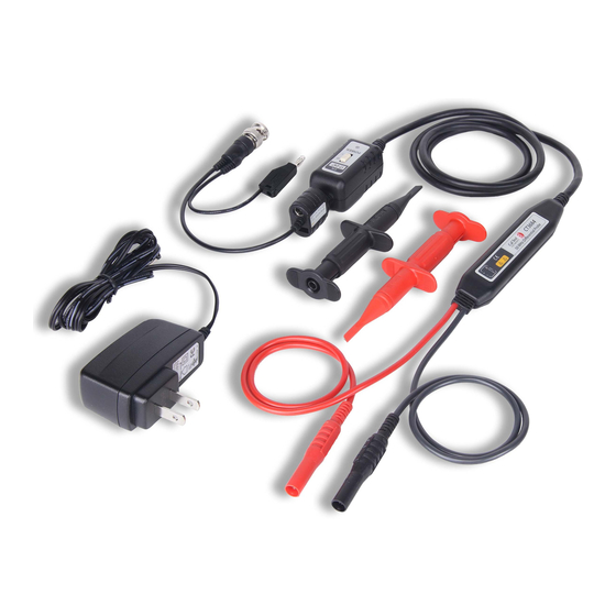
2.1 CT3684 & CT3685 Description Output BNC LED Power Indicator 9 VDC cable, 90 cm, Adapter with 4 mm Input Banana Plug Ground Lead Power On/Off Switch Probe Body Leads, 50 cm Hook Probes Figure 1 Front Panel Diagram CT3684 and CT3685 caltestelectronics.com 800-572-1028... -
Page 7: Using The Probe
3 Using the Probe 3.1 Power Connection Connect the 9 VDC adapter to the input on the probe. See Figure 1. Plug the adapter to power. WARNING At the time of powerig on the probe, the input leads must not be connected to an item to be tested. -
Page 8: Inspection Procedure
Set the oscilloscope input to DC coupling and 1V/div. Center the trace on the display. Set the attenuation setting on the oscilloscope to match the probe 10x (CT3684) and 100x (CT3685). Connect the hook probes to the leads. Connect the black hook probe to the ground connection on the oscilloscope and the red hook probe to the test signal on the oscilloscope (1 kHz for example). - Page 9 1 MΩ impedance input. When the oscilloscope is set to 50 Ω input, the actual vertical scale will be doubled: 10 V/div for the 10x probe (CT3684) and 100 V/div for the 100x probe (CT3685). See Table Vertical Scale on Oscilloscope...
-
Page 10: Electrical Specifications
Specifications All specifications apply to the unit after a temperature stabilization time of 20 minutes over an ambient temperature range of 25 °C ± 5 °C. Electrical Specifications CT3684 CT3685 Bandwidth (-3dB) 50 MHz (driving 1 MΩ oscilloscope input) Rise Time (10%-90%) -
Page 11: Environmental Characteristics
5 Voltage Derating Curve The derating curve of the absolute maximum input voltage in common mode is show as follows: CT3684 & CT3685 Maximum Input Voltage Derating Curve 1000 Frequency (Hz) Figure 3 Derating Curve caltestelectronics.com... -
Page 12: Service And Warranty Information
Units returned to Cal Test Electronics that have been subject to abuse, misuse, damage or accident, or have been connected, installed or adjusted contrary to the instructions furnished by Cal Test Electronics, or that have been repaired by unauthorized persons, will not be covered by this warranty. - Page 13 caltestelectronics.com 800-572-1028...
- Page 14 caltestelectronics.com 800-572-1028...
- Page 15 caltestelectronics.com 800-572-1028...
- Page 16 Part # 450844-001 20161222 © 2016 Cal Test Electronics...
Need help?
Do you have a question about the CT3684 and is the answer not in the manual?
Questions and answers