
Related Manuals for Stevens Aero Model Built It! Daddy-O 525


Summary of Contents for Stevens Aero Model Built It! Daddy-O 525
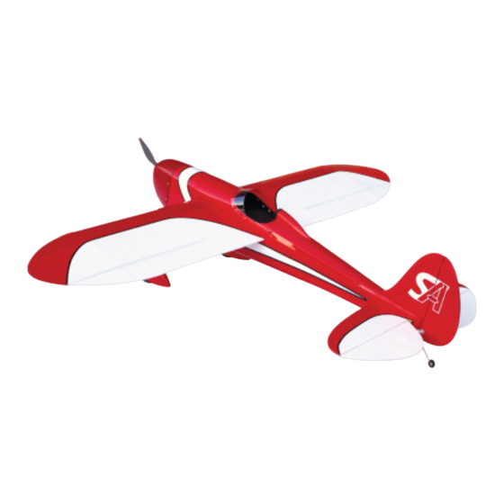
- Page 1 Daddy-O 525 Wing Span: 52.5 inches | Wing Area: 485 square inches | Average Flying Weight: 36 ounces Build Instructions - Version 1.24 (revised 06.08.2015)
- Page 2 Build Instructions WARRANTY Stevens AeroModel guarantees this kit to be free from defects in both material and workmanship at the date of purchase. This warranty does not cover any component parts damaged by use or modification. In no case shall Stevens AeroModel’s liability exceed the original cost of the purchased kit. Further, Stevens AeroModel reserves the right to change or modify this warranty without notice.
-
Page 3: Kit Contents
Build Instructions Project Checklist Kit Contents ☐ Laser cut wood (29 Sheets - See inventory on following pages) ☐ Illustrated Build Instructions (No plan sheet is required or included with kit) ☐ 1 - Wind screen, laser-cut PTEG ☐ 2 - Wire landing gear, pre-bent ☐... - Page 4 Build Instructions Project Checklist Continued Required Electronics (Available at StevensAero.com) ☐ 4-6 Channel transmitter and mini receiver. ☐ 3 - Hitec HS-65HB servos (Ailerons and Elevator) ☐ 1 - Hitec HS-65MG servo (Rudder) ☐ 2 - 12 in. servo extensions (Ailerons) ☐...
- Page 5 Build Instructions General Assembly Instructions Thank you, for purchasing this Stevens AeroModel Daddy-O 525™. A design inspired by Thayer Syme’s RC version of the McGuire Daddy-O free flight embryo model. This kit has been developed and manufactured using state of the art CAD/CAM systems and features a unique interlocking construction process that, when compared to traditional methods found in other model aircraft kits, save countless hours of measuring, cutting, sanding, and fitting.
- Page 6 Build Instructions Laser Cut Parts Inventory SAK-D525 01/29 SAK-D525 02/29 SAK-D525 03/29 SAK-D525 04/29 SAK-D525 05/29 SAK-D525 06/29 Daddy-O 525 - Build Instructions © 2010 Stevens AeroModel, all rights reserved.! Page 6...
- Page 7 Build Instructions Laser Cut Parts Inventory SAK-D525 07/29 SAK-D525 08/29 SAK-D525 09/29 SAK-D525 10/29 SAK-D525 11/29 SAK-D525 12/29 Daddy-O 525 - Build Instructions © 2010 Stevens AeroModel, all rights reserved.! Page 7...
- Page 8 Build Instructions Laser Cut Parts Inventory SAK-D525 13/29 SAK-D525 14/29 SAK-D525 15/29 SAK-D525 16/29 SAK-D525 17/29 SAK-D525 19/29 SAK-D525 20/29 Daddy-O 525 - Build Instructions © 2010 Stevens AeroModel, all rights reserved.! Page 8...
- Page 9 Build Instructions Laser Cut Parts Inventory SAK-D525 21/29 SAK-D525 22/29 SAK-D525 23/29 SAK-D525 24/29 SAK-D525 25/29 SAK-D525 26/29 Daddy-O 525 - Build Instructions © 2010 Stevens AeroModel, all rights reserved.! Page 9...
- Page 10 Build Instructions Laser Cut Parts Inventory SAK-D525 27/29 SAK-D525 28/29 SAK-D525 29/29 Daddy-O 525 - Build Instructions © 2010 Stevens AeroModel, all rights reserved.! Page 10...
-
Page 11: Fuselage Construction
Build Instructions Fuselage Construction ☐ Cut three 1-1/32 in. lengths from the provided ☐ Install F000 wing saddles to pre-cut holes in 6 in. length of 3/16 in. dia. aluminum tubing. F0 as illustrated. Tack glue F000 only at tab and notch joints. - Page 12 Build Instructions Fuselage Construction Cont. ☐ Install F00 through former F0 as illustrated. ☐ ☐ Test fit LG3 within fuselage on top of LG2 Tack glue at tab and notch locations. interlocking part with F2 and LG1. Note LG3 is designated “a” or “b” match “a/b” designation to “a/b”...
- Page 13 Build Instructions Fuselage Construction Cont. ☐ Use a 1/8 in. dia. drill bit to clean up landing ☐ Fit balsa former F3a to fuselage assembly as gear leg pocket created by LG1, LG2, LG3, illustrated. Pay close attention to FRONT/ and LG4.
- Page 14 Build Instructions Fuselage Construction Cont. ☐ Fit one fuselage side and former F1 firewall to ☐ Tack glue LG7 forward of F3a where the parts fuselage assembly. (F1 must be installed tab and notch together. Align and bond with so that flanged side of blind nuts faces thick CA, LG8 within fuselage side to capture inside fuselage towards former F2.) Match LG7.
- Page 15 Build Instructions Fuselage Construction Cont. ☐ Fit LG9 on top of LG7 and run forward within ☐ Gently work parts F8 and F1a to fit at bottom notch of previously installed LG8. Install of fuselage assembly between formers F1 opposite side LG8 at this time as well. Test fit and F2.
- Page 16 Build Instructions Fuselage Construction Cont. ☐ Fit former F7 between fuselage sides at tail ☐ Install F10 (with arrow facing forward) end of fuselage assembly. Tab in F7 will fit in spanning formers F3a, F4a, F5a, F6a, and notch of former F11. “U”...
- Page 17 Build Instructions Fuselage Construction Cont. ☐ With parts F14 moistened, gently wrap to Bond last 8 in. length of 3/32 in. x 3/16 in. balsa strip wood through notch in F3a and meet at the fuselage centerline and retain nesting in pocket created at F00, F000, and with masking tape.
- Page 18 Build Instructions Fuselage Construction Cont. Next, use a sharp knife to remove inside plug Bond strip wood stringer spanning formers immediately to right and left side of F10 at F3a-F6a and finishing where stringer just former F6a. makes contact with fuselage side and previously installed stringer.
- Page 19 Build Instructions Fuselage Construction Cont. ☐ While strip wood installed in previous Fit former F13 to right and left side of F12. assembly step is allowed to dry, continue to Tabs in former fit to notches in F6b and F11 install rear turtle deck.
- Page 20 Build Instructions Fuselage Construction Cont. ☐ Once stringer work, in nose of model, has Repeat above process to bond right and left inside/outside stringers within turtle deck dried: Remove rubber bands, seat and bond formers. Inside stringer will finish flush with stringers to formers, then cut and sand back side of former F6b.
- Page 21 Build Instructions Fuselage Construction Cont. Battery Hatch ☐ Bond H1a to H1b to create part H1. If formers F3a - F6a have been properly installed (etching forward) tubing runs are clearly identified. View: Bottom View: Top ☐ Bond, two each, parts H2 to H1 as illustrated below.
- Page 22 Build Instructions Battery Hatch Cont. ☐ Fit hatch former H8 to assembly spanning H3- ☐ From three 24 in. lengths of 3/32 x 3/16 in. H7. Etched arrow on H8 should face toward strip wood stock, cut six 12 in. long stringers. front H3.
- Page 23 Build Instructions Battery Hatch Cont. Cockpit ☐ Bond 1/16 in. thick x 3/16 in. diameter rare ☐ Using medium CA glue, bond H10a and H10b earth (neo) magnet flush within pocket together over a flat work surface to create created by hatch parts H8 and H9. Bond first part H10.
- Page 24 Build Instructions Cockpit Cont. ☐ Fit three parts H16 to cockpit assembly ☐ Over a flat work surface, use medium CA to spanning formers H12a and H11. Arrow bond parts H17a and H17b creating part H17 etched on part H16 faces toward H11. With (cockpit sheeting).
- Page 25 Build Instructions Cockpit Cont. ☐ While hatch assembly dries, build spring Disassemble ball point pen and retrieve loaded latch assembly for cockpit. spring for use in latch assembly. From provided 12 in. length, of 1/16 in. dia. wire. Make a 90 degree bend 1/2 in. from end of wire.
- Page 26 Build Instructions Cockpit Cont. ☐ Insert provided 1/8 in. O.D. splined nylon ☐ Ply part H12c on latch assembly locates tubing into hole in H11. Tubing should finish within bottom center hole of H12b (hole is flush with outside edge of H11. Bond from keyed).
- Page 27 Build Instructions Cockpit Cont. Catches ☐ With latch properly installed bond the 1/64 in. ☐ The battery hatch is retained within the plywood doubler C3 on top of slot in H10 just fuselage by magnetic catches. The cockpit aft of H12b. Bend in wire latch nests within will be retained with a combination of slot to hold catch open fit length if required.
- Page 28 Build Instructions Catches Cont. Fit the Cockpit and Hatch ☐ With catches properly assembled and magnet ☐ Fit Cockpit assembly to fuselage between F2 polarity verified. Fit and bond Battery Hatch and F3a. Using a sanding block with fine grit catch C1 (tall) within fuselage matching tabs paper lightly sand cockpit to fit and flow with in catch to notches at F2.
-
Page 29: Vertical Stabilizer
Build Instructions Vertical Stabilizer ☐ Assemble outer frame work of Vertical Fin ☐ Reference first two bends flat to your work from parts V1, V2, and V3. Fill in center of fin table then make final bend 2-1/2 in. from 45 with V4 and truss parts marked “A”. -
Page 30: Horizontal Stabilizer
Build Instructions Vertical Stabilizer Cont. ☐ Fit Tail Gear wire within “L” pocket. Wire must ☐ Complete Vertical Stabilizer by sanding fit flush to surface of Rudder. Scrape pocket leading edge of Vertical Fin round. Sand a bit more if depth of pocket must be square, trailing edge of both Fin and Rudder. - Page 31 Build Instructions Horizontal Stabilizer Cont. ☐ Finish the Horizontal Stabilizer and Elevator Attention! Right and left Elevator halves are not to be joined into one assembly until final using a sanding block loaded with 400 grit assembly of model. paper, sand both top and bottom surfaces of Horizontal Fin and Elevator.
-
Page 32: Wing Construction
Build Instructions Wing Construction ☐ Lay parts R1 on table, mirrored to each other, ☐ Place WM1a on a solid work surface with with etching facing up. Place R1a on top of etched “TOP” side up. Drive two 8-32 blind R1, etched side up, matching the “TOP”... - Page 33 Build Instructions Wing Construction Cont. ☐ With R1 upright on work surface, key parts ☐ Fit and bond balsa part TE2a to underside of WM1 and WM2a to right and left R1 rib wing assembly beneath WM2a and between assemblies. Ensure etched “TOP”...
- Page 34 Build Instructions Wing Construction Cont. ☐ Use a razor plane and/or a sanding block to ☐ Use a straight edge to align T1a and T1b shape TE2a to match bottom profile of ribs R1 along scarf joint. Bond parts with medium at trailing edge of wing.
- Page 35 Build Instructions Wing Construction Cont. ☐ Fit tab in TE4 to notch in “squared” end of ☐ Tab rib R5 into T1 and TE5 and tack with TE5. Now fit TE4 and TE5 to notches in rib medium CA glue. Now, fit S1b to S1a Seat parts completely flush against rib spanning R4 and R5 and tack glue at ribs.
- Page 36 Build Instructions Wing Construction Cont. ☐ Fit tabs in leading edge of wing tip part WT to ☐ Fit top spar jig S2 to wing assembly, notch in R7. Gently work rib R8 into wing interlocking triangular tab/notches with lower assembly, interlocking with wing tip and S1b.
- Page 37 Build Instructions Wing Construction Cont. ☐ Fit 12 in. length of carbon flat stock spanning ☐ Repeat process (detailed in first instruction on recess in left and right ribs R1 and R2 and on this page) to fit 10 in. length of carbon flat top of S2 spar jig.
- Page 38 Build Instructions Wing Construction Cont. ☐ Fit and bond SW2 shear webs, between right ☐ From the 1/8 x 1/4 in. balsa stock, cut two 12 and left ribs R2 through R7, forward of spar in. lengths. Sand one end to fit snug against jig, captured by top and bottom spar caps.
- Page 39 Build Instructions Wing Construction Cont. ☐ Center 48 in. length of 1/4 in. square balsa ☐ Dry fit one 36 in. length of 1/8 x 3/16 in. balsa stock to “V” notch in leading edge of wing ribs stock to underside of wing. Join with strip R1 through R7.
- Page 40 Build Instructions Wing Construction Cont. ☐ Check fit of strip stock (turbulators) installed ☐ Cut two 12 in. lengths from remaining 1/8 x on prior assembly page. Turbulators should 1/4 in. balsa strip wood. Soak 12 in. strips fit flush with inner rib R1 but stand 1/16 in. with glass cleaner, tape into position shown at proud of remaining outer ribs R2-R7.
- Page 41 Build Instructions Fuselage Construction ☐ Bond balsa servo pocket trim SR1b on top of ☐ Once more hold the wing assembly flat on SR1a servo pocket frame at rib R5. your work table, top side up. Revisit/glue the following assembly parts with medium CA glue to ensure a thorough bond.
- Page 42 Build Instructions Aileron Construction ☐ Bond A2a and A2b together to create aileron ☐ Aileron control horn pocket. Create a A2 trailing edge. Make two aileron trailing sandwich of parts A5, A5a (ply), and A5. edges from parts. Match edges of parts and bond on top of each other in the order given above.
- Page 43 Build Instructions Aileron Construction, Cont. ☐ Fit parts A1a and A1b together perpendicular ☐ Fit and bond 11-3/4 in. length of carbon flat to each other along tab and notch joint to stock to both right and left aileron assembly in form A1 aileron leading edge.
- Page 44 Build Instructions Finishing / Final Assembly ☐ With the major framing completed cover the ☐ Measure 2-7/8 in. from trailing edge of cockpit following assemblies using AeroLITE or and make a mark 1/4 in. below top edge of AeroFILM available from StevensAero.com. cockpit.
- Page 45 Build Instructions Final Assembly Cont. Mount Rudder and Elevator Servos ☐ Use HS-65HB servo for elevator and Headrest HS-65MG (preferred) for rudder. Prepare servos for mounting by removing stock servo ☐ Use two 1/8 in. dia. drill bits to align the horn then using your radio to electronically following parts in order: HR3, HR2, HR1,...
- Page 46 Build Instructions Final Assembly Cont. ☐ Fit and bond ply part WP1 to receiving pocket Wheel Pants within each wheel pant assembly using thick CA glue. Wheel pant parts are identified by either an alpha or numeric designator. Numeric part numbers are “circled”...
- Page 47 Build Instructions Final Assembly Cont. ☐ Wheel bushings. Cut two 3/4 in. lengths from Wheel Pants, Cont. the provided 2 in. length of 5/16 in. dia. aluminum tubing. Next, use a razor plane to clean up taper and begin rounding over top of wheel pant. 3/4 in.
- Page 48 Build Instructions Final Assembly, Cont. Wheel Pants, Cont. ☐ Gather 2-1/2 in. dia. wheels (with bearing ☐ Repeat assembly for opposite gear leg. installed), landing gear legs, ply part WP2, and eight (four per side) #2 x 1/4 in. sheet metal screws.
- Page 49 Build Instructions ☐ Test fit gear fairing over landing gear leg. Final Assembly Cont. Fairing sits on top of gear leg wire with straight edge of fairing facing forward. Use a Gear Leg Fairings sanding block to match top and bottom edges of fairing to fuselage side and wheel pant.
-
Page 50: Motor Mount
Build Instructions Final Assembly Cont. Motor Mount ☐ Test fit, then using thick CA, bond M3b with FRONT side facing up as illustrated. When ☐ Face motor mount part M3a etched side down bonding M3b keep glue well clear of blind nut on work table and drive four 4-40 blind nuts threads. -
Page 51: Battery Hold Down
Build Instructions Final Assembly Cont. ☐ Connect ESC to motor and fish wires through ☐ Fit cowl over fuselage (center motor shaft back of motor mount and into fuselage. hole in cowl to output shaft of motor) and temporarily retain with masking tape. Drive four #2 x 1/4 in. - Page 52 Build Instructions Final Assembly Cont. ☐ Using medium CA, bond hinges within Flying Surfaces Rudder and Vertical Fin leaving a 1/64 in. gap between parts at hinge line. Optional: Seal ☐ Cut CA hinge material into three pieces of along hinge line with covering material. equal width across short length of full size hinge stock.
- Page 53 Build Instructions Final Assembly Cont. ☐ Use a sharp knife to remove covering over Flying Surfaces vertical fin pocket on top and back of fuselage. Mount vertical fin within pocket and ☐ Use a sharp knife to remove covering over secure with Medium CA glue.
- Page 54 Build Instructions Final Assembly Cont. ☐ With cockpit removed from fuselage. Mount Flying Surfaces wing centered over wing saddle. Pass three wing mounting bolts through center crutch. ☐ Use methods described previously to hinge and secure right and left aileron to wing Two bolts installed at right and left of fuselage assembly (use a minimum of three CA hinges near wing leading edge...
-
Page 55: Control Linkage
Build Instructions Final Assembly Cont. Flying Surfaces Cont. ☐ Make two aileron push rods. Cut a 3-7/8 in length of 0.045 in. dia. wire, then make a 1/4 ☐ With Horizontal Stabilizer square within in. 90 deg. bend to one end. fuselage, bond top and bottom of Stabilizer on both right and left sides of model. -
Page 56: Final Assembly
Build Instructions Final Assembly ☐ Center both Rudder and Elevator to align with Control Linkage Cont. centerline of Vertical and Horizontal Fin. ☐ Install Du-Bro 1/2A control horn [DUB107] to left side of Rudder and make pushrod connection, to third hole from inside of horn, using Micro2 E/Z link provided with pushrod kit [DUB922] to secure. - Page 57 Build Instructions Flight Control Setup and Balance Pre Flight to First Flight ☐ First, mechanically and electronically center Have an experienced pilot assist you with pre- all control surfaces and servos; zero any trim flighting your new model. Just like having settings in radio.
- Page 58 Build Instructions Pre-Flight Cont. Feedback Welcome ☐ Clear Prop! - Before applying power to the Have your say. Please share your completed model, clear and keep clear of the prop arc. model photos, thoughts, and experiences with As electric motors are capable of inflicting our staff.
Need help?
Do you have a question about the Built It! Daddy-O 525 and is the answer not in the manual?
Questions and answers