Table of Contents
Advertisement
Quick Links
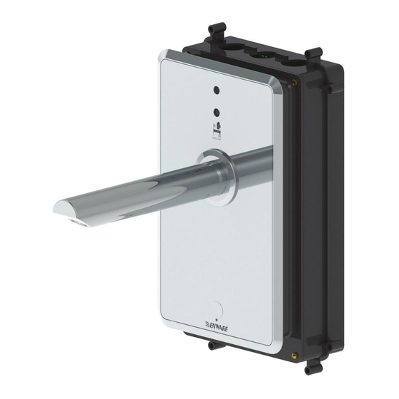
Enware Touch Free Sensor Tap
ENM620/ENM621
Installation, Operating & Maintenance Instructions
AUTO SENSE SYSTEM
ON DEMAND SENSOR SYSTEM
I00271_Jan 21
Call 1300 369 273
www.enware.com.au
Enware Australia Pty Limited
9 Endeavour Rd Caringbah NSW 2229 Australia
Ph: +61 2 8556 4000 info
enware.com.au
@
The Bluetooth® trademark and logos are property of Bluetooth SIG, Inc., and their usage is licensed for Orasgroup.
Advertisement
Table of Contents

Related Manuals for enware ENM620

Summary of Contents for enware ENM620
- Page 1 Enware Touch Free Sensor Tap ENM620/ENM621 Installation, Operating & Maintenance Instructions AUTO SENSE SYSTEM ON DEMAND SENSOR SYSTEM The Bluetooth® trademark and logos are property of Bluetooth SIG, Inc., and their usage is licensed for Orasgroup. I00271_Jan 21 Call 1300 369 273 www.enware.com.au...
-
Page 2: Product Components Front Of Wall
230mm Fixed Spout with Laminar Flow - Mains Powered ENMAM C2L3 - 8Lpm ENMAM C2L5 - 6Lpm MAINS ENMAM C2L6 - 4.5Lpm Also available with 200mm spout: ENMAM C1L3 - 8 Lpm MAINS ENMAM C1L5 - 6 Lpm ENMAM C1L6 - 4.5 Lpm Call 1300 369 273 www.enware.com.au... -
Page 3: Product Components In-Wall
PRODUCT COMPONENTS IN WALL BATT BATTERY OPERATED ENM620 6V Battery Operated In-Wall Component BATT NOTE WHEN PLACING AN ORDER IN WALL Battery operated Mains operated (back of wall) IN WALL IN WALL component (back of wall) (back of wall) is ordered... -
Page 4: Table Of Contents
Enware Touch Free Sensor Tap ENM620/ENM621 CONTENTS PRODUCT COMPONENTS FRONT OF WALL PAGE 2 PRODUCT COMPONENTS IN-WALL PAGE 3 TECHNICAL INFORMATION PAGE 5 INSTALLATION COMPLIANCE PAGE 7 INSTALLATION PROCEDURE - IN-WALL PAGE 8 INSTALLATION PROCEDURE - FRONT OF WALL PAGE 11... - Page 5 ON DEMAND SENSOR IN WALL COMPONENTS 32.5 (FLANGE DIMENSION) 6 THRU TYP 1/2" (BSP) INLET 1/2" (BSP) OUTLET 73.2 73.2 66.2 15 mm IN WALL ADJUSTMENT TRIM DOWN BOX COVER 79.5 TO SIZE AFTER INSTALLATION www.enware.com.au Call 1300 369 273...
-
Page 6: Technical Information
Adjustable * In accordance with AS/NZS3500. Enware products are to be installed in accordance with the Plumbing Code of Australia (PCA) and AS/NZS3500. Installations not complying with PCA and AS/NZS3500 may void the product and performance warranty provisions. -
Page 7: Installation Compliance
WARNING: Do not cut the electrical cable of the sensor tap, or alter the product in any way to suit installation. Damage caused in this way will void warranty. Transformer with 4.5m Extended Cable (ENMS230) are available if extra power cable length is required www.enware.com.au Call 1300 369 273... -
Page 8: Installation Procedure In Wall
SET-OUT HEIGHTS Suggested heights from finished floor: Spout 1050mm outlet 1120mm to point of water discharge (Australasian Health Facility Guidelines) Top of 850mm basin 865mm (Australasian Health Facility Guidelines) 800 - 830mm (Reference: AS1428.1- 2009) Call 1300 369 273 www.enware.com.au... - Page 9 STEP 2 If installing within a frame wall, fit mounting timber in the desired location for Box support. Enware recommends 13mm ply wood fixed between two vertical in-wall studs. Important: The depth of Box from finished wall to the back of the Box must be between 80mm - 95mm.
- Page 10 Box to connect to the sensor. If the cable is not long enough, use an extended transformer (4.5m - ENMS230 - available from Enware). Use a conduit to run the transformer cable between the power point and the box, to allow for easy component replacement in future.
-
Page 11: Installation Procedure Front Of Wall
Box. STEP 2 Fit spout support nut onto 1/2" BSP outlet thread. STEP 3 Fit the chrome back support bracket and secure with four screws supplied. CHROME BACK SUPPORT BRACKET CHROME FACE PLATE www.enware.com.au Call 1300 369 273... - Page 12 3/8” Allen key, making sure it finishes hard up against the spout support nut. STEP 7 Connect the sensor cable to the solenoid first. Make sure the lines on the two connectors align. Call 1300 369 273 www.enware.com.au...
- Page 13 2x lower tabs into the 2x voids in the base of the face plate bracket until it sits flush. Secure in place using the 2x M4 Allen head screws and tighten with an Allen key. www.enware.com.au Call 1300 369 273...
- Page 14 Ensure the grub screw fits into the groove of the spout retainer, and is fitted all the way into the spout. STEP 14 Restore water supply to the ta and test the tap operation. Call 1300 369 273 www.enware.com.au...
-
Page 15: Operating Instructions
Afterflow time, sensor range, and sensor sensitivity can be adjusted, and Auto Flush function can be activated. See Sensor Program on page 24. *After installation this sheet may be affixed adjacent to the tap for user instruction. www.enware.com.au Call 1300 369 273... - Page 16 Place hand in front of sensor at Move hand in towards sensor and 10cm for 1 sec pulling up Wave quickly in front of sensor Hand too close to sensor (does not activate) (does not activate) Call 1300 369 273 www.enware.com.au...
-
Page 17: Thermal Disinfection Procedure
6. Once decontamination procedure has completed and the water supply to the sensor tap is turned off, connect sensor to solenoid. 7. Fit front plate and spout back on. 8. Restore water supply to the sensor tap. www.enware.com.au Call 1300 369 273... -
Page 18: Service And Maintenance
SERVICE AND MAINTENANCE The ENWARE Touch Free Sensor Tap will only require minimal preventative maintenance work to ensure it operates at its optimum level of performance. Every few years or as required, spout aerator and strainer check valve assembly should be checked for debris, and cleaned if required. - Page 19 SERVICE AND MAINTENANCE SERVICING THE STRAINERS AND CHECK VALVES Enware Product Code: ATMS693 - Strainer / Check Valve Assembly (1 Pair) Periodically the combined non-return and strainer assemblies need to be checked for cleanliness. Prior to servicing, ensure the isolation valve is closed, or the water supply to the tap is turned off.
- Page 20 Check internal sealing membrane for debris or damage, O-RING by taking off the lower cap. If damaged, replace with a new solenoid membrane (Enware Part - ENMS212). The membrane and lower cap should be cleaned, checked for physical damage and then thoroughly rinsed with clean water.
- Page 21 Remove the battery from within the box, and disconnect it from sensor cable. STEP 3. Open the casing cover and change the battery. Use only 6V Lithium 2CR5 battery (Enware Part ENMS204). Fit the battery casing cap back on. STEP 4.
- Page 22 Pete’s Plug to take measurements. CLEANING Enware products should be cleaned with a soft damp cloth using only mild liquid detergent or soap and water. Do not use cleaning agents containing a corrosive acid, scouring agent or solvent chemicals. Do not use cream cleaners, as they are abrasive.
- Page 23 Aerator - 4.5 lpm laminar flow 673417 Spout grub screw - M5 Dog point 672453 Face plaste fixing screw (each) 671484 (socket HD cap SS304 M4 x 10 CSK) Pete's Plug 1/4" Test Point Adaptor ATMS1221 www.enware.com.au Call 1300 369 273...
-
Page 24: Sensor Program
Apple, the Apple logo, iPhone, iPad, and iPod touch are trademarks of Apple Inc., registered in the U.S. and other countries. App Store is a service mark of Apple Inc. Google Play and the Google Play logo are trademarks of Google Inc. Call 1300 369 273 www.enware.com.au... - Page 25 4. Activate the sensor tap several times for the new settings to come into effect. For explanation on the program settings listed, see the explanation page (press the button on the App), or refer to next page. www.enware.com.au Call 1300 369 273...
- Page 26 Enter the name of your choice to identify the location of the tap. Password: Set the password of your choice to limit access to the settings by others (e.g. for public places). Default password for factory setting is "Electra". Call 1300 369 273 www.enware.com.au...
-
Page 27: Troubleshooting
(refer to sensor program on page 24.) Sensor green light Sensor is in Cleaning Mode Sensor is in Cleaning Mode. See Sensor Program blinks on page 24 for more details. www.enware.com.au Call 1300 369 273... -
Page 28: Product Warranty
All notifications and accompanying forms must be sent to us marked for the attention of the Enware Australia Pty Except as provided or referred to in this document, we Limited, 9 Endeavour Road, Caringbah NSW 2229. We...
Need help?
Do you have a question about the ENM620 and is the answer not in the manual?
Questions and answers