Advertisement
Quick Links
Connection Examples
Connection to Star-delta Motors
Connection Combined with a Frequency
Converter and a Delta-wye Circuit
BTR NETCOM GmbH
Phone +49 7702 533-0
Im Tal 2
Fax
+49 7702 533-433
78176 Blumberg - Deutschland
www.btr-netcom.com
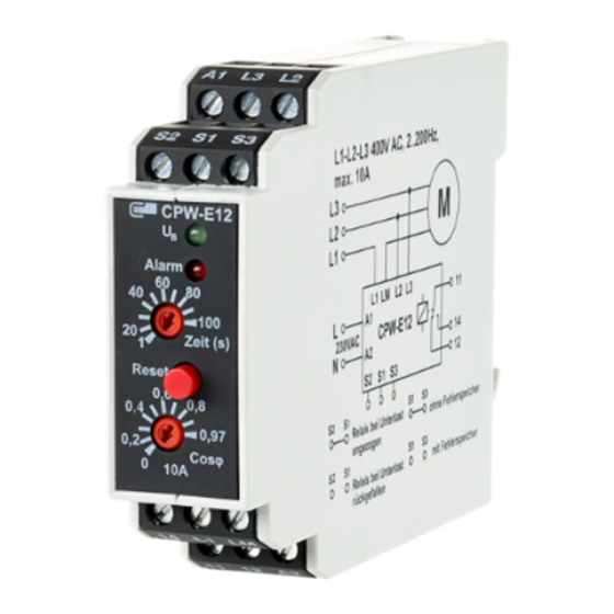
CPW-E12
Motor Monitoring Relay
1102810520
110281052013
Technical Data
Input
nominal voltage
power consumption (max)
operating voltage range
frequency range
duty cycle
input voltage (motor)
input current
(load current)
load inrush current
setting range cosj
response time
operating temperature range
storage temperature range
Output
output contact
contact material
switching voltage (max.)
making/breaking capacity
continuous current
contact fuse
permissible switching frequency
isolation per VDE 0110
rated voltage
overvoltage category
pollution degree
test voltage (coil/contact)
EMC test
Housing
type of protection (EN 60529)
wire cross section
mounting position
colour
weight
housing dimensions WxHxL
modular
122006/1/02/PDF/899 100-01
230 V AC - 1 ... 10 A
230 V AC - 0.2 ... 2.5 A
Functional Description
Wiring Diagram
The cosϕ monitor is used to detect an
underload. Adjustable response value
and response time. It can also be used
together with a frequency converter
(frequency 2 to 200 Hz). Monitoring is
accomplished by recognising the phase
shift between current and voltage. This
phase angle varies according to the load
of the motor. The instrument is
equipped with a green LED for operating
voltage indication and a red LED for
error indication.
Declaration of Conformity
The device meets the requirements of the CE guidelines.
Conformity was proved. The declaration of conformity is available
230 V AC
at the manufacturer BTR NETCOM GmbH.
1.5 VA
0.9 - 1.1 x U
N
Notes Regarding Device Description
2 ... 200 Hz
100 %
These instructions include indications for use and mounting of the
230 V AC / 400 V AC
device. In case of questions that cannot be answered with these
min. 0.2 A, max. 10 A
instructions please consult supplier or manufacturer.
The indicated installation directions or rules are applicable to the
100 A (<0.5 s)
Federal Republic of Germany. If the device is used in other countries
0 .. 0.97 (relative scale)
it applies to the equipment installer or the user to meet the
1 .. 100 s
national directions.
0 °C ... +55 °C
Safety Instructions
-25 °C ... +70 °C
Keep the applicable directions for industrial safety and the
prevention of accidents as well as the VDE rules.
1 changeover contact
Technicians and/or installers are informed that they have to
AgNi
electrically discharge themselves as prescribed before installation or
250 V AC
maintenance of the devices.
1000 VA
Only qualified personnel shall do mounting and installation work
4 A
with the devices, see section "qualified personnel".
4 A
The information of these instructions have to be read and under-
1200 switching cycles/h
stood by every person using this device.
Symbols
250 V AC/DC
Warning of dangerous electrical voltage
III
2
Danger
2000 V, 50 Hz 1 min.
means that non-observance may cause risk of life,
emission per EN 50 081 T1
grievous bodily harm or heavy material damage.
interference immunity
per EN 50 082 T2
Qualified Personnel
Qualified personnel in the sense of these instructions are persons
housing IP50,
who are well versed in the use and installation of such devices and
terminal blocks IP20
whose professional qualification meets the requirements of their
2.5 mm²
work.
any
This includes for example:
green
Qualification to connect the device according to the VDE specifi-
170 g
cations and the local regulations and a qualification to put this
22.5 x 75 x 100 mm
device into operation, to power it down or to activate it by
without spacing
respecting the internal directions.
Knowledge of safety rules.
Knowledge about application and use of the device within the
equipment system etc.
Function Diagram
Advertisement

Related Manuals for Metz Connect BTR NETCOM CPW-E12

Summary of Contents for Metz Connect BTR NETCOM CPW-E12
- Page 1 CPW-E12 Connection Examples Motor Monitoring Relay Connection to Star-delta Motors 1102810520 230 V AC - 1 ... 10 A 110281052013 230 V AC - 0.2 ... 2.5 A Functional Description Wiring Diagram Function Diagram The cosϕ monitor is used to detect an underload.
- Page 2 Mounting Display and Operation Wiring Diagrams Connection Examples On standard DIN rail per DIN EN 50022 (35 x 7.5 mm), in junction Connection to Two-stage Motors with boxes and/or on distribution panels. green LED - operating voltage Separate Windings indication red LED - error indication rotary switch for time setting reset push button...
Need help?
Do you have a question about the BTR NETCOM CPW-E12 and is the answer not in the manual?
Questions and answers