Table of Contents
Advertisement
Advertisement
Table of Contents

Related Manuals for SainSmart Genmitsu PROVerXL 4030


Summary of Contents for SainSmart Genmitsu PROVerXL 4030
- Page 1 Genmitsu PROVerXL 4030 V1.0 Aug 2020 CNC Router...
- Page 2 Contents ............................Welcome ............................Disclaimer ..........................Specifications ........................... Part 1 - Unboxing ....................Part 2 - Mechanical installation ..........................Part 3 - Wiring ......................... Part 4 - Software Setup ........................Part 5 - Test Project ........................Part 6 - Z Probe Setup...
- Page 3 Welcome Thank you for purchasing the Genmitsu PROVerXL 4030 CNC Router from SainSmart. Included in your package will be a USB Stick, you will find: ● PDF version of this manual ● Windows USB Driver ● GrblControl/Candle software for Windows ●...
- Page 4 ● Always place the CNC Machine on a stable surface. ● The SainSmart Genmitsu CNC Machine is supplied with Switchable Power Supply 230 VAC or 115VAC. Never use a different power supply; it may cause malfunctions or damage to the machine.
- Page 5 Specifications Working Area 400 x 300 x 110mm Motor NEMA23 Input Voltage 115V/230V Input Current 8.5A/115V; 4A/230V Spindle Speed 12000r/min Spindle Power DC24V 300W Drive System Leadscrew T10 MDF Spoilboard Size 300 x 400 mm Firmware GRBL 1.1 Emergency Stop Switch Limit Switch X, Y, Z Speed Control Button...
- Page 6 Part 1 - Unboxing Please make sure all the following parts are included. If you are missing any part or have any questions, please email us at support@sainsmart.com Mechanical Parts List X-Axis & Spindle Y-Axis Base Assembly Spindle Collet Z-Axis Assembly...
- Page 7 (2) Drag Chain Mount Cable Management Drag Chain Mount Bakelite Sheet MDF Board MDF Spoil Board 175 x 100 x 5mm 175 x 100 x 5mm Electrical Parts List PROVerXL Power Cable (US) USB Cable A-B Control Center 1.2M...
- Page 8 Tools/Accessories Parts List (10) Engraving Bit Kit Probe (4) Material Clamp 30 Degree, 0.2mm Cutting area, Z-Height Mapping Probe 3.175 Diameter (10) Nano Blue Coat Bits (5) Allen Wrench Wrench 3.175mm Shank, Cutting Edge 2.0mm, 2.5mm, 3.0mm, Diameter: 0.8-3.0mm 4.0mm, 5.0mm Genmitsu CNC Router PROVerXL 4030 V1.0 Aug 2020...
- Page 9 Screws/Other Parts List (4) M5 x 8mm (14) M5 x 16mm (6) M5 x 20mm (2) M5 T- Nut Socket Cap Screw Socket Cap Screw Socket Cap Screw (8) M5 x 50mm (4) M5 x 55mm (2) M4 x 6mm (2) M4 x 8mm Socket Cap Screw Socket Cap Screw...
- Page 10 Optional Accessories (Not Included) Consider following optional upgrades or accessories to make your CNC experience better! You can find them on www.sainsmart.com. Save 10% with discount code PROVerXL Router Bits Holder CNC Router Bits Resin Board for CNC Acrylic Sheet for CNC,...
- Page 11 Part 2 - Mechanical installation 2.1 Preparing your Base Assembly What you will need (2) Stepper Y-Axis Base Assembly (2) Coupler Motor Mount (2) NEMA 23 (8) M5 x 50mm Allen Wrench Stepper Motor Socket Cap Screw...
- Page 12 Step 1: Inspect your Base Assembly after removing it from the Step 4: Next comes the Motor Mounts & Stepper Motor. packaging. Before starting assembly, verify the base is square Lay the Stepper Mount on your flat surface, positioning it by using a 90-degree straight edge, as shipping may have so the open side will not face down when installed.
- Page 13 2.2 Finishing your Base Assembly What you will need (4) M5 x 16mm (6) M5 x 20mm Y-Axis Base Assembly Socket Cap Screw Socket Cap Screw MDF Spoil board (2) Dust Baffle Allen Wrench Step 1: Position the MDF Spoilboard on the PROVerXL 4030 Step 2: Align each Dust Baffle to the side of the spoil Base and align with the screw holes at the front and back board, align with the screw holes and tighten down with...
- Page 15 2.3 Preparing your X-Axis Gantry What you will need X-Axis & Spindle Coupler Stepper Motor Mount Z-Axis Assembly (2) NEMA 23 (4) M5 x 55mm Allen Wrench Stepper Motor Socket Cap Screw...
- Page 16 Step 1: Install the flexible coupler to the X-Axis Leadscrew. Step 3: Mount the assembly to the X-Axis. Tighten the Be sure to loosen the grub screws to ensure the shaft full grub screws on the coupler. Manually twist the wheel seats inside.
- Page 17 2.4 Finishing your X-Axis Gantry What you will need X-Axis & Spindle (2) M5 x 8mm Drag Chain Mount Allen Wrench Z-Axis Assembly Socket Cap Screw Step 1: Position the X-Axis Limiter to the rear of the Spindle Carriage as shown in the diagram. Install the bracket and tighten the screws.
- Page 19 2.5 Finishing Frame Assembly What you will need (8) 5mm (8) 5mm (8) M5 x 16mm Allen Wrench Spring Washer Flat Washer Socket Cap Screw Step 1: Position the X-Axis gantry onto the Y-Axis carriage mounts Step 2: Secure the opposite side to complete the as shown in the diagram.
- Page 21 2.6 Installing the X-Axis Drag Chain What you will need Drag Chain Mount (2) T- Nut M5 Allen Wrench (2) M5 x 8mm (5) M4 x 6mm Cable Management Socket Cap Screw Socket Cap Screw Drag Chain Step 1: Per the diagram you will install the X-Axis drag chain Step 2: Position the Drag Chain as shown in the diagram.
- Page 23 2.7 Installing the Y-Axis Drag Chain What you will need (2) M5 x 16mm (2) 5mm (2) 5mm (2) M4 x 8mm Socket Cap Screw Spring Washer Flat Washer Socket Cap Screw (2) Drag Chain Mount Cable Management Allen Wrench Step 1: Position the narrow drag chain mount to the rear of Step 3: Position the drag chain per the diagram using the machine as shown in the diagram.
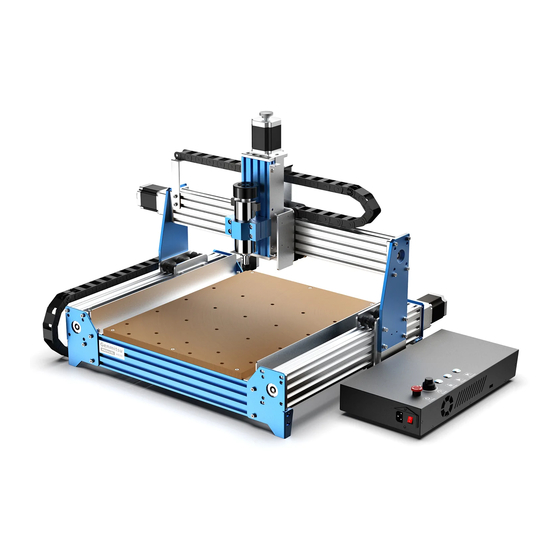
- Page 24 Congratulations! Now your PROVerXL machine body is fully assembled!
- Page 25 Part 3 - Wiring 3.1 Wiring Your Electronics Step 1: Start with the Spindle and X-Axis Carriage. Using the labeled cable ends you need to connect the Z-Axis Limit Switches to the Cable Step 2: Connect your Z-Axis Stepper Motor whip and wire the Spindle (there is no requirement for which color goes onto which side of the spindle).
- Page 26 Step 3: Connect your Limit Switches X-Axis Limit Switches Y-Axis Limit Switches Step 4: Wire the Y-Axis Stepper Motors. Find the longer Y-Axis Motor cable (Y2) and run that to the left side while reserving the shorter cable marked X for the X-Axis Motor and finally the medium length cable (Y1) for the right-side Y-Axis motor. Y2 to Left Motor and Y1 to Right Motor Cables to Control Box side X Axis...
- Page 27 Step 5: Follow the Wiring Diagram Below in order to connect all the wires from the Cable Whip (Looks like central image above). Voltage X-Axis Y-Axis Y-Axis (Y1) Z-Axis Switch Motor (Y2) Motor Motor Spindle Z-Probe Z-Limit Switch Y-Limit Switch X-Limit Switch Laser Module Power...
- Page 28 3.4 Label Description Mark Description Mark Description USB interface -LASER Laser module interface Power AC Power Input Speed Spindle RPM Speed Power ON Unlock Unlock Motors Power OFF Spindle + Positive Spindle - Negative Offline controller (Note: Only Offline controller connect to our offline controller) X Axis motor interface Emergency stop switch interface...
- Page 29 3.5 Final Checks The Axis leadscrews are lubricated at the factory; however, we recommend you inspect drive screws and reapply if needed. It is suggested you use a “Dry” PTFE based lubricant or similar product (not included) Lubricate to help prevent debris and dust from sticking to the rods or leadscrews. the Axes Please Note: Recommended normal maintenance includes cleaning of the threaded rods and lubricating as needed.
- Page 30 Part 4 - Software Setup Driver installation 1. Driver Installation Install the driver ( software Driver CH340SER.exe )
- Page 31 2. To Determine your Machine's COM port: • Windows XP: Right click on "My Computer", select "Manage", select "Device Manager". • Windows 7: Click "Start" Right click "Computer" Select "Manage" Select "Device Manager" from left pane. • In the tree, expand "Ports (COM & LPT)" •...
- Page 32 3. Grblcontrol (Candle) Connecting to the Controller First time use will require you setup the appropriate COM PORT and Baud rate. Step 1: Software should automatically select the port number. Step 2: If it does not recognize automatically select the “Baud” drop down menu and select 115200. Step 3: Click “OK”...
- Page 33 Part 5 - Test Project 1. Grblcontrol (Candle) 3D preview interface, hold the left mouse button, can rotate Angle, scroll the mouse wheel, Coordinate Display can be enlarged, or reduced. If you cannot see anything, you need to change to a computer Common operation button, with support for OpenGL2.0 the mouse icon on the above...
- Page 34 2. Run G code for processing 1. Click【open】 , Select the G code to run. 2. Click on the manual operation panel, move the spindle to the starting. point of the engraving, so that the tool and the workpiece just touch. 3.
- Page 35 Part 6 - Z Probe Setup Probe function introduction 1. Grblcontrol (Candle) Probe operating instructions Step 1: Probe commands editing Z14 is the height of the tool setting block, which requires actual measurement, and Z25 is the height of the tool lifting, which can be configured as required Probe G code After editing...
- Page 36 Step 2: Probe commands filled in Grblcontrol (Candle) Fill the Commands here...
- Page 37 Step 3: Connect the probe tool to the controller probe interface. Step 4: Click the "Z-probe" button, Z-axis automatic tool to zero. Click the "Z-probe" button...
- Page 38 Copyright © 2020 by SainSmart All rights reserved. This manual or any portion thereof may not be reproduced or used in any manner whatsoever without the written permission of the publisher, except for the use of brief quotations embodied in critical reviews...
- Page 39 Genmitsu Desktop CNC & Laser www.sainsmart.com support@sainsmart.com Vastmind LLC, 5892 Losee Rd Ste. 132, N. Las Vegas, NV 89081...
Need help?
Do you have a question about the Genmitsu PROVerXL 4030 and is the answer not in the manual?
Questions and answers
Purchased a new XL Genmitsu PROVer XL4030 and wtype and grade of Lubricant I need to lubricate the device. ant to know the
A "Dry" PTFE-based lubricant or a similar product is recommended for the SainSmart Genmitsu PROVerXL 4030.
This answer is automatically generated
I'm having problems with the controller going nuts. The log file for error reporting. What's the actual name of the file and how to report the problems I'm seeing?