Table of Contents
Advertisement
Advertisement
Table of Contents

Related Manuals for SainSmart GENMITSU 3018-PRO


Summary of Contents for SainSmart GENMITSU 3018-PRO
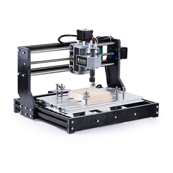
- Page 1 GENMITSU CNC ROUTER 3018-PRO USER MANUAL...
- Page 2 Contents Part 1: Package List --------------------------------------------------------------------------------------- 2 Part 2: Mechanical Installation ------------------------------------------------------------------------- 6 Part 3: Debugging ------------------------------------------------------------------------------------------ 19 Part 4: Offline Controller --------------------------------------------------------------------------------- 25...
- Page 3 Part 1: Package List Name Size Picture 20*40*290mm 20*20*360mm Aluminum Profile 300*180mm Guide Rail (X Axis) Ø10*360mm Guide Rail (Y Axis) Ø10*290mm T8(365mm) Lead Screw T8(295mm)
- Page 4 Name Size Picture Phenolic Resin Plate Stepmotor Spindle & ER11 X-Z Axis Assembly Slider Nut Seat Milling Cutter...
- Page 5 Name Size Picture 4P Motor Line Offline Controller Spindle Motor Line 24V Power Supply Control Board & Fan & Case USB Cable Plate Clamp...
- Page 6 Name Size Picture Winding Tube USB Stick 1.5mm,2.0mm,2.5mm, Allen Wrench 3.0mm,4.0mm M5*10 M5*16 Bolt M3*14 Copper Nut Nut 20M5 20*M5 Nut 30M5 30*M5 Spring Coupling & Set Screw...
- Page 7 Part 2: Mechanical Installation Bakelite:...
- Page 8 Step 1 Base Installation Bolt NAME SIZE QTY. Aluminum Profile 2040*290mm Phenolic Resin Plate Bakelite-A Prepare Phenolic Resin Plate Bakelite-B materials Bolt M5*16 M5*16 Slider Guide Rail (Y Axis) Ø10*290mm...
- Page 9 Step 2 Table Installation Bolt M5*16 x10Pcs NAME SIZE QTY. Aluminum Profile 300*180mm Copper Nut Spring Nut Seat Prepare Bolt M5*16 materials Bolt M3*14 Nut 30M5 30*M5 Lead Screw T8(295mm) Stepmotor Coupling & Set Screw...
- Page 10 Completed...
- Page 11 Step 3 Base & Bakelite-C Installation NAME SIZE QTY. Phenolic Resin Plate Bakelite-C Prepare materials Bolt M5*16 Nut 20M5 20*M5...
- Page 12 Completed...
- Page 13 Step 4 X-Z Axis Assembly Installation Bolt X-Z Axis Assembly NAME SIZE QTY. X-Z Axis Assembly Copper Nut Spring Prepare Aluminum Profile 20*20*360mm Copper Nut materials Guide Rail (X Axis) Ø10*360mm Lead Screw T8(365mm) Coupling & Set Screw Bolt M5*16 Bolt M3*14...
- Page 14 Step 5 Bakelite-D Installation NAME SIZE QTY. Phenolic Resin Plate Bakelite-D Prepare materials Bolt M5*16 M5*16 Nut 20M5 20*M5...
- Page 15 Completed...
- Page 16 Step 6 Spindle Installation...
- Page 17 Caution Tighten the bolt without using excessive force to prevent plastic damage.
- Page 18 Step 7 Control Board Installation Control board Bolt M5*10 x4pcs Nut 20*M5 x4pcs...
- Page 19 Step 8 Wiring Diagram Connect the red wire to the Stepmotor port next to the red mark Spindle Laser (12V 5Amax) (Not include) 24V DC Power adapter Connect your CNC to computer using the bundled USB cable POWER Offline controller ON/OFF...
- Page 20 Part 3: Debugging 1. Install the driver ( software Driver CH340SER.exe )
- Page 21 2. To Determine your Machine's COM port: • Windows XP: Right click on "My Computer", select "Manage", select "Device Manager". • Windows 7: Click "Start" Right click "Computer" Select "Manage" Select "Device Manager" from left pane. • In the tree, expand "Ports (COM & LPT)" •...
- Page 22 3. Open Grblcontrol software(software Grblcontrol GrblControl.exe) choose the correct port...
- Page 23 • Console window print ” [CTRL+X] < Grbl 1.1f ['$' for help]” If the connection is successful. • Console window print ” Serial port error 1: No such file or directory “ indicate that the connection is failed. successful unsuccessful...
- Page 24 • Grblcontrol Use The spindle speed: It does not represent the actual speed, and it represents the ratio. And this percentage is not linear. 100 = 100/1000 spindle 1000 = 1000/1000 100% max on/off 100% The X Y Z axis jog...
- Page 25 • Tool setting spindle should be on when moving the bits zero XY zero Z Use the jog to move the milling cutter. Then click button zeroXY and zeroZ. Open the G-code file Start working End...
- Page 26 Part 4: Offline Controller Notice: When using the offline controller, remove the USB cable from the PC. Offline controller and PC cannot be used together. 1. Connect offline controller to PC via USB cable.
- Page 27 2. Then copy the NC file to the offline controller.
- Page 28 3. Offline controller connected to the control board. 4. Press the [X+/X-/Y+/Y-/Z+/Z-] key to move the spindle to the machine origin, select the engraving file, click the [OK] key to start engraving.
- Page 29 5. Interface introduction A. Menu Page Ctrl Machine Control File Use the G-code file Press key [Y+] or [Y-] to select Press key [OK] to Enter...
- Page 30 B. Ctrl Page Reference direction X-axis positive direction X-axis negative direction Y-axis positive direction Y-axis negative direction Z-axis positive direction Z-axis negative direction OK/Spindle(SP) Spindle On/Off Long press to exit, short press to Exit/Step change step (0.1/1/5/10mm) Power to spindle (Press [OK]+[Z+]=add, SP:1% Press [OK]+[Z+]=reduce)
- Page 31 C. File Page Press key [Y+] or [Y-] to select file Press key [OK] to Enter Press key [OK] to begin if you are ready.
- Page 32 2711 Centerville Road, Wilmington, DE, 19808, United States...
Need help?
Do you have a question about the GENMITSU 3018-PRO and is the answer not in the manual?
Questions and answers