Table of Contents
Advertisement
Quick Links
Advertisement
Chapters
Table of Contents

Subscribe to Our Youtube Channel
Related Manuals for Martin Professional Extube


Summary of Contents for Martin Professional Extube
- Page 1 Extube user manual...
-
Page 2: Dimensions
The Martin logo, the Martin name and all other trademarks in this document pertaining to services or products by Martin Professional A/S or its affiliates and subsidiaries are trademarks owned or licensed by Martin Professional A/S or its affiliates or subsidiaries. -
Page 3: Safety Information
Warning! Do not look at exposed LEDs from a distance of less than 2.2 m (7 ft. 3 in.) from the front surface of the Extube without suitable protective eyewear. At less than this distance, the LED emission can cause eye injury or irritation. - Page 4 (earth-fault) protection. • Connect the fixture to AC power using an Extube input cap and the 13 A power cable supplied pre-installed on the input cap only. The power cable may not be changed by the user. If it is not suitable for your installation, contact Martin for assistance in selecting and installing an alternative power cable.
- Page 5 P R O T E C T I O N F R O M B U R N S A N D F I R E • Do not operate the fixture if the ambient temperature (Ta) exceeds 45° C (113° F). •...
- Page 6 Disposing of this product Martin™ products are supplied in compliance with Directive 2002/96/EC of the European Parliament and of the Council of the European Union on WEEE (Waste Electrical and Electronic Equipment), as amended by Directive 2003/108/EC, where applicable. Help preserve the environment! Ensure that this product is recycled at the end of its life.
-
Page 7: Table Of Contents
Contents Dimensions ......... . . 2 Safety Information . - Page 8 Notes Extube user manual...
-
Page 9: Introduction
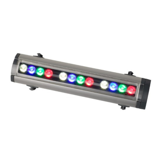
Introduction Thank you for selecting an Extube™, a compact LED-based color-changing lighting fixture from Martin™. The Extube is available in short 300 mm (11.8 inch) and long 1200 mm (47.2 inch) models. All models can be plugged into each other end-to-end to form an unbroken line of light. -
Page 10: Unpacking
• Two adjustable DIN rail mounting brackets • Two locking clips for interconnecting fixtures The following items are included with the Extube Power Connection Kit: • Input cap with 1.8 m (5 ft. 10 in.) power and data cable tails •... -
Page 11: Physical Installation
LEDs to be viewed from a distance of less than 2.2 m (7 ft. 3 in.). The Extube must be clamped onto a 35 mm DIN top-hat rail that is securely anchored to a suitable flat surface. Ensure that the supporting structure can bear the weight of all installed devices plus an adequate safety margin. -
Page 12: Mounting The Fixture
Mounting the fixture DIN rail The Extube is designed to be mounted on standard 35 mm top-hat DIN rail. Figure 1: Martin DIN rail dimensions Corrosion-resistant DIN rail can be ordered from Martin (see "Accessories"... -
Page 13: Mounting
Extube housing, slide the clamp a few millimeters to one side and retighten the screw. Note that you must install extra screws through the DIN rail into the mounting surface to secure Extube fixtures in vertical installations (see “Vertical mounting”... - Page 14 Extube and fasten each safety attachment to a separate anchoring point in the mounting surface itself, not the DIN rail.
- Page 15 To adjust the tilt angle: 1. See Figure 6. Insert a 4 mm Allen key in the holes next to the mounting clamp screws on the mounting brackets of all interconnected fixtures. Engage the Allen key in the screw inside each hole, apply a little inwards pressure and twist a quarter-turn clockwise to release the tilt lock.
- Page 16 See Figure 7. A small button on the opposite side of the mounting bracket to the tilt lock screw indicates whether the tilt lock is applied or not. Figure 7: Tilt lock indicator Extube user manual...
-
Page 17: Connections - General
Power in Figure 8: Connecting fixtures to data and power A second Extube can be plugged into the output end of this fixture, a third Extube can be plugged into the output end of the second fixture, and so on until the connected fixtures reach the maximum permitted length (see "Maximum interconnected length per power input"... - Page 18 Extension kits See Figure 10. It is possible to create a gap in a line of Extube fixtures (to pass a door, window or corner, for example) but keep the fixtures connected to each other by using an Extube Extension Kit that is available as an accessory.
- Page 19 (see "Accessories" on page 45 for details). Output and input caps must be secured with two locking clips each. Cable entry and drip loops Ensure that cables enter fixtures from below. See Figure 11. If necessary, form a drip loop in the cable just before it enters the fixture.
-
Page 20: Ac Power
AC mains power voltage and frequency The Extube accepts AC power at 100 - 120 and 200 - 240 V nominal, at 50 or 60 Hz. Do not connect the fixture to power at any other voltage or frequency. -
Page 21: Connecting To Power
Martin supplier for assistance. Connecting to power An Extube fixture or group of fixtures draws power via the 13 A power cable tail installed on an Extube power input cap. Details of standard US and EU conductor identification systems are given in Table 1. - Page 22 13 A minimum, following the plug manufacturer’s instructions. Table 1 shows some possible pin identification schemes; if pins are not clearly identified, or if you have any doubts about proper installation, consult a qualified electrician. Ensure that all connections are sufficiently protected from water. Extube user manual...
-
Page 23: Control Data Link
Control data link Extube fixtures must be connected via a data link to allow DMX control. The following considerations must be taken into account when planning the data link: • RS-485 data cable designed for exterior use is required for outdoor installations. - Page 24 (see "Maximum interconnected length per power input" on page 43), including lines of fixtures that are interconnected using Extube Extension Kits. Data connection pinouts XLR connection XLR connectors are suitable if the DMX controller has XLR output sockets.
-
Page 25: Connecting The Data Link
The Extube Connection Kit that must be ordered separately (EU type: P/N 91610086, US type: P/N 91610087) is supplied with a 1.8 meter (5 ft.10 in.) data cable tail for data connection. -
Page 26: Fixture Setup
Windows PC (a laptop is most convenient) and features an intuitive GUI (graphic user interface). Using MUM, you can connect to and set up one Extube fixture or one interconnected line of fixtures at a time. After you have set up an Extube installation, you can run a simple test sequence using MUM, but for full control you must connect a DMX controller to the data link. - Page 27 Communicating with segments A segment consists of either a single 300 mm Extube or a 300 mm section of a 1200 mm Extube. Depending on how you set up the installation, segments can be controlled separately or put into groups.
-
Page 28: Fixture Information
The Extube’s software monitors operation. If it detects an error, it displays diagnostic information in the Fixture info window. -
Page 29: Fixture Settings
Fixture settings The Fixture settings window lets you select DMX modes (i.e. color control options), group segments into pixels, and set DMX addresses. DMX mode The Fixture settings window lets you select a DMX mode (RGB, RGBW, HSI or HSIC color control) for the fixtures or pixels in your installation. It is possible to set different pixels to different DMX modes by scrolling between pixels using the scroll arrows and changing the DMX mode setting for each pixel. - Page 30 Segment auto configure set to Disabled when you are not setting DMX addresses. Grouped control of one complete line of Extubes If you intend to use a DMX controller to operate one Extube or one line of interconnected Extubes only, and you want all the segments to behave identically: 1.
- Page 31 segment’s DMX address of the will be set to 1, the next segment will be set to 5, the next segment to 9, and so on. You can now control all the segments in your installation separately as individual pixels when you connect a DMX controller to the data link. Depending on the DMX mode you have selected, the installation will use 3 or 4 DMX channels per segment, starting at channel 1 on your controller.
- Page 32 PCB voltage data and LED and PCB temperatures for each segment can be displayed in MUM’s Monitor window. LED Test The Extube’s LEDs can be activated without a DMX controller for test purposes in MUM’s LED Test window. Auto test all starts colors flashing in sequence. Flash speed can be adjusted.
-
Page 33: Operation
2.2 m (7 ft. 3 in.). Ambient temperatures The Extube can be operated at ambient temperatures from -30° C (-22 F) to 45° C (113° F). At temperatures below 0° C (32° F), leave the fixture permanently powered on. -
Page 34: Service And Maintenance
Damage caused by inadequate cleaning is not covered by the product warranty. The Extube, its power input cap with installed cable, and its end cap are not user-serviceable. All service apart from cleaning, software renewal and the installation work described in this manual must be carried out by the Martin Service organization or its authorized agents. -
Page 35: Diffusers
– not bare metal tools – to lever off front glass retaining strips. Extube fixtures are provided with no diffuser to give a Very Narrow beam angle or with a Narrow, Medium or Wide diffuser filter installed at the factory. - Page 36 Damage caused by metal levers is not covered by the product warranty. Figure 13: Opening the front glass 4. See Figure 14. Hinge the front glass up and out of the housing. Figure 14: Removing the front glass Extube user manual...
-
Page 37: Software Installation
Software installation It may be necessary to upload new software (i.e. firmware) to the Extube if you believe that the product has a software-related fault or if you want to update to a newer version. - Page 38 To install new software: 1. Connect the uploader hardware to an Extube fixture’s data input connector. The software will be uploaded to that fixture and all Extube fixtures that are powered on and connected via the DMX link. 2. Upload the fixture software as described in the uploader’s help file or user documentation.
-
Page 39: Dmx Protocols
DMX protocols RGB Mode Start code = 0 Channel Value Percent Function → 0 - 255 0 - 100% Intensity 0 100% Green → 0 - 255 0 - 100% Intensity 0 100% Blue → 0 - 255 0 - 100% Intensity 0 100% RGBW Mode... - Page 40 Color Temperature Control 0 - 255 0 - 100 2000 - 10 000 K In HSIC mode, a DMX value of 191 (75%) must be sent on channel 4 to obtain a white color temperature of 5500 K. Extube user manual...
-
Page 41: Troubleshooting
Troubleshooting Problem Probable cause(s) Remedy No power to fixture. Check power and connections. Fixture is completely Isolate fixture from power. Contact dead. Primary fuse blown. Martin for service. Inspect connections and cables. Fault on DMX link. Correct poor connections. Repair or replace damaged cables. -
Page 42: Specifications
..... .1200 mm (47.2 in.) models approx. 100 W Min. LED lifetime (to 50% of initial output) ..30 000 hours at full intensity Very Narrow (no diffuser), Narrow, Medium and Wide beam angles available Extube user manual... - Page 43 Total output per 300 mm segment (balanced white, 5600 K) Very narrow (19° half-peak) ........348 lm Narrow (27°...
-
Page 44: 100 V, 60 Hz
Canadian safety (pending) ..CAN/CSA C.22.2 No. 250 I n c l u d e d I t e m s Extube 300 mm, Extube 1200 mm 2 x adjustable mounting brackets for DIN rail... - Page 45 Extube 300 mm, Black, Medium ......P/N 90352301 Extube 300 mm, Black, Wide ......P/N 90352401 Extube 300 mm, Black, no diffuser .
- Page 46 Extube 1200 mm, White, Wide ......P/N 90352412 Extube 1200 mm, White, no diffuser ..... . P/N 90352512 Custom colors are available by special order –...
Need help?
Do you have a question about the Extube and is the answer not in the manual?
Questions and answers