Advertisement
INSTALLATION AND OPERATING INSTRUCTIONS
I
INSTALLATION AND OPERATING INSTRUCTIONS
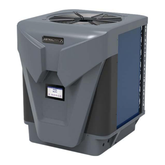
Top Discharge
Inverter Heat Pumps
TOP DISCHARGE
INVERTER HEAT PUMPS
Installation & Instruction manual
The appliance is not intended for use by young children or infrm persons without supervision. Please ensure that
3/08/2017
Advertisement

Subscribe to Our Youtube Channel
Related Manuals for fluidra Astral Pool IHPt127

Summary of Contents for fluidra Astral Pool IHPt127
- Page 1 INSTALLATION AND OPERATING INSTRUCTIONS INSTALLATION AND OPERATING INSTRUCTIONS Top Discharge Inverter Heat Pumps TOP DISCHARGE INVERTER HEAT PUMPS Installation & Instruction manual The appliance is not intended for use by young children or infrm persons without supervision. Please ensure that 3/08/2017...
-
Page 3: Table Of Contents
CONTENTS 1. Preface 2. Specifications 2.1 Performance Data of Swimming Pool Heat Pump Unit 2.2 Dimensions for Swimming Pool Heat Pump Unit 3. Installation and Connectio n Installation illustration Swimming Pool Heat Pumps Location 3.3 How Close to Your Pool? 3.4 Swimming Pool Heat Pumps Plumbing 3.5 Swimming Pool Heat Pumps Electrical Wiring 3.6 Initial Start-up of the Unit... - Page 4 1. PREFACE In order to provide our customers with quality, reliability and versatility, this product has been made to strict production standards. This manual includes all the necessary information about installation, debugging, discharging and maintenance. Please read this manual carefully before you open or maintain the unit. The manufacture of this product will not be held responsible if someone is injured or the unit is damaged, as a result of improper installation, debugging, or unnecessary maintenance.
- Page 5 IHPt127 IHPt168 IHPt246 Product Code Advised pool volume(m 30-60 40-75 50-100 Operating air temperature ( (-15~43) Air 27 Water 26 Humid. 80% Heating Capacity(kW) 2.8~12.7 3.9~16.8 5.9~24.6 Heating Capacity(Btu) 9520~43180 13300~57120 20 060~83460 Consumed power (kW) 0.22~2.2 0.31~2.98 0.47~4.94 5.77~12.73 5.
- Page 6 ①50 200 120 IHPt127 IHPt168 IHPt246 Dimensions(L/W/H)(mm) 723 835 865 723 835 865 770 990 970...
- Page 7 Option to plumb with separate water pump Where the heat pump is installed in the filtration circuit, the heater should always be installed after the pump and filter. The water connections are located on the right hand side of the heater. The inlet and outlet are clearly marked. Water connections supplied are for 50mm PVC glue in plumbing.
- Page 9 40mm...
-
Page 10: Installation And Connection
3. INSTALLATION AND CONNECTION 3.5 Swimming Pool Heat Pumps Electrical Wiring NOTE: Although the unit heat exchanger is electrically isolated from the rest of the unit, it simply prevents the flow of electricity to or from the pool water. Grounding the unit is still required to protect you against short circuits inside the unit. -
Page 11: Color Screen Wire Controller Interface Introduction
4.1 Color screen wire controller interface introduction 1Maininterface 4.1.1 9 09 DEC 2017 ⑧ ① ② ③ ④ ⑤ ⑥ ⑦ 4.1. 2 Button Description The button function Name ① Press to start t off the unit ON/OFF /shu ② Click to lock the screen Input to unlock the... -
Page 12: Color Screen Wire Controller Function Introduction
4.2 Color screen wire controller function introduction 4.2. 1Booting and shutdown As shown in figure 1 ① In shutdown status, click then the unit will be booted ① In booting status, click then the unit will be shut down 2 Mode switch and target temperature Setting 2 1 Mode switch In the main interface, click mode button or inlet water temperature setting button, interface displays as follows:... - Page 13 4.2.3 Clock setting In the main interface, click on the clock Settings button, interface displays as follo ① ② 2.3.1 The operation of time setting ① Click on the time Settings button , interface displays as follows: Click the value to set time directly, the click confirm button to save the Settings.
- Page 14 2.3.2 The operation of timing setting ② Click the timing set button to enter timing setinterface. ① ② ③ ④ Name Button color Button function ① Start: green Timing start Click this button to start or end End: gray timing start setting function button ②...
- Page 15 4.2.4 Silent setting and silent timing setting Click the silent setting button ,and the interface displays as follows: 09 DEC 2017 ① ② 2.4.1 The silent button ① Click the silent button , the unit will enter the silent mode, and interface displays as follows: 09 DEC 2017 ①...
- Page 16 2.4.2 Timing silent function setting ② Click timing silent button , and interface displays as follows: ① ② ③ ④ Function Name Color ① Used: red Timing silent off Click to use or unuse timing Unused:gray off function ② Use:green Click to use or unuse timing Timing silent on Unused:gray...
- Page 17 4.2.5 History of the fault In the main interface click fault display key, interface displays as follows: Fault time day - month - year The fault name Fault code hour:min If no failure, main interface displays static " " " " ", When fault occurs,the fault icon will flash between the "...
- Page 18 4.2.7 Temperature curve In the main interface, click the curve display button, interface displays as follows: 2.7.1 Temperature recording curve is as follows: 2.7.2 Comp.Frequency curve Temperature curve automatically updates every one hour, and the curve record can be stored for 60 days; Start from the latest curve saved time, if power is off and curve data collecting time is less than one hour, the data in this period will not be saved;...
-
Page 19: Parameter List And Breakdown Table
4.USAGE AND OPERATION 4.3 Parameter list and breakdown table (1) Electronic control fault table Can be judged according to the remote controller failure code and troubleshooting Fault Reason Elimination methods Protect/fault display Standby Normal boot The temp. Sensor is broken Inlet Temp. - Page 20 4.USAGE AND OPERATION Frequency conversion board fault table: Fault Reason Elimination methods Protection/fault display Recovery after the 150s MOP drive alarm Drv1 MOP alarm Frequency conversion board and main Check the communication connection Inverter offline board communication failure Recovery after the 150s IPM modular protection IPM protection Check the measuring voltage check...
- Page 21 OUT1 AC-L AC-N OUT3 OUT2 OUT5 OUT4 FUSE PC1002 485_B1 485_A1 485_B2 485_A2...
-
Page 23: Maintenance And Inspection
5. MAINTENANCE AND INSPECTION Check the water supply device and the release often. You should avoid the condition of no water or air entering into system, as this will influence unit's performance and reliability. You should clear the pool/spa filter regularly to avoid damage to the unit as a result of the dirty of clogged filter. - Page 24 6.APPENDIX 6.1 Caution 8 Warning 1. The unit can only be repaired by qualified installer centre personnel or an authorised dealer(for Europe market). 2. This appliance can used by children aged from 8 years and above and persons with reduced physical, sensory or mental capabilities or lack of experience and knowledge if they have been given supervision or instruction concerning use of the appliance in a safe way and understand the hazards involved(for Europe market).
- Page 25 6.APPENDIX 6.2 Cable specification (1) Single phase unit Nameplate Creepage protector Signal line maximum Phase line Earth line current No more 2x1.5mm 1.5mm than 10A 30mA less than 0.1 sec 2.5mm 2x2.5mm 30mA less than 0.1 sec 10~16A 2x4mm 30mA less than 0.1 sec ~25A 2x6mm 30mA less than 0.1 sec...
- Page 26 Note:...
- Page 28 20000-231607 sales@fluidra.com www.astralpool.com.au Fluidra Group Australia Pty Ltd 219 Woodpark Road Smithfield. N.S.W. 2164 ABN 87 002 641 965...
Need help?
Do you have a question about the Astral Pool IHPt127 and is the answer not in the manual?
Questions and answers