
Related Manuals for FireFlex TOTALPAC 3

Summary of Contents for FireFlex TOTALPAC 3
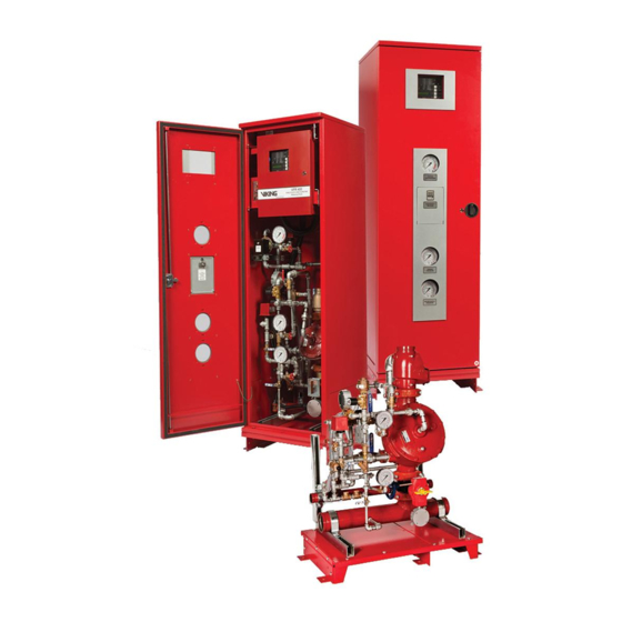
- Page 1 Advanced Integrated Fire Protection System ® OTAL Owner's Operation Maintenance Manual NTERLOCK REACTION YSTEM NEUMATIC RELEASE FM-076A-0-1C...
- Page 2 ® OTAL Page ii Integrated Fire Protection System & M WNER PERATION AINTENANCE ANUAL Copyright © 2020 F Systems Inc. All Rights Reserved Reproduction or use, without express written permission from F Systems Inc, of any portion of this manual is prohibited. While all reasonable efforts have been taken in the preparation of this manual to assure its accuracy, F Systems Inc assumes no liability resulting from any errors or omissions in this manual, or from the use of the information contained herein.
-
Page 3: Table Of Contents
® OTAL Page iii Integrated Fire Protection System & M WNER PERATION AINTENANCE ANUAL Table of Contents Non Interlock Preaction System - Pneumatic Release General Section ......................Section 1- General description 2- Listings and approvals 3- Applicable standards 4- Environment 5- Features 6- Configuration description 7- System release... - Page 4 ® OTAL Page iv Integrated Fire Protection System & M WNER PERATION AINTENANCE ANUAL This page is left intentionally blank. FM-076A-0-1C...
-
Page 5: General Section
® OTAL Page 1 of 2 Integrated Fire Protection System General Section - Non Interlock Preaction System - Pneumatic Release 1- General description ® This T 3 integrated fire protection system by Here is the list of Listings & Approvals it meets: OTAL Systems Inc. -
Page 6: 6- Configuration Description
® OTAL Page 2 of 2 Integrated Fire Protection System General Section - Non Interlock Preaction System - Pneumatic Release 5- Features 6- Configuration description ® ® The T 3 unit is superior to many other products 3 preaction system is built around the Viking OTAL OTAL which are actually available on the fire protection market. -
Page 7: Mechanical Section
® OTAL Page 1 of 8 Integrated Fire Protection System Mechanical Section - Non Interlock Preaction System - Pneumatic Release 1- Installation, operation & maintenance instructions 1.2 Preliminary inspection before placing the system in Note: Numbers indicated between brackets refer to figure 1 service DETAILED SYSTEM TRIM SCHEMATICS from this section and section... -
Page 8: Placing The System In Service
® OTAL Page 2 of 8 Integrated Fire Protection System Mechanical Section - Non Interlock Preaction System - Pneumatic Release 1.4 System Operation 1.3 Placing the system in service 1.4.1 In the SET condition 1. Verify that the main water supply valve (D1) is CLOSED. Verify that the system has been properly drained. -
Page 9: Emergency Instructions
® OTAL Page 3 of 8 Integrated Fire Protection System Mechanical Section - Non Interlock Preaction System - Pneumatic Release 1.6 Placing the system back in service after operation 1.5 Emergency instructions 1. Verify that the system has been properly drained. Verify To take system out of service that all automatic sprinklers are set and/or inspector's test valve and system piping auxiliary drain valves are... - Page 10 ® OTAL Page 4 of 8 Integrated Fire Protection System Mechanical Section - Non Interlock Preaction System - Pneumatic Release 1.7 Inspections and tests 1.7.2 Pneumatic release piping network (pilot line) low air supervisory test NOTICE: The owner is responsible for maintaining the fire 1.
-
Page 11: Maintenance
® OTAL Page 5 of 8 Integrated Fire Protection System Mechanical Section - Non Interlock Preaction System - Pneumatic Release When trip testing is complete 1.8 Maintenance 1. Perform steps 1 through 5 of paragraph 1.5 EMERGENCY NOTICE: The owner is responsible for maintaining the fire INSTRUCTIONS to take the system out of service. -
Page 12: Normal Condition
® OTAL Page 6 of 8 Integrated Fire Protection System Mechanical Section - Non Interlock Preaction System - Pneumatic Release 1.8.3 Semi-annually 2- Non interlock preaction system with pneumatic release 1. Main water supply valve (D1) switch shall be operated to verify the switch actuation upon movement of the hand wheel. - Page 13 ® OTAL Page 7 of 8 Integrated Fire Protection System Mechanical Section - Non Interlock Preaction System - Pneumatic Release Figure 1 - Detailed system trim schematic Typical non interlock preaction system with pneumatic release (3" (80 mm) system shown) FIELD CONNECTION TO SPRINKLER PIPING NETWORK TO RELEASE SYSTEM TRIM...
- Page 14 ® OTAL Page 8 of 8 Integrated Fire Protection System Mechanical Section - Non Interlock Preaction System - Pneumatic Release This page is left intentionally blank. FM-076A-0-41C...
-
Page 15: Trim Options
® OTAL Page 1 of 2 Integrated Fire Protection System Trim Options Preaction trim options 1. Shut-off valve & sight glass 2. Fire department connection The shut-off valve & sight glass option is intended to be The fire department connection option consists of a used for applications where testing of the system operation grooved tee fitting installed at the outlet of the deluge without filling the sprinkler piping network is desirable and... -
Page 16: 3- Semi And Full Flanged Option
® OTAL Page 2 of 2 Integrated Fire Protection System Trim Options 3. Semi and full-flanged option 4. Anti-column device option ® When required by the user, T 3 unit can be The model LD-1 anti-column device is an optional trim OTAL provided in either a semi-flanged of full flanged component designed for use with preaction sprinkler... - Page 17 ® OTAL Page 1 of 12 Integrated Fire Protection System Air Supply - Preaction System 1. Cabinet Air Supplies 1.2 Air supply Style "B" (refer to figure 3) Preaction sprinkler system using pressure supervisory or releasing purposes is provided with either Used only for the sprinkler piping network of preaction internal or external supervised air supply.
- Page 18 ® OTAL Page 2 of 12 Integrated Fire Protection System Air Supply - Preaction System 2. Operation 2.1 Air supply Style "A" (refer to figure 2) 2.2 Air supply Style "B" or "C" (refer to figure 3 or 4) To apply air supply To apply air supply Establish AC power for the air compressor by activating 1.
- Page 19 ® OTAL Page 3 of 12 Integrated Fire Protection System Air Supply - Preaction System 3. Maintenance and inspection 3.2 Air supply Style "B" or C" (refer to figure 3 or 4) Important : Advise local authorities of the necessary work The Viking Model D-2 APMD (air pressure maintenance over the fire protection equipment.
-
Page 20: Air Supply
® OTAL Page 4 of 12 Integrated Fire Protection System Air Supply - Preaction System Table 2 - Water pressure up to 175 PSI (1207 kPa) Air supply Compressor Compressor Low air System type Style regulator start stop supervisory 30 PSI 35 PSI 25 PSI (207 kPa) - Page 21 ® OTAL Page 5 of 12 Integrated Fire Protection System Air Supply - Preaction System Figure 2 - Air supply Style "A" Pressure relief valve This section replaced by Dehydrator option (when used) Copper tubing (plugged with SureFire or non interlock preaction trim) TO OPTIONAL ACCELERATOR (plugged when not used) TO DRAIN COLLECTOR...
- Page 22 ® OTAL Page 6 of 12 Integrated Fire Protection System Air Supply - Preaction System Figure 3 - Air supply Style "B" This section replaced by Dehydrator option (when used) (plugged with SureFire or non interlock preaction trim) Contractor external Air or Nitrogen connection TO PNEUMATIC ACTUATOR...
- Page 23 ® OTAL Page 7 of 12 Integrated Fire Protection System Air Supply - Preaction System Figure 4 - Air supply Style "C" APMD for pilot line release only. To pneumatic release piping network Contractor external air or Nitrogen connection To optional accelerator To pneumatic actuator (plugged when not used) FM-061H-0-120B...
- Page 24 ® OTAL Page 8 of 12 Integrated Fire Protection System Air Supply - Preaction System Figure 5 - Air supply Style "D" Air supply connection for external air supply (plugged with SureFire or non interlock preaction trim) Contractor external air or Nitrogen connection TO PNEUMATIC TO OPTIONAL ACCELERATOR...
-
Page 25: 4- Air Supply Options
® OTAL Page 9 of 12 Integrated Fire Protection System Air Supply - Preaction System 4. Air supply options 4.1 Dehydrator Operation of dehydrator Viking dehydrator is a manually regenerated The dehydrator directs the incoming air down through the desiccant-type air dryer. The desiccant acts as a moisture silica gel desiccant. - Page 26 ® OTAL Page 10 of 12 Integrated Fire Protection System Air Supply - Preaction System Figure 6 - Dehydrator option for air supply Style "A" From air supply Dehydrator bowl To sprinkler riser Desiccant sight glass FM-061H-0-124B-1 Figure 7 - Dehydrator option for air supply Style "B" To air Style "B"...
- Page 27 ® OTAL Page 11 of 12 Integrated Fire Protection System Air Supply - Preaction System 4.2 Accelerator To reset the accelerator device The Viking Model E-1 accelerator is a quick-opening Make sure the system is properly drained and reset. device featuring automatic reset. The Viking Model E-1 Observe the upper chamber pressure of the accelerator.
- Page 28 ® OTAL Page 12 of 12 Integrated Fire Protection System Air Supply - Preaction System Figure 8 - Accelerator Option For preaction system and pilot line release Upper chamber pressure gauge Accelerator Isolation valve To air line Drain plug FM-061H-0-125B FM-076A-0-86C...
-
Page 29: Control Section
® OTAL Page 1 of 2 Integrated Fire Protection System Control Section 1. Remotely controlled unit without release control panel 1.1 Product description Figure 1 – Cabinet layout ® The T 3 preaction unit is provided without release OTAL control panel. A field wiring electrical junctions box is integrated with the cabinet for connection of pressure switches, supervisory switches, etc. - Page 30 ® OTAL Page 2 of 2 Integrated Fire Protection System Control Section Figure 2 - Junctions box layout for system without release control panel AC POWER POWER LIMITED CIRCUITS 120VAC, 50/60Hz or TBB Terminals 220/240VAC, 50/60Hz All conduits are installed by the Contractor through 1/2"...
-
Page 31: Electrical Section
® OTAL Page 1 of 2 Integrated Fire Protection System Electrical Section - Non Interlocked Preaction System - Pneumatic Release 1. Remotely controlled configuration ® This T 3 unit has been provided without an OTAL integrated control panel since all internal supervisory and releasing devices are to be connected and supervised from a remote releasing control panel. - Page 32 ® OTAL Page 2 of 2 Integrated Fire Protection System Electrical Section - Non Interlocked Preaction System - Pneumatic Release This page is left intentionally blank. FM-076A-0-61C...
-
Page 33: Dimensional Data & Cabinet
® OTAL Page 1 of 8 Integrated Fire Protection System Dimensional Data & Cabinet ® 1- Cabinet for TotalPac 3 unit ® The TotalPac 3 unit cabinet is made of sturdy 14 gauge ® IMPORTANT ! TotalPac 3 unit is NOT designed to be steel. - Page 34 ® OTAL Page 2 of 8 Integrated Fire Protection System Dimensional Data & Cabinet Figure 1 - Cabinet and inlets/outlets dimensions TBA, TBB & TBC TBA & TBC OPTIONAL SHUT-OFF VALVE ØB OPTIONAL FIRE DEP'T CONNECTION OUTLET (DRILLED ONLY WHEN ORDERED) ØC DRAIN - SCH.40 GROOVED OUTLET...
- Page 35 ® OTAL Page 3 of 8 Integrated Fire Protection System Dimensional Data & Cabinet Figure 2 - Floor anchoring dimensions Table 3 - Floor anchoring dimensions Unit size 1½ 25" 15" 5" (127mm) 5" (127mm) (635mm) (380mm) (40mm) 2" 25" 15"...
- Page 36 ® OTAL Page 4 of 8 Integrated Fire Protection System Dimensional Data & Cabinet Figure 5 - Open drain details for single unit Table 5 - Manifold dimensions Unit size Unit OTAL Shown Without 1½ 8¾" 13¾" 2" (222mm) (350mm) (50mm) Front Doors (40mm)
- Page 37 ® OTAL Page 5 of 8 Integrated Fire Protection System Dimensional Data & Cabinet ® 2- Skid mounted TotalPac 3 unit ® Table 1 - System weight on skid The TotalPac 3 unit skid base is made of sturdy 11 gauge and 7 gauge steel.
- Page 38 ® OTAL Page 6 of 8 Integrated Fire Protection System Dimensional Data & Cabinet Figure 7 - Skid and inlets/outlets dimensions (figure is shown without trim for clarity) ØB A = Main Inlet Manifold Diameter B = Sprinkler Riser Diameter C = Drain Manifold Diameter Optional Shut-off Valve Optional Fire Dep't Connection...
- Page 39 ® OTAL Page 7 of 8 Integrated Fire Protection System Dimensional Data & Cabinet Figure 8 - Floor anchoring dimensions Table 8 - Floor anchoring dimensions Unit size 5" (127mm) 5" (127mm) 1½" 25" 15" (635mm) (380mm) (40mm) 2" 25" 15"...
- Page 40 ® OTAL Page 8 of 8 Integrated Fire Protection System Dimensional Data & Cabinet Figure 10 - Open drain details for single unit Table 10 - Manifold dimensions Unit Drain Pipe (dia. = C) Unit size Air Gap 1½" 8¾" 13¾"...
-
Page 41: Limited Warranty
Manufacturer with respect to its Tel.: (450) 437-3473 products. This warranty shall not be modified, unless such Fax: (450) 437-1930 modification is made in writing by an executive officer of Toll Free: (866) 347-3353 the Manufacturer. Website: www.fireflex.com FM-076A-0-96C... - Page 42 ® OTAL Page 2 of 2 Integrated Fire Protection System Limited Warranty User Notes FM-076A-0-96C...
Need help?
Do you have a question about the TOTALPAC 3 and is the answer not in the manual?
Questions and answers