Advertisement
Quick Links
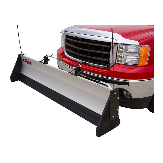
INSTALLATION INSTRUCTIONS
Thank you for purchasing SNOWSPORT
HD Utility Plow. Agri-Cover, Inc. proudly
®
manufactured this snowplow using superior quality materials and workmanship. With
proper care, your snowplow will provide years of service and enjoyment.
NOTICE TO INSTALLER: Even if familiar with product, read instructions prior to
installation as improvements may be made without notice. Always handle components
with care. If you have questions or problems, have serial number ready and call
customer service. When done, these instructions must be given to the consumer.
NOTICE TO CONSUMER: Before using snowplow, read safety and operation sections.
Save these instructions for future reference.
FOR YOUR RECORDS
DATE PURCHASED:
WHERE PURCHASED:
SERIAL NUMBER:
(Located on back of snowplow blade)
Questions? 800-689-6612
agricover.com
Advertisement

Related Manuals for aci SNOWSPORT HD Utility Plow

Summary of Contents for aci SNOWSPORT HD Utility Plow
- Page 1 INSTALLATION INSTRUCTIONS Thank you for purchasing SNOWSPORT HD Utility Plow. Agri-Cover, Inc. proudly ® manufactured this snowplow using superior quality materials and workmanship. With proper care, your snowplow will provide years of service and enjoyment. NOTICE TO INSTALLER: Even if familiar with product, read instructions prior to installation as improvements may be made without notice.
- Page 2 PREPARATION Unpack snowplow components. For additional installation assistance, go to mysnowsport.com for install and operation videos. TOOLS NEEDED COMPONENTS • (2) Short 2x4 sections • (2) Box ends • Drill with 5/16” bit • (2) Slide hinges • 9/16” socket with ratchet or impact driver/ •...
-
Page 3: Safety Information
SAFETY INFORMATION • Always follow vehicle manufacturer recommendations for snowplowing. • Always exercise safety, courtesy and common sense. • Always know the terrain before plowing. • Always wear your seat belt. • Always look where you are going when backing up, don't rely on mirrors or back up cameras. -
Page 4: Parts Diagram
PARTS DIAGRAM Blade marker Lift handle End plate Box end... - Page 5 Aluminum blade Slide hinge Rubber cutting edge Quick pin Push frame Swivel pin Set collar Shim Hair pin Receiver pin...
- Page 6 1: INSTALLING PUSH FRAME NOTE: We recommend performing this Push frame step with two people. One person holds the Mounting push frame to the interceptor while another (4) 1/2” bracket performs the installation. x 4” Hex bolts A. Insert interceptor into receiver with push (8) Flat frame mounting bracket facing up and secure washers...
- Page 7 1: INSTALLING PUSH FRAME (Continued) F. If push frame leans toward front of vehicle, Shim remove upper bolts, insert one or two shims at top and reinsert bolts. G. If push frame leans away from front of vehicle, remove lower bolts and insert one or two shims at bottom and reinsert bolts.
- Page 8 2: ASSEMBLING SNOWPLOW NOTE: Rubber cutting edge should be room temperature before assembling. A. Align groove on rubber cutting edge with groove in lower aluminum blade. B. Slide rubber cutting edge into matching channel of lower aluminum blade and center. TIP: Apply soapy water solution to top of rubber cutting edge and aluminum blade mounting channel for easier assembly.
- Page 9 2: ASSEMBLING SNOWPLOW (Continued) ELECTRIC WINCH: Slide (2) weld nuts with flat side up through top channel to mid-point on plow. E. Align middle holes on slide hinge with factory marks on back of blade. Insert (2) square nuts with flat side facing up in top and bottom channels of blade. Slide nuts to slide hinge and align with holes.
- Page 10 2: ASSEMBLING SNOWPLOW (Continued) I. Use slide hinges as templates to drill (4) 5/16” holes through back layer of aluminum at each factory marked location. J. At tongue and groove joint, drill 5/16" hole through back layer of aluminum at factory mark in v-groove on each end of blade.
- Page 11 2: ASSEMBLING SNOWPLOW (Continued) M. Center rubber cutting edge with lower aluminum blade. N. Drill 5/16” pilot hole at factory mark in groove on each end of blade, drill only through first layer of aluminum and into rubber. O. Turn 3/8" x 1" self-threading flange bolts into 5/16" pilot holes and tighten. 3/8"...
- Page 12 2: ASSEMBLING SNOWPLOW (Continued) R. Insert (2) square nuts with flat side up into top channel. S. Turn hex jam nut with flange side facing down onto threaded base of blade marker and align with hole on lift handle. Bolt blade marker and handle to blade using square nut in channel.
- Page 13 2: ASSEMBLING SNOWPLOW (Continued) V. Attach rubber box end and metal end plate to end of blade with (4) 3/8" x 2-1/2" hex bolts. W. Tighten all bolts until rubber begins to compress to blade. Insert 3/8" x 1-3/4" hex bolt to tighten bottom of rubber to bottom of end plate.
- Page 14 OPERATING INSTRUCTIONS TO LOWER FOR PUSHING SNOW Step behind blade and remove quick pin. Lift one side of blade out of retainer groove until slide hinge fits over the push frame bar, then lower blade to ground. Secure with quick pin. Repeat for opposite side of blade. TO PUSH SNOW Drive forward slowly, blade will engage for pushing.
-
Page 16: Manufacturer's Limited Warranty
MANUFACTURER’S LIMITED WARRANTY Agri-Cover, Inc. extends the following Limited Warranty on its SNOWSPORT HD Utility ® Plow: Agri-Cover, Inc. warrants its SNOWSPORT HD Utility Plow to be free from defects in ® material and workmanship under normal use for one (1) year from date of manufacture unless accompanied by proof of purchase and separately warrants only the rubber blade portion of the SNOWSPORT HD Utility Plow to be free from defects in material and workmanship...
Need help?
Do you have a question about the SNOWSPORT HD Utility Plow and is the answer not in the manual?
Questions and answers