Table of Contents
Advertisement
EPAD2/CPAD2/CPAD3
SERIES MODULES
TECHNICAL
REFERENCE
MANUAL
WELCOME TO
THE WORLD OF
DEWETRON!
Congratulations on your new device! It
will supply you with accurate, complete
and reproducible measurement results
for your decision making.
Look forward to the easy handling and
the flexible and modular use of your
DEWETRON product and draw upon
more than 25 years of DEWETRON
expertise in measurement engineering.
CUSTOMIZED
ISO9001
EN ISO 14001
MODULAR
COMPETENT
COMMITTED
APPROVED
Advertisement
Table of Contents

Subscribe to Our Youtube Channel
Related Manuals for Dewetron EPAD2 Series


Summary of Contents for Dewetron EPAD2 Series
- Page 1 Look forward to the easy handling and the flexible and modular use of your DEWETRON product and draw upon more than 25 years of DEWETRON expertise in measurement engineering. CUSTOMIZED MODULAR COMPETENT...
- Page 2 Copyright © DEWETRON GmbH This document contains information which is protected by copyright. All rights are reserved. Reproduction, adaptation, or translation without prior written permission is prohibited, except as allowed under the copyright laws. All trademarks and registered trademarks are acknowledged to be the property of their owners.
-
Page 3: Table Of Contents
Warranty Information ……………………………………………………………………… 5 Support ……………………………………………………………………………………… 5 Printing History ……………………………………………………………………………… 5 Safety symbols in the manual …………………………………………………………… 6 Safety instructions for all DEWETRON systems ……………………………………… 7 Environmental Considerations …………………………………………………………… 8 General module information Calibration information …………………………………………………………………… 9 General module specifications …………………………………………………………… 9 EPAD2-USB Module Module specifications ………………………………………………………………………... - Page 4 Table of content EPAD2/CPAD2-V8 Module Module specifications ……………………………………………………………………… 29 Push button ………………………………………………………………………………… 31 Connection ………………………………………………………………………………… 31 Programming information ………………………………………………………………… 32 EPAD2/CPAD2-V8-L1B Module Module specifications ……………………………………………………………………… 33 Push button ………………………………………………………………………………… 35 Connection ………………………………………………………………………………… 35 Programming information ………………………………………………………………… 35 EPAD2/CPAD2-RTD8-L1B Module Module specifications ……………………………………………………………………… 37 Push button …………………………………………………………………………………...
- Page 5 Table of content Installing CPAD2/CPAD3 modules Installing CPAD2/CPAD3 modules in DEWESoft 7.x …………………………………… 55 Installing EPAD2 modules Installing EPAD2 modules in DEWESoft 7.x (except EPAD2-AO4, EPAD2-USB) ……………………………………………………………………………… 58 Max. cable length & modules per CAN bus Power supply considerations Module reset EPAD2 Module reset: ………………………………………………………………………...
- Page 6 Table of content...
-
Page 7: General Information, Safety Instructions
Warranty Information A copy of the specific warranty terms applicable to your DEWETRON product and replacement parts can be obtained from your local sales and service office. Support For any support please contact your local distributor first or DEWETRON directly. -
Page 8: Safety Symbols In The Manual
Failure to comply with these precautions or with specific warnings elsewhere in this manual violates safety standards of design, manufacture, and intended use of the product. DEWETRON Elektronische Messgeraete Ges.m.b.H. assumes no liability for the customer’s failure to comply with these requirements. -
Page 9: Safety Instructions For All Dewetron Systems
DO NOT substitute parts or modify equipment: Because of the danger of introducing additional hazards, do not install substitute parts or perform any unauthorized modification to the product. Return the product to a DEWETRON sales and service office for service and repair to ensure that safety features are maintained. -
Page 10: Environmental Considerations
This symbol indicates that this system complies with the European Union’s requirements according to Directive 2002/96/EC on waste electrical and electronic equipment (WEEE). Please find further informations about recycling on the DEWETRON web site www.dewetron.com Restriction of Hazardous Substances This product has been classified as Monitoring and Control equipment, and is outside the scope of the 2002/95/EC RoHS Directive. -
Page 11: General Module Information
General module information General module information Calibration information All DEWETRON modules are calibrated at 25 °C and meet their specifications when leaving the factory. The time interval for recalibration depends on environmental conditions. Typically, the calibration should be checked once a year. - Page 12 Notes...
-
Page 13: Epad2-Usb Module
The EPAD2-USB reads the data from connected EPAD2 modules and provides them via native USB interface to the PC/Laptop or any other DEWETRON instrument. The independently working EPAD2-USB module also offers the possibility to create a virtual COM interface in Microsoft Windows to be used with any ®... - Page 14 EPAD2-USB Module Dimensions* 6,5x2 Back max.4,5 mm thread reach * Dimensions in mm (1 inch = 25.4 mm)
-
Page 15: Connection
The Power LED is only active when connected to a USB port of your PC/Laptop and NOT when connected to the external power supply! EPAD interface connector This connector can be used to connect the EPAD2-USB to other EPAD2 series modules Pin assignment EPAD2: RS-485 (A) -
Page 16: Installing Usb Drivers
Before connecting the EPAD2-USB device to your PC/Laptop make sure to install the USB drivers for your instrument. To install the corresponding drivers insert the DEWETRON Install Media USB drive shipped with your system and klick <start.exe>. Navigate to "Drivers" > "USB & RS485" > "dewetron_usb". -
Page 17: How To Setup Epad2-Usb In Dewesoft
EPAD2-USB Module Proceed with "OK". Figure 4: Summary of added COM ports used by the driver Now you have successfully setup your EPAD2-USB in DASYLab. How to setup EPAD2-USB in DEWESoft™ First of all, a valid DEWESoft™ license is required to run EPAD modules in DEWESoft™ such as DS-7-LT or higher. - Page 18 EPAD2-USB Module Notes...
-
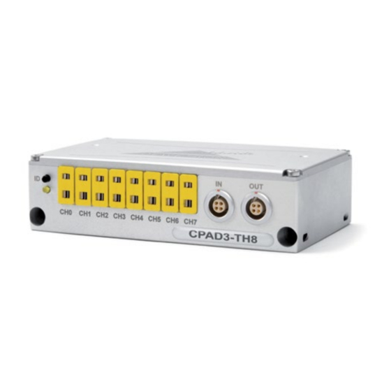
Page 19: Cpad3-Th8-X Module
CPAD3-TH8-x Module 8 channel thermocouple amplifier Intelligent amplifier with integrated A/D conversion 8 input channels for thermocouples Available thermocouple types: xPAD2-TH8-x: K, J, T standard type xPAD2-TH8-UNIVERSAL: Universal type Standard CAN interface Module specifications CPAD3-TH8-x Input channels 8 isolated Thermocouple Channels Input signals CPAD3-TH8-x Thermocouple type K, J, T (others on request) - Page 20 CPAD3-TH8-x Module Dimensions* 6.5x2 rear view max. 4.5 mm thread reach * Dimensions in mm (1 inch = 25.4 mm)
-
Page 21: Push Button
CPAD3-TH8-x Module Push button Use the ID button to define the module address via software. Detailed information how to use the button is available in chapter: "Module reset". Connection 8x thermocouple connector State LED ID button 2x xPAD2/CPAD3 interface connector Thermocouple connectors The CPAD3-TH8-x module supports up to 8 thermocouples. -
Page 22: Programming Information
CPAD3-TH8-x Module The CPAD3-TH8-x comes with an integrated cold junction compensation sensor with an absolute accuracy of ±0.2 °C. In order to archieve this accuracy the sensor has to be connected for at least 2 minutes to the thermocouple connector (CJC equilibrium time). NOTE: With the CPAD3-TH8-UNIVERSAL it is possible to get almost the same accuracy under laboratory conditions compared to the CPAD3 with dedicated TC-connectors. -
Page 23: Cpad3-V8 Module
CPAD3-V8 Module 8 channel voltage amplifier Intelligent amplifier with integrated 20-bit A/D conversion 8 channel isolated data acquisition Standard CAN interface Module specifications CPAD3-V8 Input channels 8 isolated voltage input channels Input ranges Physical input range: ±50 V Software selectable: ±100 mV, ±500 mV, ±1 V, ±2.5 V, ±5 V, ±10 V Resolution 100 µV for all ranges DC accuracy... - Page 24 CPAD3-V8 Module Dimensions* 6.5x2 rear view max. 4.5 mm thread reach * Dimensions in mm (1 inch = 25.4 mm)
-
Page 25: Push Button
CPAD3-V8 Module Push button Use the ID button to define the module address via software. Detailed information how to use the button is available in chapter: "Module reset". Connection Voltage input connector State LED ID button 2x xPAD2/CPAD3 interface connector Voltage input connector The CPAD3-V8 module offers 8 differential voltage input channels. -
Page 26: Programming Information
CPAD3-V8 Module Programming information The CPAD3-V8 programming information is available in the DEWE-MODULES Programmers Reference Manual. -
Page 27: Epad2/Cpad2-Th8-X Module
EPAD2/CPAD2-TH8-x Module 8 channel thermocouple amplifier Intelligent amplifier with integrated A/D conversion 8 input channels for thermocouples Available thermocouple types: xPAD2-TH8-x: K, J, T standard type xPAD2-TH8-UNIVERSAL: Universal type RS-485 or CAN interface Module specifications xPAD2-TH8-x Input channels 8 isolated Thermocouple Channels Input signals xPAD2-TH8-x Thermocouple type K, J, T (others on request) - Page 28 EPAD2/CPAD2-TH8-x Module Dimensions* 6.5x2 rear view max. 4.5 mm thread reach * Dimensions in mm (1 inch = 25.4 mm)
-
Page 29: Push Button
EPAD2/CPAD2-TH8-x Module Push button Use the ID button to define the module address via software. Detailed information how to use the button is available in chapter: "Installing EPAD2/CPAD2 modules in DEWESoft, Module reset". Connection 8x thermocouple connector State LED ID button 2x xPAD2 interface connector Thermocouple connectors The xPAD2-TH8-x module supports up to 8 thermocouples. -
Page 30: Programming Information
EPAD2/CPAD2-TH8-x Module The xPAD2-TH8-x comes with an integrated cold junction compensation sensor with an absolute accuracy of ±0.2 °C. In order to archieve this accuracy the sensor has to be connected for at least 2 minutes to the thermocouple connector (CJC equilibrium time). NOTE: With the xPAD2-TH8-UNIVERSAL it is possible to get almost the same accuracy under laboratory conditions compared to the xPAD2 with dedicated TC-connectors. -
Page 31: Epad2/Cpad2-V8 Module
EPAD2/CPAD2-V8 Module 8 channel voltage amplifier Intelligent amplifier with integrated 24-bit A/D conversion 8 channel isolated data acquisition RS-485 or CAN interface Module specifications xPAD2-V8 Input channels 8 isolated voltage input channels Input ranges Physical input range: ±50 V Software selectable: ±100 mV, ±500 mV, ±1 V, ±2.5 V, ±5 V, ±10 V Resolution 10 µV for all ranges DC accuracy... - Page 32 EPAD2/CPAD2-V8 Module Dimensions* 6.5x2 rear view max. 4.5 mm thread reach * Dimensions in mm (1 inch = 25.4 mm)
-
Page 33: Push Button
EPAD2/CPAD2-V8 Module Push button Use the ID button to define the module address via software. Detailed information how to use the button is available in chapter: "Installing EPAD2/CPAD2 modules in DEWESoft, Module reset". Connection Voltage input connector State LED ID button 2x xPAD2 interface connector Voltage input connector The xPAD2-V8 module offers 8 differential voltage input channels. -
Page 34: Programming Information
EPAD2/CPAD2-V8 Module Programming information The xPAD-V8 programming information is available in the DEWE-MODULES Programmers Reference Manual. -
Page 35: Epad2/Cpad2-V8-L1B Module
EPAD2/CPAD2-V8-L1B Module 8 channel voltage amplifier Intelligent amplifier with integrated 24-bit A/D conversion 8 channel isolated data acquisition RS-485 or CAN interface Module specifications xPAD2-V8-L1B Input channels 8 isolated voltage input channels Input ranges Physical input range: ±50 V Software selectable: ±100 mV, ±500 mV, ±1 V, ±2.5 V, ±5 V, ±10 V Resolution 10 µV for all ranges DC accuracy... - Page 36 EPAD2/CPAD2-V8-L1B Module Dimensions* 6.5x2 rear view max. 4.5mm thread reach * Dimensions in mm (1 inch = 25.4 mm)
-
Page 37: Push Button
EPAD2/CPAD2-V8-L1B Module Push button Use the ID button to define the module address via software. Detailed information how to use the button is available in chapter: "Installing EPAD2/CPAD2 modules in DEWESoft, Module reset". Connection Voltage input connectors State LED ID button 2x xPAD2 interface connector Voltage input connector The xPAD2-V8-L1B module offers 8 differential voltage input channels. - Page 38 EPAD2/CPAD2-V8-L1B Module Notes...
-
Page 39: Epad2/Cpad2-Rtd8-L1B Module
EPAD2/CPAD2-RTD8-L1B Module 8 channel Resistance Temperature Detector amplifier Amplifier with integrated 24-bit A/D conversion 8 isolated Resistance Temperature Detector channels RS-485 or CAN interface Module specifications xPAD2-RTD8-L1B Input channels 8 isolated Resistance Temperature Detector channels Input ranges Resistor: 0 to 999.99Ohm RTD: PT100(385);... - Page 40 EPAD2/CPAD2-RTD8-L1B Module Dimensions* 6.5x2 rear view max. 4.5mm thread reach * Dimensions in mm (1 inch = 25.4 mm)
-
Page 41: Push Button
EPAD2/CPAD2-RTD8-L1B Module Push button Use the ID button to define the module address via software. Detailed information how to use the button is available in chapter: "Installing EPAD2/CPAD2 modules in DEWESoft, Module reset". Connection RTD input connectors State LED ID button 2x xPAD2 interface connector RTD input connector The xPAD2-RTD8-L1B module offers 8 isolated Resistor Temperature Detector input channels. -
Page 42: Programming Information
EPAD2/CPAD2-RTD8-L1B Module Sensor connection 2-wire connection 4-wire connection 4-pin LEMO RTD sensor 4-pin LEMO RTD sensor connector connector SENSE+ SENSE+ EXC+ EXC+ EXC- EXC- SENSE- SENSE- housing housing Programming information The xPAD-RTD8-L1B programming information is available in the DEWE-MODULES Programmers Reference Manual. -
Page 43: Epad2/Cpad2-Th8-P Module
EPAD2/CPAD2-TH8-P Module 8 channel thermocouple and RTD amplifier Intelligent amplifier with integrated 24-bit A/D conversion 8 galvanically isolated input channels External CJC Automatic sensor block detection Signal connection via 25-pin SUB-D connector Supported breakout boxes: PAD-CB8-x-P2: standard thermocouple breakout box PAD-CB8-x-M: small size thermcouple breakout box PAD-CB8-RTD:... - Page 44 EPAD2/CPAD2-TH8-P Module Dimensions* 6.5x2 rear view max. 4.5 mm thread reach * Dimensions in mm (1 inch = 25.4 mm)
-
Page 45: General
EPAD2/CPAD2-TH8-P Module General To use the full power of the xPAD2-TH8-P module, a supported breakout box for RTD and thermocouple sensors should be ordered together with the module. Supported breakout boxes: PAD-CB8-x-P2 standard thermocouple breakout box PAD-CB8-x-M small size thermocouple box PAD-CB8-RTD RTD breakout box Push button... -
Page 46: Programming Information
EPAD2/CPAD2-TH8-P Module xPAD2 interface connector This connector can be used to connect the module to the EPAD-BASE2 module or other xPAD2 series Pin assignment EPAD2: Pin assignment CPAD2: RS-485 (A) CAN high RS-485 (B) CAN low Power supply (+) Power supply (+) 4 pin LEMO series Schematic connector... -
Page 47: Epad2/Cpad2-La8-L1B Module
EPAD2/CPAD2-LA8-L1B Module 8 channel high precision amplifier for 4 to 20 mA sensors Intelligent amplifier with integrated 24-bit A/D conversion 8 galvanically isolated input channels RS-485 or CAN interface Module specifications xPAD2-LA8-L1B Input channels 8 isolated current inputs Input range 0 to 20 mA, ±20 mA;... - Page 48 EPAD2/CPAD2-LA8-L1B Module Dimensions* 6.5x2 rear view max. 4.5mm thread reach * Dimensions in mm (1 inch = 25.4 mm)
-
Page 49: Push Button
EPAD2/CPAD2-LA8-L1B Module Push button Use the ID button to define the module address via software. Detailed information how to use the button is available in chapter: "Installing EPAD2/CPAD2 modules in DEWESoft, Module reset". Connection Current input connectors State LED ID button 2x xPAD2 interface connector LA input connector The xPAD2-LA module offers 8 isolated current input channels. -
Page 50: Signal Connection
EPAD2/CPAD2-LA8-L1B Module Signal connection Current measurement (4 to 20 mA loop) Connector Sensor Power supply + 4..20 mA Current + 4..20 mA output 50 Ω Current - Power supply - Loop powered sensor Connector Sensor 2-wire 4..20 mA Power supply + Output Current + 50 OHM... -
Page 51: Epad2-Ao4 Module
EPAD2-AO4 Module 4 channel analog output module 4 channel analog output RS-485 interface Module specifications EPAD2-AO4 Output channels 4 output channels Output modes Voltage output or current output; current sinking only Output ranges ±10 V; ±5 V; 0 to 5 V; 0 to 10 V; 0 to 20 mA;... - Page 52 EPAD2-AO4 Module Dimensions* 6.5x2 rear view max. 4.5 mm thread reach * Dimensions in mm (1 inch = 25.4 mm)
-
Page 53: Push Button
EPAD2-AO4 Module Push button The ID button is used to RESET the module. To reset the module just unplug all cables from the module. Press and hold the ID button. Plug-in the RS-485 to power up the module. Now the module is set to standard settings. - Page 54 EPAD2-AO4 Module Analog output connector The EPAD2-AO4 module offers 4 differential voltage/current output channels. Pin assignment: Channel 0 Channel 0 Channel 0 17 Reserved 17 Reserved 17 Reserved GNDi GNDi GNDi 18 Reserved 18 Reserved 18 Reserved Channel 1 Channel 1 Channel 1 19 Reserved 19 Reserved...
-
Page 55: Signal Connection
EPAD2-AO4 Module Signal connection Voltage output Connectors Current output Connectors max. 47 V EPAD2/CPAD2/CPAD3 series modules • Technical Reference Manual • Printing version 1.0.2 • October 04, 2016... - Page 56 EPAD2-AO4 Module Notes...
-
Page 57: Installing Cpad2/Cpad3 Modules
Installing CPAD2/CPAD3 modules Installing CPAD2/CPAD3 modules in DEWESoft 7.x NOTE: Installing CPAD3 modules in DEWESoft is exactly the same as installing any CPAD2 series modules! Figures within this chapter contain CPAD2 screenshots only. Activate CPAD2/CPAD3 modules Click on "Settings" > "Hardware Setup" > "CAN" Select the CAN device you are using Set the CAN Port you use for the CPAD to acknowledge Set the CAN Port to CPAD2/CPAD3 in the special devices section. - Page 58 Installing CPAD2/CPAD3 modules drag & drop Figure 2: configuring CPAD2/CPAD3 modules Unused modules do not send any data. The sample rate is 0. All modules listed in the "used modules" are automatically sorted by the module ID. By default the module ID is the serial number, but it could be changed by clicking on it. You can change the data format, the arbitration type and the baud rate in the configuration mode.
- Page 59 Installing CPAD2 modules Virtual CPAD2 modules If you remove a CPAD from the CAN bus it will not disappear but change into the virtual mode. They could be still used in the setup but will not show any data. Immediately when you connect them again they will deliver data again.
-
Page 60: Installing Epad2 Modules
Installing EPAD2 modules Installing EPAD2 modules in DEWESoft 7.x (except EPAD2-AO4, EPAD2-USB) Activate EPAD modules Click on "Settings" > "Hardware Setup" > "Analog" Select the used COM port from the list Check PAD modules in the Amplifier list Select the amount of EPAD you want to connect Figure 6: Activate EPAD modules Assign module address Connect the first EPAD to the RS-485 bus. - Page 61 Installing EPAD2 modules double click Figure 7: Assign module address Connecting more than one unaddressed module to the RS485 bus at the same time is not recommended. It might be necessary to do the addressing several times until all modules are on the correct address. In that case it is recommended to press the ID button on the module before you click on the “Fill”...
-
Page 62: Max. Cable Length & Modules Per Can Bus
Max. cable length & modules per CAN bus Maximum Cable Length and Modules per CAN Bus There are several parameters that have to be considered when building a CAN bus network with CPAD modules. Baud rate A higher baud rate allows a higher sample rate or using more CPADs. On the other hand, it reduces the maximum cable length. -
Page 63: Power Supply Considerations
Power supply considerations Power Supply considerations Depending on the power supply only a certain number of modules can be connected. If longer cables are used this number is reduced because of the cable resistance. Typical configurations: 12 V, 200 mA (DSUB-9 from ORION board) 5 m bus length max. -
Page 64: Module Reset
Module reset EPAD2 Module reset: If the Module could not be detected from the software anymore a possible reason could be that the module has been set to a different address or baud rate. With the reset function you can set the module back to its default settings: Baud rate: 9600 baud... -
Page 65: Mounting Examples
Mounting examples Mounting examples The EPAD2/CPAD2/CPAD3 modules are prepared for various mounting options: DIN rail Cable strap Bolt down For the mounting option "bolt down": two screws with 4.2 mm diameter are required. Stack For the mounting option "stack": two long M4 Allen head screws are required. -
Page 66: Configuration Examples
In each case the last DEWE-xPAD2 module has to be terminated! Note: Due to output resistance with longer cables an external DC power supply might be necessary. In this case, DEWETRON offers the CPAD-CBL-LD9-X-POW cable with two additional banana plugs for 7..40 V... -
Page 67: Configuration Example With Cpad2/Cpad3 Modules
In each case the last xPAD2/CPAD3 module has to be terminated! Note: Due to output resistance with longer cables an external DC power supply might be necessary. In this case, DEWETRON offers the CPAD-CBL-LD9-X-POW cable with two additional banana plugs for 7..40 V power supply. -
Page 68: Accessories & Options
Accessories Accessories & Options General accessories and options for xPAD2 modules EPAD-BASE2 Multifunction BASE module for connecting EPAD modules to USB - recognizes USB communication losses and reports them back to DEWESoft (native USB device, use with DEWESoft only!) connecting EPAD modules to RS-232 transforming EPAD / PAD data to CAN LEMO EGG.1B.304 socket for EPAD, incl. - Page 69 Adapter cable 2 m to connect CPAD series modules to CAN interface, LEMO FGG.1B.304 plug to a SUB-D-9 socket, use only for DEWETRON systems with power supply on CAN connector. CPAD-CBL-LD9-2-POW Adapter cable 2 m to connect CPAD series modules to CAN interface, LEMO FGG.1B.304 plug to a SUB-D-9 socket,...
-
Page 70: Ce-Certificate Of Conformity C1
CE-Certificate of conformity CE-Certificate of conformity Manufacturer: DEWETRON GmbH Address: Parkring 4 8074 Grambach, Austria Tel.: +43 316 3070 0 Fax: +43 316 3070 90 e-mail: sales@dewetron.com http://www.dewetron.com Name of product: EPAD2/CPAD2 series modules Kind of product: Amplifiers with integrated A/D conversion... - Page 71 Notes...
- Page 72 CE-Certificate of conformity CE-Certificate of conformity Manufacturer: DEWETRON GmbH Address: Parkring 4 8074 Grambach, Austria Tel.: +43 316 3070 0 Fax: +43 316 3070 90 e-mail: sales@dewetron.com http://www.dewetron.com Name of product: CPAD3 series modules Kind of product: Amplifiers with integrated A/D conversion...
- Page 73 Notes...
Need help?
Do you have a question about the EPAD2 Series and is the answer not in the manual?
Questions and answers