
Subscribe to Our Youtube Channel
Summary of Contents for MKS HPS 945 Series
- Page 1 ® Products Series 945 Digital Pirani Vacuum Sensor System OPERATION AND MAINTENANCE MANUAL...
- Page 3 ® Products Series 945 Digital Pirani Vacuum Sensor System July 1999 Part #109450020 Rev. A1 Digital Pirani Vacuum Sensor System...
- Page 4 © 1999 by MKS Instruments, Inc. HPS ® Products, Inc., All rights reserved. Is a registered trademark of MKS Instruments, Inc., HPS Products, Inc. Teflon is a registered trademark of DuPont Co. VCR is a registered trademark of Cajon Co.
-
Page 5: Table Of Contents
Table of contents Table of contents Package Contents ..............1 Symbols Used in this Manual ............ 2 Safety Precautions ..............3 Specifications ................5 Controller ....................5 Sensor Tube ..................6 Feature and Control Locations ..........7 Typical Applications for the Series 945 Pirani System ....8 About the SensaVac®... - Page 6 Using the Series 945 Pirani System with Other Gases .... 20 Nitrogen Equivalent Pressure ..............20 Calibrating for Other Gases ..............21 Maintaining the Series 945 Pirani System ....... 22 Troubleshooting and Service ..............22 Cleaning the Pirani Controller Front Panel ..........22 Cleaning the Pirani Sensor ..............
-
Page 7: Package Contents
Package Contents Before unpacking your Series 945 Digital Pirani Vacuum Sensor System, check all surfaces of the packing material for shipping damage. Please be sure that your Series 945 Pirani System package contains these items: 1 Series 945 Pirani Controller 1 female, 9-pin, subminiature D (D-sub) Accessory connector 1 power cord 1 Series 945 Digital Pirani Vacuum Sensor System User's Manual. -
Page 8: Symbols Used In This Manual
Symbols Used in this Manual The first two symbols below, located on your Series 945 Controller and/or Sensor, identify critical safety concerns. They are used throughout this manual to further define the safety concerns associated with the product. The last two symbols identify other information in this manual that is essential to highlight or useful in achieving optimal performance from your Series 945 Pirani System. -
Page 9: Safety Precautions
Safety Precautions Do not use the Series 945 Pirani System's Sensor with explosive gas mixtures or gases that are combustible in air. If the control circuit fails or an exothermic catalytic reaction occurs at the sensor wire, the wire could ignite the gas mixture. When using the Series 945 Pirani System with gases other than air or nitrogen, avoid overpressure to prevent any possibility of explosion. - Page 10 VDE, Semko, or SEV. The Series 945 Pirani System and all its accessories must be used as ® instructed by MKS Instruments, Inc., HPS Products Inc., to ensure safe operation. Use or modification of the equipment in a manner not consistent with specifications may render the product's inherent protection useless.
-
Page 11: Specifications
Specifications Controller Measuring Range 1.0 x 10 to 1.0 x 10 Torr 1.0 x 10 to 1.0 x 10 microns 1.0 x 10 to 1.3 x 10 mbar 1.0 x 10 to 1.3 x 10 Useful Set Point Range 2.0 x 10 to 9.9 x 10 Torr to 9.9 x 10... -
Page 12: Sensor Tube
Display LED with 2 significant digits (1 leading) and 1 signed exponent; red, /5"-high, 7-segment digits; LED set point indicators; units shown in either Torr, mbar, Pascal, or microns Electronic Casing Aluminum, anodized Dimensions 3¾" x 7" x 3¾" (W x D x H) (96 mm x 178 mm x 96 mm) Size ¼... -
Page 13: Feature And Control Locations
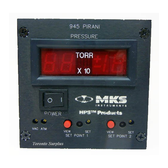
Feature and Control Locations Controller Rear View Front View Side View Digital LED Display Sensor Power On-Off Rocker Switch View Set Point Push-buttons Set Point Adjustment Potentiometers LED Set Point Indicators Atmospheric Adjustment Potentiometer Zero Adjustment Potentiometer Power Cord Inlet w/ Fuse Holder Panel Mounting Fastener Holes Female, 9-pin Gauge Port Male, 9-pin Accessory Port... -
Page 14: Typical Applications For The Series 945 Pirani System
Typical Applications for the Series 945 Pirani System Measuring foreline and roughing pressures generated by mechanical vacuum pumps Controlling valves and pumps to automate system pump down using the relay set points Sensing abnormal pressure and taking appropriate security measures using the relay set points Controlling system pressure using the analog output as input to an automatic pressure controller Starting or stopping system processes using the relay set... -
Page 15: Sensor System
® About the SensaVac Series 945 Pirani Vacuum Sensor System The Series 945 Pirani System, together with its Sensor and connecting cable, provides accurate and reliable data for processes which need pressure measurement from 10 Torr down to 10 Torr. It is low in cost and easy to use. -
Page 16: Installing The Series 945 Pirani System
Installing the Series 945 Pirani System Pirani Sensor Installation Location Locate the Pirani Sensor where it can measure chamber or manifold pressure. Install it away from pumps and gas sources and where vibration is minimal to give the most representative values. Orientation Since a Pirani Sensor is designed to minimize convection, operating position does not affect accuracy. -
Page 17: Pirani Controller Installation
Ensure a solid electrical connection between the Sensor and the grounded vacuum system to shield the tube element from external electromagnetic sources. In applications which the System will be exposed to large voltage fluctuations, install a centering ring with a screen, and then ground the screen and tubing. -
Page 18: Connecting The Sensor To The Controller
Connecting the Sensor to the Controller A sensor cable with a standard octal socket (see Accessories, p. 24) is required for operation but is purchased separately from the Pirani System. This socket has an integrated polarizing tab. The socket has sufficient contact pressure so that strain relief is unnecessary in most applications, but when exerting excessive stress on the cable, use separate strain relief to prevent damage to the Sensor or Controller. -
Page 19: Fuse Replacement
Fuse Replacement The Series 945 Pirani System has a combined fuse holder and power outlet located on the rear panel of the Controller. Replace the fuse with the following steps. 1. Unplug the power cord from its outlet. 2. Snap out the fuse holder drawer. 3. -
Page 20: Relay Inductive Loads And Arc Suppression
Description Set point relay 1 - normally closed contact Set point relay 1 - normally open contact Set point relay 2 - common Not used Analog output voltage (+) Set point relay 1 - common Set point relay 2 - normally closed contact Set point relay 2 - normally open contact Analog output voltage (-) 9-pin Accessory port... -
Page 21: Operating The Series 945 Pirani System
Operating the Series 945 Pirani System Reading Pressure The Sensor must be connected to the Controller before turning on the unit . Turn the power on to display pressure or to operate the set point relays. The table below shows the Series 945 Pirani System’s voltage output as a function of pressure for nitrogen, argon, and helium, and the graph on the next page gives the same information. -
Page 22: Sensor Adjustment
When using the graph, remember that the pressure scale is logarithmic, and the voltage scale is linear. Equal increments of distance along the pressure scale do not correspond to equal pressure changes. Sensor Adjustment ® Series 945 Pirani Controllers and their Sensors are calibrated at HPS However, instances in which user-calibration will be required are: After installation on your system, the Controller and Sensor may need to be calibrated as a unit. -
Page 23: Calibrating For Zero And Atmosphere
Calibrating for Zero and Atmosphere Vacuum and atmosphere adjustment potentiometers are located on the front panel as shown below. The two adjustments can be made independently, but because of some interaction between them, we recommend making the adjustments in the order below. For best results, let the Series 945 Pirani System remain at the calibration pressure for at least 15 minutes before adjusting the potentiometers. -
Page 24: Buffered Analog Output
To avoid damage to the Sensor, vent the vacuum system to atmosphere before removing it. Buffered Analog Output The Series 945 Pirani Controller's analog output voltage is buffered. The temperature compensated signal from the Sensor is buffered by a unity gain amplifier, then connected to the Accessory port. - Page 25 Minimize the chamber volume to reduce the search area and increase the efficiency of the test. Sensitivity to gas leaks is also pressure dependent due to the complex nature of heat transfer at pressures above 10 Torr and the presence of significant radiation and end losses below 10 Torr.
-
Page 26: Using The Series 945 Pirani System With Other Gases
Using the Series 945 Pirani System with Other Gases Before using the Series 945 Pirani System to measure pressure of gases other than air or nitrogen, you should read and understand this section. To answer further questions, contact Applications Engineering at HPS Products at 1-303-449-9861 or 1-800-345-1967. -
Page 27: Calibrating For Other Gases
The nitrogen equivalent pressures of some gases can exceed the measuring capabilities of the Series 945 Pirani Controller. For example, a true pressure of 6.0 Torr of helium is equivalent to a nitrogen equivalent pressure of several 1000 Torr. The Series 945 Pirani Controller is not capable of measuring this pressure of helium. -
Page 28: Maintaining The Series 945 Pirani System
Maintaining the Series 945 Pirani System Troubleshooting and Service The Series 945 Pirani Controller is designed to be maintenance-free under normal operation. If a problem should occur, the following chart lists symptoms, possible causes, and their remedies. With this guide, you should be able to diagnose some problems and correct them. -
Page 29: Cleaning The Pirani Sensor
Cleaning the Pirani Sensor Roughing pump oils and other fluids condensing or decomposing on the heated filament can contaminate the Sensor. This changes the emissivity of the filament, which in turn can cause the calibration to change, especially at low pressure. It is not advisable to clean the Sensor. -
Page 30: Accessories
Accessories Part # Accessory Connector, 9-pin 100004031 Accessory Connector Shell, 9-pin 100005777 Cables for the Pirani Sensor 10 ft ( 3.0 m) 103150006 25 ft ( 7.6 m) 103150007 50 ft (15.2 m) 103150008 100 ft (30.5 m) 103150017 Custom Lengths to 500 ft 103150009 Mounting Hardware Kit 100005021... -
Page 31: Product Warranty
III. This warranty gives PURCHASER specific legal rights, and PURCHASER may also have other rights which vary from state to state. IV. For HPS ® products sold outside of the U.S., contact your MKS representative for warranty information and service. Warranty Performance ®... -
Page 32: Notes
Notes Digital Pirani vacuum Sensor System... -
Page 33: Appendix A: How The Series 945 Pirani System Works
Appendix A: How the Series 945 Pirani System Works The Series 945 Pirani System is a heat-loss manometer which infers the pressure of a gas by measuring thermal loss from a heated wire. Theory of a Thermal Conductivity Sensor A hot wire suspended from supports in a partial vacuum loses thermal energy in three ways: gas transport, which is pressure dependent, end loss to the supports, and... -
Page 34: The Series 945 Pirani System Design Overview
The Series 945 Pirani System Design Overview This section is intended to give the reader an overview of the internal workings of the Series 945 Pirani System. This manual does not provide sufficient detail for advanced levels of troubleshooting. Refer to the block diagram while reading this section. -
Page 35: Notes
Notes Digital Pairani Vacuum Sensor System... - Page 36 Digital Pairani Vacuum Sensor System...
Need help?
Do you have a question about the HPS 945 Series and is the answer not in the manual?
Questions and answers