Advertisement
Table of Contents
- 1 Table of Contents
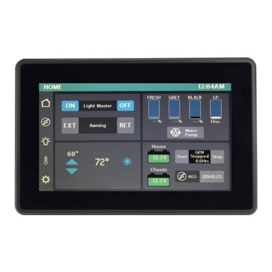
- 2 Lyra Screen Overview
- 3 Home
- 4 Lights
- 5 Auto Gen Start (AGS)
- 6 Climate Control
- 7 Settings
- 8 Settings/Mobile App
- 9 Vegatouch Mira Setup
- 10 Wireless Switch Pairing
- 11 Settings/Network Diagnostics
- 12 Settings/Manufacturer Options
- 13 G8 DC Panel
- 14 Networking
- 15 Network Status Indicators
- 16 Mira NET LED Status Key
- Download this manual
Advertisement
Table of Contents


Need help?
Do you have a question about the Galleria and is the answer not in the manual?
Questions and answers
air conditioner is not cycling off at temp setting and continuing to blow cold air nonstop. how do I troubleshoot this.
To troubleshoot a Firefly Galleria air conditioner that is not cycling off and continues to blow cold air:
1. Check the set temperature: Tap the arrows to adjust the desired temperature (Set Temp). The A/C will run until the current temperature reaches the set temperature, then shut off.
2. Confirm the mode: Make sure the system is in "Cool" mode. If only the fan is running (Fan Only mode), the A/C may not shut off as expected.
3. Fan settings: If using the ProAir option, ensure that Auto mode is selected so the system can control the fan speed. Manual fan speed settings may cause continuous operation.
4. Verify system response: If the air conditioner continues to run despite reaching the set temperature, there may be a system malfunction requiring further diagnostics.
If the issue persists, consult the Diagnostic Tools screen to check connected devices or seek technical support.
This answer is automatically generated