
Summary of Contents for M. J. MAILLIS GROUP SIAT SK20
- Page 1 Semi-automatic sealer SK20 Operation and maintenance manual Translation of the “ORIGINAL INSTRUCTIONS” SBC0030693 Code ed. 09-2017 - rev. 2...
- Page 2 No part of this publication may be reproduced without the written consent of the Manufacturer. Pursuing a policy of continuous improvement, the Manufacturer reserves the right to change this document without notice, provided that such changes do not create risks to safety.
-
Page 3: Table Of Contents
Summary Safety information Purpose of the manual ........................3 Glossary of the terms ........................4 Attached documentation ........................5 General safety warnings ........................5 Safety Warnings for Handling and Installation ................. 6 Safety Warnings for Operation and Use................... 7 Safety Manager Obligations ......................7 Safety Warnings on Misuse...................... - Page 4 Cutting blade cleaning ........................53 Adhesive tape parameter check ..................... 54 Flap length adjustment ........................55 Upper sealing unit (flap 70 mm) ....................55 Lower sealing unit (flap 70 mm) ....................55 Upper sealing unit (flap 50 mm) ....................56 Lower sealing unit (flap 50 mm) ....................
-
Page 5: Safety Information
Safety information Purpose of the manual – The purpose of the manual is to inform and train operators so that they can interact with the machine in SAFE CONDITIONS. – Its aim is also to prevent risks, to reduce the social costs resulting from accidents and damage to the health of people, property and to the environment. -
Page 6: Glossary Of The Terms
Safety information Glossary of the terms The glossary includes some terms used when processing information, with their definition, in order to facilitate understanding. – Training: A process aiming at transferring the knowledge, skills and behaviours re- quired to work in an autonomous, correct and hazard-free manner. –... -
Page 7: Attached Documentation
Safety information Attached documentation The SAFETY WARNINGS and the INSTALLATION MANUAL are supplied as hard- copy publications. – The USE AND MAINTENANCE MANUAL, operation diagrams and all other post-sale documents can be downloaded from the INTERNET. – The list shows the documentation supplied with the machine. –... -
Page 8: Safety Warnings For Handling And Installation
Safety information Safety Warnings for Handling and Installation – The manufacturer has attached special attention to the packaging of the machine, to minimise the risks associated with the shipping, handling and transport phases. – The personnel authorised to handle the machine (loading and unloading) must have acknowledged technical skills and professional ability. -
Page 9: Safety Warnings For Operation And Use
Safety information Safety Warnings for Operation and Use – The machine must be used by one single operator ONLY, who must be trained and capable of performing the work and be in suitable conditions. – Certain steps might request one or more operators, who must be previously trained and informed on the tasks they will have to perform. -
Page 10: Safety Warnings On Misuse
Safety information Safety Warnings on Misuse Improper use: reasonably foreseeable use different from what is specified in the use manual, that may be caused by human behaviour. – ONLY trained, documented and authorized Operators are allowed to use the machine. –... -
Page 11: Safety Warnings For Maintenance And Adjustments
Safety information Safety Warnings for Maintenance and Adjustments – Always keep the machine in optimum operating condition and carry out the routine maintenance according to the intervals and procedures specified by the Manufacturer. – A good maintenance will ensure a stable performance over time, longer working life and constant compliance with the safety requirements. -
Page 12: Safety Warnings For The Electrical Equipment
Safety information Safety warnings for the electrical equipment The electrical equipment has been built in accordance with the applicable stand- ards and its efficiency is ensured if the listed conditions are met. – Ambient temperature and relative humidity between maximum and minimum permitted limits. -
Page 13: Safety And Information Symbols
Safety information - Avoid dumping polluting materials and products in the environment (oils, greases, electrical and electronic apparatus etc.). - All the components of Electrical and Electronic Apparatus contain dangerous sub- stances and are appropriately marked. - Dispose of Electrical and Electronic Apparatus Waste properly, at authorised collec- tion centres, to avoid harmful and damaging effects. - Page 14 Safety information – Cutting hazard: danger sign warning not to come close to the cutting parts with the upper limbs. – Risk of entanglement: danger sign warning not to come close to the moving parts with the upper limbs. – Information Signal: indicates the required direction of rotation for operation.
-
Page 15: Technical Specifications
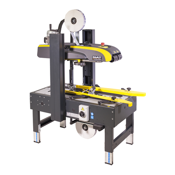
Technical Specifications general description of the machine The SK20 semi-automatic sealer is a machine that uses adhesive tape to seal the top and bottom flaps of cardboard boxes or cases. – The machine is used also to seal small batches of cases that have the same dimen- sions with adhesive tape. -
Page 16: Description Of The Main Components
Technical Specifications Description of the main components The image shows the main components and the list reports their description and function. English language Operation and maintenance manual... - Page 17 Technical Specifications A) Work top: it is equipped with conveyor belts B that enable case transfer. B) Lower conveyor: it moves cases during the sealing operation. – Unit is equipped with belts operated by a gear-motor. C) Upper conveyor: it moves cases during the sealing operation. –...
-
Page 18: Manufacturer And Machine Identification
Technical Specifications Manufacturer and machine identification The identification plate (pictured) is affixed directly to the machine. – In addition to the references for iden- tification provided by the Manufac- turer, they also list all the essential information for a safe operation. A) Manufacturer identification B) Space reserved for CE compliance marking... -
Page 19: Description Of The Safety Devices
Technical Specifications Description of the safety devices The machine is equipped with safety devices that reduce the risks during the man-machine interaction. A) Electric disconnector: safety con- trol that powers the electric panel. B) Emergency stop button: safety control that, in case of an imminent risk, stops all parts whose function might constitute a risk. -
Page 20: Specifications
Technical Specifications Specifications Table: Technical data of the machine Description Unit of measurement Value Electric supply see the identification plate Machine dimensions Dimensions (LxW) 1080 x 740 Height H (standard legs) 1280 ÷ 1830 Height H1 (standard legs + set of wheels AS77) 1390 ÷... -
Page 21: Description Of Outer Areas
Technical Specifications Description of outer areas The figure shows different areas to be considered in the planning of the installation area. A) Operator control and standing area B) Case feed area C) Case transfer area to next steps D) Perimeter area Operation and maintenance manual English language... -
Page 22: Position Of Information And Safety Plates
Technical Specifications Position of information and safety plates The figure shows the position of the signals applied on the machine. – Please keep safety signs and infor- mation legible and follow the instruc- tions. – Signals which are no longer legible must be replaced and repositioned in the same place of origin. -
Page 23: Use And Functioning
Use and functioning Recommendations on Operation and Use – The machine must be used by one single operator ONLY, who must be trained and capable of performing the work and be in suitable conditions. – Consult the user manual, in particular during the first use, and make sure that you fully understand its content. -
Page 24: Control Description
Use and functioning Control description The illustration shows the main commands and their description and function are listed. A) Electric disconnector: safety con- trol that powers the electric panel. – “OFF” position: function deactivated. – Position “TRIPPED”: stop in emer- gency conditions. -
Page 25: Start And Stop
Use and functioning Start and stop The figure shows the points of intervention and the description shows the proce- dures to be adopted. Start-up ▀ 1. Make sure that the machine has been adjusted to the dimensions of the cases to be sealed. 2. -
Page 26: Emergency Stop And New Start-Up
Use and functioning Emergency stop and new start-up The figure shows the points of intervention and the description shows the proce- dures to be adopted. 1. In the presence of an imminent risk press the emergency stop button B. – All moving devices immediately stop. –... -
Page 27: Maintenance
Maintenance Recommendations for maintenance interventions – The recommendations represent a summary of those shown in the SAFETY WARN- INGS section. – The personnel authorized to carry out the ordinary maintenance must have qualified expertise and specific skills in the field of intervention. –... -
Page 28: Scheduled Maintenance Intervals
Maintenance Scheduled maintenance intervals Always keep the machine in optimum operating condition and carry out the routine maintenance according to the intervals and procedures specified by the Manufac- turer. – In case of prolonged inactivity, carry out some maintenance operations in order to preserve functionality and prevent further damages. -
Page 29: Diagram Of The Points Of Lubrication
Maintenance Diagram of the points of lubrication Lubricate the parts indicated according to the frequency and methods shown. – Use the lubricants (oils and greases) recommended by the Manufacturer or lubricants of equivalent chemical and physical characteristics. – Some components (reducers, bear- ings, etc.) do not request lubrication because they are self-lubricating or life lubricated. -
Page 30: Lubricant Table
Maintenance Lubricant table Use the lubricants (oils and greases) recommended by the Manufacturer or lubri- cants of equivalent chemical and physical characteristics. Table: Recommended lubricants Lubricant type make Abbreviation Component Synthetic grease Tecnolube Seal Rheolube 393 - Upper conveyor adjusting screw - Cutting blade Standard lubricating oil - Sealing unit rollers... -
Page 31: Size Change Adjustments
Maintenance Size change adjustments The operations described are required to prepare the machine for sealing a batch of identical cases. – The figure shows the points of intervention and the description shows the procedures to be adopted. – The operations must be carried out with with the machine stopped and in safe conditions. - Page 32 Maintenance 13. Tighten the knobs B. 14. Move the case along the path to check that it slides with moderate pressure. Case must be conveyed with mini- mum speed without getting stuck along the way. 15. Remove case When production starts, make sure that the operation has been properly performed in order to avoid exces- sive waste.
-
Page 33: Lower Conveyor Belt Adjustment
Maintenance Lower conveyor belt adjustment The operation must be carried out by the maintenance technician or by personnel with suitable competences, skills and knowledge. Make sure to fulfil the required requirements in order to work under safe condi- tions. – The figure shows the points of intervention and the description shows the procedures to be adopted. -
Page 34: Upper Conveyor Belt Adjustment
Maintenance Upper conveyor belt adjustment The operation must be carried out by the maintenance technician or by personnel with suitable competences, skills and knowledge. Make sure to fulfil the required requirements in order to work under safe condi- tions. – The figure shows the points of intervention and the description shows the procedures to be adopted. - Page 35 Maintenance 16. Fit the pressure roller E without securing it with the fasteners D. 17. Repeat the operation on the other equal component. 18. Adjust the position of the pressure rollers and secure them with the fasteners D. 19. Start the machine and make sure that the operation has been carried out properly. –...
-
Page 36: Lower Conveyor Belt Replacement
Maintenance Lower conveyor belt replacement The operation must be carried out by the maintenance technician or by personnel with suitable competences, skills and knowledge. Make sure to fulfil the required requirements in order to work under safe condi- tions. – The figure shows the points of intervention and the description shows the procedures to be adopted. - Page 37 Maintenance Important Do not overtighten so as not to cause any malfunctioning. 16. Tighten the nut G. 17. Repeat the operations on other belt. Adjust the belts to the same tension. 18. Reassemble the guard F. 19. Introduce and tighten the screws E. 20.
-
Page 38: Replacement Of Upper Conveyor Belts
Maintenance Replacement of upper conveyor belts The operation must be carried out by the maintenance technician or by personnel with suitable competences, skills and knowledge. Make sure to fulfil the required requirements in order to work under safe condi- tions. –... - Page 39 Maintenance 14. Slide worn belt manually until coupling P reaches an easily accessible point. 15. Disconnect the ends of belts. 16. Connect the ends of new belt and insert pin P in order to carry out coupling. 17. Adjust the tension of belt by means of the adjusting system N. Important Do not overtighten so as not to cause any malfunctioning.
-
Page 40: Replacing The Set Of 600 Mm High Legs (As80)
Maintenance Replacing the Set of 600 mm high legs (AS80) The operation must be carried out by the maintenance technician or by personnel with suitable competences, skills and knowledge. Make sure to fulfil the required requirements in order to work under safe condi- tions. - Page 41 Maintenance 11. Check that the machine is level (longitudinally and transversally). To ensure that it is levelled properly, use the screws B to adjust the height of the feet that are not correct. 12. Plug the connector into the electrical power outlet. –...
-
Page 42: Fitting The Set Of Wheels For Feet (As77)
Maintenance Fitting the set of wheels for feet (AS77) The operation must be carried out by the maintenance technician or by personnel with suitable competences, skills and knowledge. Make sure to fulfil the required requirements in order to work under safe condi- tions. - Page 43 Maintenance 11. Put the machine on the floor. 12. Position the machine in its chosen setting. 13. Check that the machine is level (longitudinally and transversally). To ensure that it is levelled properly, use the screws to adjust the height of the feet that are not correct.
-
Page 44: Fitting The Set Of 200 Mm High Column Extensions
Maintenance Fitting the set of 200 mm high column extensions The operation must be carried out by the maintenance technician or by personnel with suitable competences, skills and knowledge. Make sure to fulfil the required requirements in order to work under safe condi- tions. - Page 45 Maintenance 11. Loosen the screws L. 12. Remove the plate M. 13. Insert the spacers N. 14. Insert the extension P. 15. Refit the plate M and secure it with the screws L. 16. Use the crank handle C to lift the head B.
-
Page 46: Disassembly And Assembly Of Upper Sealing Unit
Maintenance Disassembly and assembly of upper sealing unit The operation is necessary to carry out adjustment and maintenance operations. – The figure shows the points of intervention and the description shows the procedures to be adopted. 1. Mark the intervention area and pre- vent access to the devices that, if ac- tivated, may cause unexpected haz- ards and jeopardize the safety level. -
Page 47: Disassembly And Assembly Of Lower Sealing Unit
Maintenance Disassembly and assembly of lower sealing unit The operation is necessary to carry out adjustment and maintenance operations. The figure shows the points of intervention and the description shows the proce- dures to be adopted. 1. Mark the intervention area and pre- vent access to the devices that, if ac- tivated, may cause unexpected haz- ards and jeopardize the safety level. -
Page 48: Machine Disposal And Scrapping
Maintenance Machine Disposal and Scrapping Machine dismantling ▀ – Disconnect the supplies form the energy sources (electrical, pneumatic, etc.) in order to prevent any restart. – Carefully drain the systems containing hazardous substances, according to the appli- cable regulations on safety at work and environmental protection. –... -
Page 49: K11 Sealing Unit
K11 sealing unit Description of sealing unit Sealing unit is fitted with an adhesive tape holder that seals the lower and upper part of the cardboard cases and/or cartons. – The K11 version is specifically for 2” adhesive tape. – Each sealing unit is equipped with devices that apply and cut the adhesive tape. –... - Page 50 K11 sealing unit M) Case outlet roller N) Adhesive tape roller smoothing brush P) Roller return spring – Tape stretcher is supplied; it is necessary to guide the adhesive tape for the first time. English language Operation and maintenance manual...
-
Page 51: Sealing Unit Technical Specifications
K11 sealing unit Sealing unit technical specifications Table: Sealing unit technical specifications K11 Description Unit of measurement Sealing unit size Length, width, height (LxWxH) 400 x 98 x 480 Weight 5,75 Dimensions of adhesive tape roller Flap length (A) 70-50-30 ¹) Inside Diameter (d) mm (inch) 76 (3”) -
Page 52: Supplying And Guiding Adhesive Tape
K11 sealing unit Supplying and guiding adhesive tape The intervention must be carried out with the machine stopped in safety condi- tions. Attention Warning Wear the suitable personal protective equipment (gloves) to avoid any cutting haz- ard. Lower sealing unit ▀... - Page 53 K11 sealing unit Upper sealing unit ▀ 10. Remove the adhesive tape from the sealing unit. 11. Remove the cardboard core. 12. Insert new roller. 13. Apply tape stretcher B to the adhe- sive side of the tape. 14. Guide tape stretcher until the tape stretcher is beyond the point of tan- gency of case inlet roller.
- Page 54 K11 sealing unit – The figure shows the path of the adhesive tape according to the length of flap. English language Operation and maintenance manual...
-
Page 55: Cutting Blade Cleaning
K11 sealing unit Cutting blade cleaning The figure shows the points of intervention and the description shows the proce- dures to be adopted. – The intervention must be carried out with the machine stopped in safety conditions. Attention Warning Wear the suitable personal protective equipment (gloves) to avoid any cut- ting hazard. -
Page 56: Adhesive Tape Parameter Check
K11 sealing unit Adhesive tape parameter check The figure shows the points of intervention and the description shows the proce- dures to be adopted. – This check is necessary to make sure that the adhesive tape is prop- erly applied to the cases. Adhesive tape centring... -
Page 57: Flap Length Adjustment
K11 sealing unit Flap length adjustment This action is necessary to adjust the length of the adhesive tape flap. The lower and upper flap can be set with different lengths according to the produc- tion requirements. – The intervention must be carried out with the machine stopped in safety condi- tions. -
Page 58: Upper Sealing Unit (Flap 50 Mm)
K11 sealing unit Upper sealing unit (flap 50 mm) ▀ 1. Remove the adhesive tape from the sealing unit. 2. Components A-C must be installed as shown in the figure. 3. Apply tape stretcher to the adhesive side of the tape. 4. -
Page 59: Upper Sealing Unit (Flap 30 Mm)
K11 sealing unit Upper sealing unit (flap 30 mm) ▀ 1. Remove the adhesive tape from the sealing unit. 2. Components A-C-F must be installed as shown in the figure. 3. Apply tape stretcher to the adhesive side of the tape. 4. -
Page 60: Replacement Of The Cutting Blade
K11 sealing unit Replacement of the cutting blade The figure shows the points of intervention and the description shows the proce- dures to be adopted. – The intervention must be carried out with the machine stopped in safety conditions. Attention Warning Wear the suitable personal protective equipment (gloves) to avoid any cut-... -
Page 61: K11-R Sealing Unit
K11-R sealing unit Description of sealing unit Sealing unit is fitted with an adhesive tape holder that seals the lower and upper part of the cardboard cases and/or cartons. The K11 R version is specifically for 2” adhesive tape. The versions are suitable for use with cut-resistant adhesive tape. –... - Page 62 K11-R sealing unit H) Cutting blade L) Cutting blade protection M) Cut adjustment sliding block N) Case outlet roller P) Adhesive tape roller smoothing brush Q) Roller return spring – Tape stretcher is supplied; it is necessary to guide the adhesive tape for the first time.
-
Page 63: Sealing Unit Technical Specifications
K11-R sealing unit Sealing unit technical specifications Table: Sealing unit technical specifications K11 R Description Unit of measurement K11 R Sealing unit size Length, width, height (LxWxH) 400 x 98 x 480 Weight 5,93 Dimensions of adhesive tape roller Flap length (A) 70-50-30 ¹) Inside Diameter (d) mm (inch) -
Page 64: Supplying And Guiding Adhesive Tape
K11-R sealing unit Supplying and guiding adhesive tape The intervention must be carried out with the machine stopped in safety condi- tions. Attention Warning Wear the suitable personal protective equipment (gloves) to avoid any cutting haz- ard. Lower sealing unit ▀... - Page 65 K11-R sealing unit Upper sealing unit ▀ 10. Remove the adhesive tape from the sealing unit. 11. Remove the cardboard core. 12. Insert new roller. 13. Apply tape stretcher B to the adhe- sive side of the tape. 14. Guide tape stretcher until the tape stretcher is beyond the point of tan- gency of case inlet roller.
- Page 66 K11-R sealing unit – The figure shows the path of the adhesive tape according to the length of flap. English language Operation and maintenance manual...
-
Page 67: Cutting Blade Cleaning
K11-R sealing unit Cutting blade cleaning The figure shows the points of intervention and the description shows the proce- dures to be adopted. – The intervention must be carried out with the machine stopped in safety conditions. Attention Warning Wear the suitable personal protective equipment (gloves) to avoid any cut- ting hazard. -
Page 68: Adhesive Tape Parameter Check
K11-R sealing unit Adhesive tape parameter check The figure shows the points of intervention and the description shows the proce- dures to be adopted. – This check is necessary to make sure that the adhesive tape is prop- erly applied to the cases. Adhesive tape centring... -
Page 69: Flap Length Adjustment
K11-R sealing unit Flap length adjustment This action is necessary to adjust the length of the adhesive tape flap. The lower and upper flap can be set with different lengths according to the produc- tion requirements. – The intervention must be carried out with the machine stopped in safety condi- tions. -
Page 70: Upper Sealing Unit (Flap 50 Mm)
K11-R sealing unit Upper sealing unit (flap 50 mm) ▀ 1. Remove the adhesive tape from the sealing unit. 2. Components A-C must be installed as shown in the figure. 3. Apply tape stretcher to the adhesive side of the tape. 4. -
Page 71: Upper Sealing Unit (Flap 30 Mm)
K11-R sealing unit Upper sealing unit (flap 30 mm) ▀ 1. Remove the adhesive tape from the sealing unit. 2. Components A-C-F must be installed as shown in the figure. 3. Apply tape stretcher to the adhesive side of the tape. 4. -
Page 72: Replacement Of The Cutting Blade
K11-R sealing unit Replacement of the cutting blade The figure shows the points of intervention and the description shows the proce- dures to be adopted. – The intervention must be carried out with the machine stopped in safety conditions. Attention Warning Wear the suitable personal protective equipment (gloves) to avoid any cut-... -
Page 73: K12 Sealing Unit
K12 sealing unit Description of sealing unit Sealing unit is fitted with an adhesive tape holder that seals the lower and upper part of the cardboard cases and/or cartons. – The K12 version is specifically for 3” adhesive tape. – Each sealing unit is equipped with devices that apply and cut the adhesive tape. –... - Page 74 K12 sealing unit M) Case outlet roller N) Adhesive tape roller smoothing brush P) Roller return spring – Tape stretcher is supplied; it is necessary to guide the adhesive tape for the first time. English language Operation and maintenance manual...
-
Page 75: Sealing Unit Technical Specifications
K12 sealing unit Sealing unit technical specifications Table: Sealing unit technical specifications K12 Description Unit of measurement Sealing unit size Length, width, height (LxWxH) 400 x 123 x 480 Weight 6,25 Dimensions of adhesive tape roller Flap length (A) 70-50-30 ¹) Inside Diameter (d) mm (inch) 76 (3”) -
Page 76: Supplying And Guiding Adhesive Tape
K12 sealing unit Supplying and guiding adhesive tape The intervention must be carried out with the machine stopped in safety condi- tions. Attention Warning Wear the suitable personal protective equipment (gloves) to avoid any cutting haz- ard. Lower sealing unit ▀... - Page 77 K12 sealing unit Upper sealing unit ▀ 10. Remove the adhesive tape from the sealing unit. 11. Remove the cardboard core. 12. Insert new roller. 13. Apply tape stretcher B to the adhe- sive side of the tape. 14. Guide tape stretcher until the tape stretcher is beyond the point of tan- gency of case inlet roller.
- Page 78 K12 sealing unit – The figure shows the path of the adhesive tape according to the length of flap. English language Operation and maintenance manual...
-
Page 79: Cutting Blade Cleaning
K12 sealing unit Cutting blade cleaning The figure shows the points of intervention and the description shows the proce- dures to be adopted. – The intervention must be carried out with the machine stopped in safety conditions. Attention Warning Wear the suitable personal protective equipment (gloves) to avoid any cut- ting hazard. -
Page 80: Adhesive Tape Parameter Check
K12 sealing unit Adhesive tape parameter check The figure shows the points of intervention and the description shows the proce- dures to be adopted. – This check is necessary to make sure that the adhesive tape is prop- erly applied to the cases. Adhesive tape centring... -
Page 81: Flap Length Adjustment
K12 sealing unit Flap length adjustment This action is necessary to adjust the length of the adhesive tape flap. The lower and upper flap can be set with different lengths according to the produc- tion requirements. – The intervention must be carried out with the machine stopped in safety condi- tions. -
Page 82: Upper Sealing Unit (Flap 50 Mm)
K12 sealing unit Upper sealing unit (flap 50 mm) ▀ 1. Remove the adhesive tape from the sealing unit. 2. Components A-C must be installed as shown in the figure. 3. Apply tape stretcher to the adhesive side of the tape. 4. -
Page 83: Upper Sealing Unit (Flap 30 Mm)
K12 sealing unit Upper sealing unit (flap 30 mm) ▀ 1. Remove the adhesive tape from the sealing unit. 2. Components A-C-F must be installed as shown in the figure. 3. Apply tape stretcher to the adhesive side of the tape. 4. -
Page 84: Replacement Of The Cutting Blade
K12 sealing unit Replacement of the cutting blade The figure shows the points of intervention and the description shows the proce- dures to be adopted. – The intervention must be carried out with the machine stopped in safety conditions. Attention Warning Wear the suitable personal protective equipment (gloves) to avoid any cut-... -
Page 85: K12-R Sealing Unit
K12-R sealing unit Description of sealing unit Sealing unit is fitted with an adhesive tape holder that seals the lower and upper part of the cardboard cases and/or cartons. The K12 R version is specifically for 3” adhesive tape. The versions are suitable for use with cut-resistant adhesive tape. –... - Page 86 K12-R sealing unit H) Cutting blade L) Cutting blade protection M) Cut adjustment sliding block N) Case outlet roller P) Adhesive tape roller smoothing brush Q) Roller return spring – Tape stretcher is supplied; it is necessary to guide the adhesive tape for the first time.
-
Page 87: Sealing Unit Technical Specifications
K12-R sealing unit Sealing unit technical specifications Table: Sealing unit technical specifications K12 R Description Unit of measurement K12 R Sealing unit size Length, width, height (LxWxH) 400 x 123 x 480 Weight 6,44 Dimensions of adhesive tape roller Flap length (A) 70-50-30 ¹) Inside Diameter (d) mm (inch) -
Page 88: Supplying And Guiding Adhesive Tape
K12-R sealing unit Supplying and guiding adhesive tape The intervention must be carried out with the machine stopped in safety condi- tions. Attention Warning Wear the suitable personal protective equipment (gloves) to avoid any cutting haz- ard. Lower sealing unit ▀... - Page 89 K12-R sealing unit Upper sealing unit ▀ 10. Remove the adhesive tape from the sealing unit. 11. Remove the cardboard core. 12. Insert new roller. 13. Apply tape stretcher B to the adhe- sive side of the tape. 14. Guide tape stretcher until the tape stretcher is beyond the point of tan- gency of case inlet roller.
- Page 90 K12-R sealing unit – The figure shows the path of the adhesive tape according to the length of flap. English language Operation and maintenance manual...
-
Page 91: Cutting Blade Cleaning
K12-R sealing unit Cutting blade cleaning The figure shows the points of intervention and the description shows the proce- dures to be adopted. – The intervention must be carried out with the machine stopped in safety conditions. Attention Warning Wear the suitable personal protective equipment (gloves) to avoid any cut- ting hazard. -
Page 92: Adhesive Tape Parameter Check
K12-R sealing unit Adhesive tape parameter check The figure shows the points of intervention and the description shows the proce- dures to be adopted. – This check is necessary to make sure that the adhesive tape is properly applied to the cases. Adhesive tape centring... -
Page 93: Flap Length Adjustment
K12-R sealing unit Flap length adjustment This action is necessary to adjust the length of the adhesive tape flap. The lower and upper flap can be set with different lengths according to the produc- tion requirements. – The intervention must be carried out with the machine stopped in safety condi- tions. -
Page 94: Upper Sealing Unit (Flap 50 Mm)
K12-R sealing unit Upper sealing unit (flap 50 mm) ▀ 1. Remove the adhesive tape from the sealing unit. 2. Components A-C must be installed as shown in the figure. 3. Apply tape stretcher to the adhesive side of the tape. 4. -
Page 95: Upper Sealing Unit (Flap 30 Mm)
K12-R sealing unit Upper sealing unit (flap 30 mm) ▀ 1. Remove the adhesive tape from the sealing unit. 2. Components A-C-F must be installed as shown in the figure. 3. Apply tape stretcher to the adhesive side of the tape. 4. -
Page 96: Replacement Of The Cutting Blade
K12-R sealing unit Replacement of the cutting blade The figure shows the points of intervention and the description shows the proce- dures to be adopted. – The intervention must be carried out with the machine stopped in safety conditions. Attention Warning Wear the suitable personal protective equipment (gloves) to avoid any cut-... -
Page 97: Analytical Index
Analytical index - Upper sealing unit (flap 30 mm), 81 - Upper sealing unit (flap 50 mm), 80 – Adhesive tape parameter check (K11-R sealing unit), 66 - Upper sealing unit (flap 70 mm), 79 – Adhesive tape parameter check (K11 sealing unit), 54 –... - Page 98 – Supplying and guiding adhesive tape (K11-R sealing unit), – Supplying and guiding adhesive tape (K11 sealing unit), 50 – Supplying and guiding adhesive tape (K12-R sealing unit), – Supplying and guiding adhesive tape (K12 sealing unit), 74 – Upper conveyor belt adjustment, 32 English language Operation and maintenance manual...
Need help?
Do you have a question about the SIAT SK20 and is the answer not in the manual?
Questions and answers