
Related Manuals for THOMSON Grass Valley Newton

Summary of Contents for THOMSON Grass Valley Newton
- Page 1 Newton MODULAR CONTROL SYSTEM Instruction Manual SOFTWARE VERSION 1.0 071823401 JULY 2003...
- Page 2 +33 1 45 29 73 00 Germany +49 221 1791 234 +49 221 1791 235 Copyright © Thomson Broadcast and Media Solutions All rights reserved. Grass Valley Web Site www.thomsongrassvalley.com web site offers the following: — Current versions of product catalogs, brochures,...
-
Page 3: Preface
Preface About This Manual This manual provides installation, configuration, operation, and safety and regulatory information for the Newton Modular Control system rack mount and software control panels for controlling Gecko 8900 Series and Kameleon 2000 Series modular products. Newton Instruction Manual... - Page 4 Preface Newton Instruction Manual...
-
Page 5: Table Of Contents
Contents Preface ..............About This Manual . - Page 6 Contents Section 3 — Configuration ..........Network and Operating Parameter Configuration .
-
Page 7: Regulatory Notices
Regulatory Notices Certifications and Compliances FCC Emission Control This equipment has been tested and found to comply with the limits for a Class A digital device, pursuant to Part 15 of the FCC Rules. These limits are designed to provide reasonable protection against harmful interference when the equipment is operated in a commercial environment. -
Page 8: En55103-1/2 Class A Warning
Regulatory Notices EN55103-1/2 Class A Warning For products that comply with Class A. In a domestic environment this product may cause radio interference in which case the user may be required to take adequate measures. This product has been evaluated for Electromagnetic Compatibility under the EN 55103-1/2 standards for Emissions and Immunity and meets the requirements for E4 environment. -
Page 9: Safety Summary
Safety Summary Read and follow the important safety information below, noting especially those instructions related to risk of fire, electric shock or injury to persons. Additional specific warnings not listed here may be found throughout the manual. WARNING Any instructions in this manual that require opening the equipment cover or enclosure are for use by qualified service personnel only. -
Page 10: Symbols On The Product
Safety Summary Symbols on the Product The following symbols may appear on the product: Indicates that dangerous high voltage is present within the equipment enclosure that may be of sufficient magnitude to constitute a risk of electric shock. Indicates that user, operator or service technician should refer to product manual(s) for important operating, maintenance, or service instructions. -
Page 11: Cautions
Safety Summary — Use only the power cord supplied or specified for Use proper power cord this product. Ground product — Connect the grounding conductor of the power cord to earth ground. — Do not operate this Operate only with covers and enclosure panels in place product when covers or enclosure panels are removed. - Page 12 Safety Summary — If you suspect product Do not operate with suspected equipment failure damage or equipment failure, have the equipment inspected by qualified service personnel. — If mains switch is not provided, the power cord(s) Ensure mains disconnect of this equipment provide the means of disconnection. The socket outlet must be installed near the equipment and must be easily accessible.
-
Page 13: Section 1 - Newton Overview
Section Newton Overview Introduction The Newton modular control system provides comprehensive and consol- idated real-time control for Grass Valley modular products. Two control panel designs give fast, multi-knob, Ethernet-based access in a user-config- ured processing channel. A standard Ethernet TCP/IP communications interface and a standard XML data format provide complete signal pro- cessing monitoring and control. -
Page 14: Newton Control Panels
Section 1 — Newton Overview Newton Control Panels The Newton system features two control panels: a rack-mounted version and a software-based PC version. The NewtonPC software panel applica- tion has similar functionality as the rack mount panel, making operation easier to learn. Any combination and number of panels can be used in a net- work;... -
Page 15: Newton Software Control Panel
Newton Control Panels Newton Software Control Panel The Newton software control panel (Figure 2) offers similar functionality to the rack mount control panel in a Windows-based PC software panel application. Any PC on the network running the Newton software panel application can configure and adjust processing channels. -
Page 16: Netconfig Application
Section 1 — Newton Overview NetConfig Application With the NetConfig application installed, in addition to using Newton Panel Configurator to configure the Newton panels, the PC can be used to set IP addresses of panel and modular frame devices on the network and update software to frame controllers and media modules when updates become available. -
Page 17: Newton Panel Configurator Plug-In Tool
NetConfig Application Newton Panel Configurator Plug-In Tool The Newton Panel Configurator for NetConfig (Figure 4) is included. It provides an easy interface for configuring a signal processing path—or channel—that includes an individual module or a string of modules. Next, the adjustable parameters or setups can be defined for each channel. Each setup contains the assignments for the four control knobs. -
Page 18: Using Newton
Section 1 — Newton Overview Using Newton The Newton modular control system lets you quickly access all of the Gecko and Kameleon modules in a signal processing path to make audio, video, and timing adjustments from a single or multiple control points. As an example of utilizing the Newton control system, an ideal real-time application would be quality analysis and control of satellite and micro- wave incoming feeds. - Page 19 Using Newton Figure 5. Newton Control Diagram Newton Software NetConfig with Control Panel Newton Control Extension NetCentral SNMP Monitoring Encore Router Control Ethernet Facility LAN Newton Hardware Control Panel Newton Hardware Control Panel Video Video Audio Master Studio Edit Route Enable Proc Timing...
-
Page 20: Newton System Components And Options
Section 1 — Newton Overview Newton System Components and Options Refer to Table 2 for a summary of the standard system components avail- able with each Newton model and any options that can be purchased. Table 2. Newton System Components and Options Model Name Components Newt-PC... -
Page 21: Section 2 - Installation
Section Installation This section contains the following installation information: • System Requirements • Newt-PC installation for software panel, NetConfig application and Newton Panel Configurator • 1 RU Rack Mount Control Panel Installation, NetConfig application and Newton Panel Configurator Once installation is complete, each rack mount panel must be configured for connection to the facility Ethernet. -
Page 22: Gecko And Kameleon System Requirements
Section 2 — Installation Gecko and Kameleon System Requirements: Operation of the Newton Modular Control System requires the following Rack Mount and software for the Gecko 8900 and Kameleon 2000 Series systems: • 8900NET module with version 3.2.0 software or later Kameleon 2000 series system requirements: •... -
Page 23: Installing Newton Control Panel Application
Newton Control Panel Application Installation Installing Newton Control Panel Application Install the Newt-PC Control Panel software and additional components on a networked PC as follows: 1. Insert the Newt-PC CD-ROM into the CD drive in your networked PC. 2. The setup application should autorun when inserted. If not, locate the Newt-PC1-Setup.EXE file in the Newt-PC folder and double-click on it to start the installation. - Page 24 Section 2 — Installation 4. Read the license agreement (Figure 7) and click on the radio I Agree button, then the button to continue. Next > Pressing the button will halt the install. I Disagree Figure 7. License Agreement Screen 5.
- Page 25 Newton Control Panel Application Installation 6. In the Select Components screen (Figure 9 on page 25), select the Newton and NetConfig checkboxes for every installation. NetConfig is required for Newton panel configuration. Note If you have an older version of NetConfig update to this version for proper Newton configuration capability.
-
Page 26: Shortcuts
Section 2 — Installation The Installing progress screen will be displayed (Figure 11). Figure 11. Installation Progress Screen Once installation is completed and successful, a Finish screen will be dis- played (Figure 12). 9. Press the Finish > button to exit. Figure 12. -
Page 27: Control Panel Settings
Newton Rack Mount Control Panel Installation Control Panel Settings The following monitor settings are recommended for best viewing of the software panel application: • From the Windows Start menu, select Control Panels/Dis- play/Advanced/Small Fonts • Set the screen resolution to 1024 x 768 or higher Newton Rack Mount Control Panel Installation Installation of the Newton 1 RU rack mount control panel is a process of: •... -
Page 28: Installing Newton Rack Mount Control Panel Software
Section 2 — Installation Installing Newton Rack Mount Control Panel Software The Newt-RM (1 RU Rack Mount panel) comes with a CD-ROM with the Newton rack mount panel software along with the NetConfig networking application and the Newton Panel Configurator necessary for configuring panels. - Page 29 Newton Rack Mount Control Panel Installation Figure 13. NetConfig Update Devices Window 3. Highlight the Device Type name of the software version you wish to update. 4. Check the box for the Newton rack mount panel to update in the Client Name list.
-
Page 30: Uninstalling Software
Section 2 — Installation Uninstalling Software To uninstall Newt-PC or NetConfig use the Windows Add/Remove Pro- grams utility. Configuration This completes software installation for both software and rack mount panels. Proceed to Section 3-Configuration for complete details on config- uring and downloading configurations to the Newton panels. Newton Instruction Manual... -
Page 31: Network And Operating Parameter Configuration
Section ConÞguration This section describes configuration of the control panel for: • Networking the panel(s) to the modules in your facility (setting IP Addresses) and adjusting the rack mount panel operating parameters (name, lamp intensity, etc.), and • Defining channels and setups for module control by the panels. Network and Operating Parameter Configuration The first step in using either the rack mount or software panel is net- working the panels to access the frames containing the 8900 and 2000... - Page 32 Section 3 — Configuration Note Software panels are not seen in the tree structure. 5. Locate the Newton rack mount panel you want to configure. New panels will appear with a red indicator dot, showing a default IP Address. 6. Highlight the Newton rack mount panel name. The Newton Panel Description page (Figure 14) will come up and display read-only...
- Page 33 Network and Operating Parameter Configuration Before proceeding to the other links on the page, use NetConfig to set the IP Address for this Newton panel as follows. 1. Select the Set IP Address icon in the Netconfig toolbar to set the IP Address of this panel.
- Page 34 Section 3 — Configuration Select the link on the left of the Newton Panel Description page Panel System to bring up the Newton Panel System Configuration page (Figure 16). The configuration will be the factory default values. Make Figure 16. Newton Panel System Configuration Page 1.
- Page 35 Network and Operating Parameter Configuration This will bring up the Newton Panel Network Configuration page (Figure 17). The current Ethernet IP, Subnet Mask IP and Gateway IP addresses set on page 33 will be displayed. Figure 17. Newton Panel Network Configuration Page You can also use this page to set the IP Addresses of the panel as follows: 1.
- Page 36 Section 3 — Configuration Select the link to view a read-only listing of the factory Factory Default defaults that are set for the Newton panel at the factory and will appear if button is selected on the previous web page (Figure 18).
-
Page 37: Panel Configuration
Panel Configuration Panel Configuration The overall concept of Newton operation is based on Engineering configu- ration of the knobs and soft key buttons on each panel. Once channels and setups are defined, operators can use the navigation buttons and config- urable soft keys to access the parameters. -
Page 38: Configuring Channels And Setups
Section 3 — Configuration Configuring Channels and Setups This section describes how to configure channels and setups for a Newton Control Panel. It is divided into the following sections: • Newton Panel Configurator Overview • Creating a Configuration • Soft Key Functions and Assignments •... - Page 39 Panel Configuration Figure 19. Load Previously Saved Config File The area labeled Current Configuration contains the following controls for creating or editing a configuration: • button – select this button to bring up a window (Figure New Config to enter a name for a new configuration. Enter a First Channel Name and First Setup Name for that configuration.
- Page 40 Section 3 — Configuration Figure 21. Newton Panel Configurator Screen Configure Newton Panels icon Newton Instruction Manual...
- Page 41 Panel Configuration • – select this button to name a new channel in the Enter New Channel Name window (Figure 22). Select when finished to enter the name in the Channel Name list under the button on the main New Channel screen.
- Page 42 Section 3 — Configuration • – select this button to name a new setup once a channel has New Setup been defined above. The Enter Name window is identical to Figure 22 on page 41. Select when finished to enter the name in the Setup Name list under the button on the main screen.
- Page 43 Panel Configuration The Module area shown in Figure 26 displays a selected module and its published parameters available for configuring setups. Any module that appears in the main tree structure on the left can be selected and dragged to this window. Note Not all modules will have configurable parameters.
- Page 44 Section 3 — Configuration The following information about a module is displayed in the window (Figure 26): • – displays the name of the module that has been dragged Module Name and dropped into the parameter window. • – displays the IP Address of the frame containing the Frame IP Address displayed module.
- Page 45 Panel Configuration • Description – a description of the parameter from the module. Informa- tion on what this control does on the module is available in the specific module instruction manual. The order of the information columns for the parameters can be changed by dragging a control to a different location as shown in Figure Figure 27.
- Page 46 Section 3 — Configuration The Newton Panel area at the bottom of the Newton Panel Configurator window shown in Figure 28 allows a configuration to be sent to, or read from, a panel present on the LAN. When a panel is dragged and dropped to the Newton Panel area, the fol- lowing information about the panel is displayed: •...
- Page 47 Panel Configuration Router Configuration Tab This tab in the Newton Panel Configurator (Figure 29) accesses a Router Configuration interface. This functionality is currently not supported. Figure 29. Router Configuration Tab Newton Instruction Manual...
- Page 48 Section 3 — Configuration Soft Key Configuration Tab The Soft Key Configuration tab (Figure 30) provides a method to assign soft keys to channels and setups. This process can also be performed locally at the panel. Refer to Soft Key Functions and Assignments on page 56 for a more detailed explanation.
-
Page 49: Creating A Configuration
Panel Configuration Other Tab The Other tab (Figure 31) provides information on software for the Newton Panel Configurator for Engineering debug purposes. Figure 31. Other Tab In Newton Panel Configurator Creating A Configuration There are many ways to configure a Newton Control Panel, from a simple configuration for one module to extremely complex ones involving many modules. - Page 50 Section 3 — Configuration 3. Enter a name for the first channel and the first setup if known or leave these boxes blank if the first channel and setup has not been determined. Click on to enter these names into the Current Configuration area of the Newton Panel Configurator.
- Page 51 Panel Configuration The channel in the example is going to contain various setups to control the modules shown in Figure 4. Locate a module in the tree structure on the left of the NetConfig screen (Figure 33). In this case, we will use the 8964DEC quad decoder. This is a module with four NTSC/PAL to SDI decoders.
- Page 52 Section 3 — Configuration The first setup in the Sat_4 channel will assign the video composite input gain controls for Channel 1 of the four decoders to the a knob on the control panel. 6. Scroll to the Module window and highlight the vciGain1 control (Figure 34).
- Page 53 Panel Configuration You can rename or delete the assignment that now appears in the Current Configuration area by right-clicking anywhere on the control and entering a new name or choosing delete (Figure 35). Figure 35. Rename or Delete Knob Assignment 8.
- Page 54 Section 3 — Configuration 12. Select the New Setup button to create the next setup in this channel. The next setup will be called Video_Proc_Horiz_Timing in the example (Figure 37). Figure 37. New Setup Window 13. Now assign the four knobs in this setup to control the four available Horizontal timing controls for each of the decoders on the module simliar to the steps for the gain above.
- Page 55 Panel Configuration Highlighting a setup in the list will show the knob assignments made for that setup as shown in Figure 38 for the Brightness/Y Offset setup. Figure 38. Final Configuration Screen Brightness/Y Offset setup knob assignments Newton Instruction Manual...
-
Page 56: Soft Key Functions And Assignments
Section 3 — Configuration Soft Key Functions and Assignments The twelve configurable soft keys on the left of the Newton rack mount and software panel (Figure 39) operate in two modes in conjunction with the buttons on the panel: LEARN/RECALL •... - Page 57 Panel Configuration 3. In the Setup pulldown, select a setup from the list of four to assign to this soft key. The Video Proc Input Gain setup will be delegated to Soft Key 1 in this example. 4. Continue to delegate using Soft Keys 6, 8, and 10 for the example to the Video Proc Horiz Timing, Vertical Timing, and Brightness/Y Offset setups respectively as shown in Figure...
- Page 58 Section 3 — Configuration Soft Keys – Setup Index Mode When the button on a panel is off, the soft keys act as setup index Recall keys. Each soft key corresponds to a index number in the Setup list in the Newton Panel Configurator.
- Page 59 Panel Configuration Save Configuration to File 1. Save this configuration to a file by selecting the Save Config File button in the upper right corner of the screen (Figure 42). Figure 42. Save Configuration File 2. This will bring up a Save As window similar to Figure 43.
- Page 60 Section 3 — Configuration Download Configuration To Panel Use the Newton Panel area at the bottom of the Newton Panel Configurator screen (Figure 44) to send the configuration to a specific Newton Control Panel on the network or a local software panel version of NewtonPC. To send the configuration to a rack mount panel installed on the network: 1.
- Page 61 Panel Configuration If a download failure occurs because of a target error (panel not found), the software panel will display an error message (Figure 46). Figure 46. Send to Panel Error If the maximum configuration file size has been exceeded in the configura- tion being downloaded, the warning message in Figure 47 will appear.
- Page 62 Section 3 — Configuration For this example, a local NewtonPC Control Panel will be used to illus- trate the configuration download and will appear similar to Figure Note that the channel and setup name now appear in the top line of the software panel window in addition to the main display.
-
Page 63: Adding To Or Revising A Configuration
Panel Configuration Adding To or Revising A Configuration Configurations can be revised by adding channels and setups or revising settings using the Newton Panel Configurator. Up to 128 channels each with up to 12 setups (one for each soft key) can be created in a configuration for download to a panel. - Page 64 Section 3 — Configuration The resulting configuration will now appear in the Newton Panel Config- urator as shown in Figure 50. You can then assign soft keys to this channel in the same manner as the first channel. Figure 50. Channel Added to Configuration Newton Instruction Manual...
- Page 65 Panel Configuration The Newton local panel will now shown the additional Noise_Reduction channel in addition to the first Sat 4 channel when scrolling through the channels with the up and down arrow buttons (Figure 51). Figure 51. New Channel on Newton Software Panel Newton Instruction Manual...
- Page 66 Section 3 — Configuration Revising Channels To revise a channel: Right-click on the channel name in the Channel List in the Current Config- uration window to bring up the pulldown menu shown in Figure Figure 52. Revise Channel or Setup Pulldown Use these functions in the pulldown to revise a currently defined channel: •...
- Page 67 Panel Configuration Figure 53. Copy and Paste Setup Names into New Channel This will paste the setup names from the Sat_4 channel into the new Sat 4_Decoder_2 channel. The corresponding controls from the new module will now have to be assigned for each of these setups. •...
- Page 68 Section 3 — Configuration Save Configuration After Changes After any changes, be sure to resave the new configuration to the 10pm_News file and download it to the panel again for changes to be reflected on the panel. Newton Instruction Manual...
-
Page 69: Section 4 - Operation
Section Operation Introduction This section of the Newton Modular Control System is designed to explain operation of the rack mount and software panels once they have been con- figured. Configuration of channels, setups, and knob assignments is done using the Newton Panel Configurator in the NetConfig PC application. Soft key setup assignments can be done during the configuration process with the Newton Panel Configurator or from the panel itself as described here. -
Page 70: Newton Panel Description
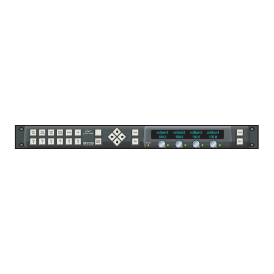
Section 4 — Operation Newton Panel Description A general overview of each component and its operation on the panel is given below. Refer to the rack mount panel (Figure 54) and software panel (Figure 55) illustrations. Figure 54. Newton Rack Mount Panel Control Surface Not currently supported Enable button Bright... -
Page 71: Enable Button
Newton Panel Description Enable Button This button enables or disables the control panel surface communication with the modules. When disabled (button tally off) rotating a knob or pushing a button does not affect any modules. This prevents knobs from being adjusted inadvertently causing unwanted parameter changes. When enabled (high tally) the knobs will communicate with the modules and adjust the assigned parameters. -
Page 72: Identify Button
Section 4 — Operation Identify Button When the button is selected (high tally or LED on), the display IDENTIFY shows information about the panel, the panel controls, and the currently loaded configuration. This includes channel name, current setup name, knob assignment information (if knob is configured) and parameters and ranges of adjustment. -
Page 73: Soft Keys
Newton Panel Description Soft Keys There are twelve soft key buttons on the panel that allow the user to either recall setups assigned to a soft key or scroll through an index of setups from the Newton Panel Configurator application. The soft keys are used in con- junction with the button(s) on the panel as described next. - Page 74 Section 4 — Operation When no setup assignment has been made for a corresponding index entry in the Newton Panel Configurator, selecting the soft key will show a Not Currently Active message (Figure 58). The display in the figure indicates the Index entry for Index Key 10 has not been created in Newton Panel Configurator.
- Page 75 Newton Panel Description Enable Soft Key (Recall) mode When the button is on (enabled), selecting soft keys will recall RECALL user-assigned setups. If soft key assignments have been made in the Newton Panel Configurator and downloaded to a panel, or made at the panel after the configuration was downloaded, when the button on RECALL...
-
Page 76: Learn Button
Section 4 — Operation Learn Button button enables the soft key assignment mode. When the Learn Learn button green LED is lit on the soft panel or the button is held Learn/Recall down on the rack mount panel, you may learn the present setup in the display to one of the soft key buttons on the panel. - Page 77 Newton Panel Description 3. Select the Enable button. The parameters for the setup to be assigned to a soft key should appear above the knobs. 4. Select the Learn button to the right of the soft keys. The display will instruct you to press the soft key to use with this setup (Figure 61).
- Page 78 Section 4 — Operation To make soft key assignments from the rack mount panel: 1. On the Newton rack mount panel, select the IDENT button and scroll to the desired setup with the left and right arrow navigation keys. 2. Select the ENABLE button. The parameters in the selected setup should be displayed (Figure 62).
- Page 79 SpeciÞcations Table 3. Newt-PC and Newt-RM Specifications Parameter Value Newton Software Control Panel Platforms Windows XP, 2000 or NT 4.0 Web browser Internet Explorer v5.5 or later Monitor Resolution Minimum 1024 x 768 Newton Rack Mount Control Panel Connectors RJ-45 10/100 BaseT Ethernet Height 1.7 in.
- Page 80 Specifications Newton Instruction Manual...
- Page 81 Index Numerics recalling FAQ database 2000NET module frequently asked questions software requirements 8900NET module software requirements General Configuration tab Grass Valley website Accelerate button acceleration of knob controls Identity (Ident) button installation rack mount panel channels software panel adding configuration error message revising knob LEDS...
- Page 82 Index Associate Router Source checkbox installation Load Config File button monitor settings Local Panel (NewtonPC) checkbox operation New Channel button overview New Config button specifications New Setup button system requirements operational overview Other tab overview Read from Panel button uninstalling software Router Configuration tab Router Source Name Save Config File button...
Need help?
Do you have a question about the Grass Valley Newton and is the answer not in the manual?
Questions and answers