Table of Contents
Advertisement
Quick Links
Advertisement
Table of Contents

Subscribe to Our Youtube Channel
Related Manuals for Seanix Kootenay

Summary of Contents for Seanix Kootenay
- Page 1 Kootenay (SEA440LX) Motherboard User Manual Version 1.0b...
- Page 2 In no event shall Seanix be liable for any loss or profits, loss of business, loss of use or data, interruption of business, or for...
-
Page 3: Table Of Contents
TABLE OF CONTENTS 1.PRODUCT DESCRIPTION................ 5 ..............5 EATURES OF THE OOTENAY OTHERBOARD ..................... 7 OTHERBOARD AYOUT ......................8 ONNECTORS ....................8 ENTRAL ROCESSING ........................... 8 EMORY ........................ 9 ACHE EMORY 82443LX PCI/A.G.P. (PAC)..............9 NTEL CONTROLLER 82371AB PCI ISA IDE X (PIIX4) ............ - Page 4 3.USING THE BIOS SETUP PROGRAM........... 24 CMOS S ....................27 TANDARD ETUP CMOS S ....................29 DVANCED ETUP ....................32 DVANCED HIPSET ETUP ..................35 OWER ANAGEMENT ETUP PCI / P ................... 38 LUG AND ETUP ......................41 ERIPHERAL ETUP ....................
-
Page 5: Product Description
The Intel 440LX AGPset - which makes AGP support possible - also provides additional advanced capabilities including SDRAM support, Ultra DMA/33, and Dynamic Power Management Architecture. Memory support to 384 MBytes, along with enhanced manageability, and it’s clear why the Kootenay motherboard is the ideal choice for ® Pentium II processor-based systems. - Page 6 • Two USB connectors. • Onboard AGP connector that supports add-in A.G.P. cards. • Optional hardware monitor that integrates a temperature sensor, fan speed headers, power supply voltage monitor and support for chassis intrusion. • Optional Onboard LAN using the Intel 558 chipset to provide Wake-On-LAN capability.
-
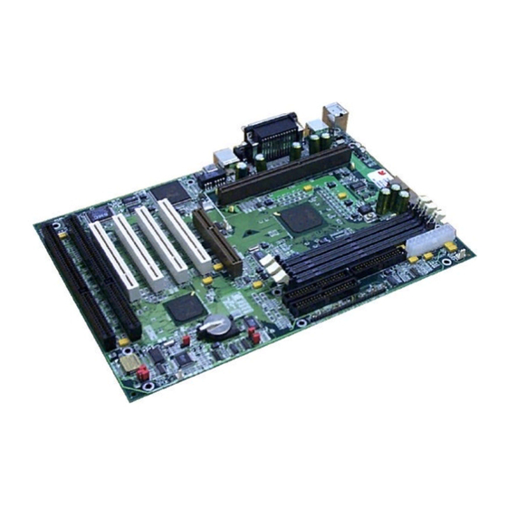
Page 7: Motherboard Layout
Motherboard Layout. -
Page 8: Port Connectors
Port Connectors Central Processing Unit ® This motherboard is designed to operate with a single Intel Pentium II microprocessor. The Pentium II processor includes the following features: • Intel's highest performance processor, combining the power of the Pentium ® processor with the capabilities of MMX™ technology. •... -
Page 9: Cache Memory
• Supports 8 MBytes, 16 MBytes, 32 MBytes, 64 MBytes, and 128 MBytes modules. Cache Memory The Pentium II microprocessor includes 32 KByte (16K/16K) non-blocking level one cache and 512 KByte unified, non-blocking level two cache on the substrate in the Single Edge Connector (S.E.C.) cartridge. -
Page 10: Universal Serial Bus (Usb)
and is intended for exclusive use with graphical-display devices. A.G.P. provides these performance features: • Pipelined-memory read and write operations that hide memory access latency. • Demultiplexing of address and data on the bus for near 100 percent bus efficiency. •... -
Page 11: Super I/O Controller
An external coin-cell battery powers the real-time clock and CMOS content. When the computer is not plugged into a wall socket, the battery has an estimated life of three years. When the computer is plugged in, the 3.3 V standby current from the power supply extends the life of the battery. -
Page 12: Bios System Support
Keyboard and Mouse Interface PS/2 keyboard and mouse connectors are located on the back panel. The 5 V lines to † these connectors are protected with a PolySwitch circuit that, like a self-healing fuse, reestablishes the connection after an over-current condition is removed. Power to the computer should be turned off before a keyboard or mouse is connected or disconnected. - Page 13 PCI IDE 1. “Ultra DMA/33” Synchronous DMA IDE support. 2. Meets Microsoft requirement for PC97. 3. Fully compatible with PCI spec.V2.1. 4. Supports PCI Bus Mastering. 5. Supports Mode 3 and Mode 4 for Enhanced IDE specification. 6. Supports Multi-word DMA mode 0,1,2. 7.
-
Page 14: Expansion Slots
The flash upgrade process can be done by running a utility from a diskette or hard disk, or over a network. WARNING For information about the latest BIOS update for the Kootenay, contact your service representative. Expansion Slots This motherboard has two 16-bit ISA slots, four PCI expansion slots and an AGP slot that supports A.G.P. -
Page 15: Onboard Lan
This slot shares the PCI Interupt used by the USB port. Onboard LAN The onboard LAN for the Kootenay motherboard is driven by the Intel 82558 chipset. The Intel82558 is a 10/100 MBps PCI Ethernet LAN Controller. It automatically detects between 10 Base-T or 100 Base-TX Fast Ethernet connections. -
Page 16: Front Panel Connector
Front Panel Connector PWR ON Pins 1 & 2, connected to Standby Switch via twisted pair cable. Pins 3 & 4, connected to Sleep Switch via twisted pair cable (orange/white). INFRARED Pins 6-11, not currently used. HD LED Pins 15 & 16, connected to the HDD LED via twisted pair cable (red/white). -
Page 17: Ls-120 Support
1.44 MBytes and 720 KB DOS-formatted diskettes and is supported by Windows 95 and Windows NT operating systems. The Kootenay motherboard allows connection of an LS-120 compatible drive and a standard 3.5-inch diskette drive. The LS-120 drive can be configured as a boot device, if selected in the BIOS setup utility. -
Page 18: Installation And Settings
2.Installation and Settings CAUTION Electrostatic discharge (ESD) can damage components. Perform the procedures described in this chapter only at an ESD workstation. If such a station is not available, you can provide some ESD protection by wearing an antistatic wrist strap and attaching it to a metal part of the computer. - Page 19 Flash Device Mode Settings Mode *Prog. Dev Write Protect To clear the BIOS password do the following: • Power down the system. • Remove the system cover to access the motherboard. • Change the setting of J18 to 2-3 (see the motherboard layout for it’s location). •...
-
Page 20: Cpu Installation
CPU Installation Installing the Retention Mechanism NOTE To install the retention mechanism, you need a Phillips (#2 bit) manual torque screwdriver capable of a 6.0 in.-lb. ± 1.0 in.-lb. (0.678 N-m ± 0.113 N-m) setting. The screwdriver also must have a shaft longer than 2 inches. To install the retention mechanism, follow these steps: 1. - Page 21 Installing the Processor To install the processor, follow these steps: 1. Insert the processor in the retention mechanism (A). 2. Press down on the processor until it is firmly seated in the SIot 1 connector and the latches (B) on the processor lock into place. The CPU Heatsink may not appear as shown in the illustrations.
-
Page 22: System Memory Installation
System Memory Installation You can install from 8 MBytes to 384 MBytes of memory in the motherboard DIMM sockets. The board has DIMM sockets arranged as banks 0, I, and 2. The motherboard supports the following memory features: • 168-pin 3.3 V EDO DIMMs. •... -
Page 23: Battery Replacement
3. Reinstall and reconnect any parts you removed or disconnected to reach the DIMM sockets. Battery Replacement When your computer is turned off, a lithium battery keeps the time-of-day clock and the values in CMOS RAM current. The battery should last about seven years. When battery begins to die, it loses voltage;... -
Page 24: Using The Bios Setup Program
3.Using the BIOS Setup Program This chapter tells how to use the Setup program that is built into the BIOS. The Setup program makes it possible to change configuration information (such as the types of peripherals that are installed) and the boot-up sequence for the system. The Setup information is stored in CMOS random access memory (RAM) and is backed up by a battery when power is off. - Page 25 AMIBIOS HIFLEX SETUP UTILITY – VERSION 1.19 © 1996 American Megatrends, Inc. All Rights Reserved Standard CMOS Setup Advanced CMOS Setup Advanced Chipset Setup Power Management Setup PCI / Plug and Play Setup Peripheral Setup Hardware Monitor Setup Auto-Detect Hard Disks Change User Password Change Supervisor Password Auto Configuration with Optimal Settings...
- Page 26 Overview of the Setup Keys The following keys have special functions in the AMI BIOS Setup Utility. Setup Key Description <Tab> Move to the next field. <Esc> Closes the current operation and return to the previous level. <Enter> Selects the current item or option. Increments a value.
-
Page 27: Standard Cmos Setup
Standard CMOS Setup AMIBIOS SETUP – STANDARD CMOS SETUP © 1996 American Megatrends, Inc. All Rights Reserved Date (mm:dd:yy) : Fri, Jan 21, 1998 Base Memory : 640 KB Time (hh:mm:ss) : 16 : 38 : 13 Extd Memory : 63 MBYTES Floppy Drive A: 1.44 MBYTES 3½... - Page 28 Primary IDE Master, Primary IDE Slave, Secondary IDE Master, Secondary IDE Slave Choose these options to configure the hard disk drive shown in the field. When you select an option, the following parameters are listed: Type, LBA/Large Mode, Block Mode, 32Bit Mode, and PIO Mode. Use the cursor to highlight “Type” and then choose “Auto”...
-
Page 29: Advanced Cmos Setup
Advanced CMOS Setup AMIBIOS SETUP – ADVANCED CMOS SETUP © 1996 American Megatrends, Inc. All Rights Reserved Quick Boot Disabled Available Options : Boot Device Floppy Disabled Boot Device IDE-0 IDE-0 Boot Device CDROM IDE-1 4th Boot Device Disabled IDE-2 Try Other Boot Devices IDE-3 Floppy Access Control... - Page 30 Boot Sequence (Boot Devices 1-4). Set this option to the sequence of boot drives (floppy drive A:, hard disk drive C:, CD-ROM drive, SCSI hard-drive, Floptical or Network) that the AMI BIOS attempts to boot from after AMI BIOS POST completes. The default setting is “A, C, CD-ROM”.
- Page 31 PS/2 Mouse Support Set this option to enable or disable the system detecting and assigning an IRQ to a PS/2 mouse. The default setting is “Enabled”. Primary Display This option specifies the type of display monitor and adapter in the computer. The settings are Mono, CGA40, CGA80, EGA/VGA, or Absent.
-
Page 32: Advanced Chipset Setup
Advanced Chipset Setup AMIBIOS SETUP – ADVANCED CHIPSET SETUP © 1996 American Megatrends, Inc. All Rights Reserved Auto Configure EDO DRAM Timing:Enabled Available Options : EDO DRAM Speed (ns) Disabled EDO Read Burst Timing x222 Enabled EDO Write Burst Timing x222 EDO RAS Precharge Timing 3 clocks... - Page 33 • EDO Read Burst Timing - This option specifies the timings for EDO DRAM system memory for Read operations in burst mode. The settings are x222 or x333. The Optimal default setting is x222. • EDO Write Burst Timing - This option specifies the timings for EDO DRAM system memory for Write operations in burst mode.
- Page 34 resolve the problem. Most DRAM errors are soft errors. If a hard (uncorrectable) error occurs, writing the fixed data back to DRAM system memory does not solve the problem. In this case, the second time the error occurs in the same location, a Parity Error is reported, indicating an uncorrectable error.
-
Page 35: Power Management Setup
Power Management Setup AMIBIOS SETUP – POWER MANAGEMENT SETUP © 1996 American Megatrends, Inc. All Rights Reserved Power Management / APM Enabled Available Options : Green PC Monitor Power State Stand By Disabled Video Power Down Mode Suspend Enabled Hard Disk Power Down Mode Stand By Standby Time Out (Minute) Disabled... - Page 36 This section describes the Setup options available in the Power Management Setup menu used to configure the power conservation features. If you select certain options the Setup program switches to a sub-screen for the selected option. Power Management Power Management allows the user to reduce power consumption. Set this option to “Enabled”...
- Page 37 Display Inactivity This option specifies if AMIBIOS is to monitor activity on the display monitor for power conservation purposes. When this options set to Monitor and there is no display activity for the length of time specified in the value in the Full-On to Standby Timeout (Min) option, the computer enters a power saving state.
-
Page 38: Pci / Plug And Play Setup
PCI / Plug and Play Setup AMIBIOS SETUP – PCI / PLUG AND PLAY SETUP © 1996 American Megatrends, Inc. All Rights Reserved Plug and Play Aware O/S Available Options : Onboard LAN Controller Enabled PCI Latency Timer (PCI clocks) PCI VGA Palette Snoop Disabled Allocate IRQ to PCI VGA... - Page 39 Plug and Play Aware OS Set this option to “Yes” if the operating system installed in the computer is Plug and Play-aware. AMI BIOS only detects and enables PnP ISA adapter cards that are required for system boot. The Windows 95 operating system detects and enables all other PnP-aware adapter cards.
- Page 40 PCI IDE BusMaster Set this option to Enabled to specify that the IDE controller on the PCI local bus has bus mastering capability. The settings are Disabled or Enabled. The Optimal and Fail- Safe default setting is “Disabled”. • PCI Slot1 IRQ Priority •...
-
Page 41: Peripheral Setup
Peripheral Setup AMIBIOS SETUP – PERIPHERAL SETUP © 1996 American Megatrends, Inc. All Rights Reserved OnBoard FDC Auto Available Options : OnBoard Serial Port 1 Auto Auto OnBoard Serial Port 2 Auto Disabled Serial Port 2 Mode Normal Enabled Serial Port 2 Duplex Mode Serial Port 2 Receiver Polarity N/A Serial Port 2 Xmitter Polarity OnBoard Parallel Port... - Page 42 Serial Port2 Mode This option specifies the operating mode for serial port 2.This option only appears if the Onboard Serial Port2 option is not set to Auto or Disabled. The settings are IR (infrared) or Normal. The Optimal and Fail-Safe default settings are Normal. Duplex Mode This option specifies the type of duplexing used for infrared on serial port 2.
-
Page 43: Hardware Monitor Setup
Hardware Monitor Setup AMIBIOS SETUP – HARDWARE MONITOR SETUP © 1996 American Megatrends, Inc. All Rights Reserved System Hardware Monitor Available Options : Current CPU Temperature 33°C/91°F Current System Temperature 30°C/86°F Current CPU Fan Speed 4166 RPM Current Case Fan 1 Speed 0 RPM Current Case Fan 2 Speed 0 RPM... -
Page 44: Auto-Detect Hard Disks
Auto-Detect Hard Disks This “Auto-Detect Hard Disks” option detects the parameters of IDE hard disk drives, and automatically enters them into the standard CMOS setup screen. Change User Password & Change Supervisor Password AMI BIOS has two optional password features. “Supervisor Password” sets a password that will be used to protect the system and the setup utility;... -
Page 45: Save Settings And Exit
Save Settings and Exit Saves the changes to CMOS RAM and exits the Setup program. You can also press the <F10> key anywhere in the BIOS Setup program (main menu) to do this. Exit Without Saving Exits the Setup program without saving any changes. This means that any changes made while in the Setup program are discarded and NOT SAVED. -
Page 46: Error And Information Messages
4.Error and Information Messages This chapter describes the following: • Jumper block locations and functions • Procedures to remove and install optional components • Information about replacing the battery Before You Begin • Be sure to do each procedure in the correct order. •... -
Page 47: Beep Codes
Add-in boards can be extremely sensitive to ESD and always require careful handling. After removing the board from its protective wrapper or from the system, place the board flat on a grounded, static-free surface, component-side up. Use a conductive foam pad if available, but not the board wrapper. Do not slide the board over any surface. -
Page 48: Error Messages
Error Messages An error can occur after the system display has been initialized. Error Message Explanation 8042 Gate-A20 Error Gate A20 on the keyboard controller (8042) is not working. Replace the 8042. Address Line Short! Error in the address decoding circuitry on the motherboard. - Page 49 Error Message Explanation DMA 1 Error Error in the first DMA channel. DMA 2 Error Error in the second DMA channel. FDD Controller Failure AMIBIOS cannot communicate with the floppy disk drive controller. Check all appropriate connections after the system is powered down. HDD Controller Failure AMIBIOS cannot communicate with the hard disk drive controller.
-
Page 50: Glossary
5.Glossary ADDRESS: Specific location in the memory of the computer where information about programs, data and software drivers is stored. Peripheral devices such as mouse, modems, etc. require a specific I/0 port address and interrupt in order to function properly. BIOS:(BASIC INPUT OUTPUT SYSTEM) That part of a ROM that is the interface between the system hardware and the operating system. - Page 51 CONFIG.SYS: A file usually located in the root directory of the boot disk that contains information required to load installable device drivers and other system configuration parameters. CONVENTIONAL MEMORY: System main memory from 0 to 640KB. Many programs run in this area. COPROCESSOR: An auxiliary processor that reduces microprocessor overhead and increases system speed by executing certain math related functions.
- Page 52 INTERRUPT: Special operation used by hardware peripheral devices to allow them to communicate with the Central Processing Unit. Each peripheral device is allocated a unique interrupt nuMByteser which the CPU recognizes when talking to the device. ISA: Industry Standard Architecture. JUMPER: A patch cable, wire or other such device used to establish a circuit.
Need help?
Do you have a question about the Kootenay and is the answer not in the manual?
Questions and answers