Table of Contents
Advertisement
Quick Links
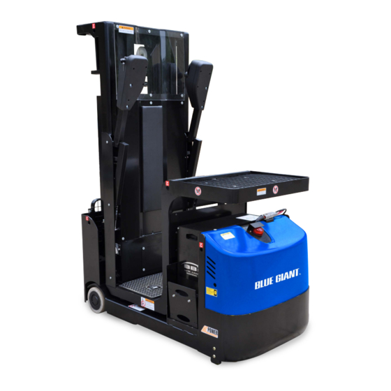
OWNER'S MANUAL
BG1 TASK SUPPORT VEHICLE
ACTUAL PRODUCT MAY NOT APPEAR EXACTLY AS SHOWN
WARNING
Do not operate or service this product unless you have
read and fully understand the entire contents of this
manual. Failure to do so may result in property damage,
bodily injury or death.
ISSUE DATE: DECEMBER 7, 2020 REV.1.0 (PART # 038-XXXXE)
Advertisement
Table of Contents
Troubleshooting

Related Manuals for Blue Giant BG1

Summary of Contents for Blue Giant BG1
- Page 1 OWNER’S MANUAL BG1 TASK SUPPORT VEHICLE ACTUAL PRODUCT MAY NOT APPEAR EXACTLY AS SHOWN WARNING Do not operate or service this product unless you have read and fully understand the entire contents of this manual. Failure to do so may result in property damage, bodily injury or death.
- Page 2 WARNING Do not operate this vehicle unless you have been Before elevating platform be sure guardrail access authorized and trained to do so, and have read all gates are in place and lowered. Keep feet on platform warnings and instructions in Operator’s Manual and on floor at all times while using vehicle, never climb onto this vehicle.
-
Page 3: Table Of Contents
Section Page Section Page 6-2.1 REMOVAL ..........6-2 1 DESCRIPTION ...........1-1 6-2.2 INSTALLATION ........6-2 1-1 INTRODUCTION ........1-1 6-3 DRIVE WHEEL ...........6-2 6-4 CASTER.............6-2 1-2 GENERAL DESCRIPTION ......1-1 1-3 DATA PLATE AND WARNING DECAL..1-2 7 ELEVATION SYSTEM SERVICING ....7-1 1-4 INSTALL /WARRANTY CHECK LIST ..1-2 7-1 GENERAL...........7-1 7-2 LIFT CHAIN LENGTH ADJUSTMENT ..7-1 2 PLANNED MAINTENANCE........2-1... -
Page 5: Description
SECTION 1 DESCRIPTION 1-1. INTRODUCTION. 1-2. GENERAL DESCRIPTION. This publication describes the 24 volt BG1 task The self-propelled BG1 task support vehicle lifts support vehicle by Blue Giant. Included are planned transports 1,000 pounds capacity maintenance instructions, lubrication procedures, including load and operator. The vehicle enables... -
Page 6: Data Plate And Warning Decal
Blue Giant 1-4. INSTALLATION / WARRANTY CHECK LIST. Blue Giant initiate Blue 1-3. DATA PLATE AND WARNING DECAL. Giant R6978 Figure 1-2 BG1 Data Plate... - Page 7 RGA# A confirmation receipt will be faxed back with a warranty claim number attached. If Blue Giant deems that part(s) need to be returned, an RGA numbered form will be faxed as well. Please include a copy of the RGA form with returning part(s) to Blue Giant Brampton location only.
- Page 8 NOTES...
-
Page 9: Planned Maintenance
1. If purchased used unless it's enclosed area well when charging. determined that the frequent and annual inspections are current. 2. The BG1 Task Support Vehicle has CAUTION: Batteries contain sulfuric acid which may been in service for three (3 months or 150 hours, cause severe burns. -
Page 10: 2-5.2 Safety Rules
2-5.2. Safety Rules Charge the battery only in areas designated for that use. • Wear protective clothing, such as rubber apron, Battery terminals should be checked and cleaned gloves, boots and goggles when performing any of corrosion regularly. Good battery terminal maintenance on batteries. -
Page 11: Charging Batteries
Figure 2-1 Battery Charging 2-7. REPLACING BATTERIES Replace only with original OEM batteries or batteries R6987 approved by an authorized Blue Giant dealer. Figure 2-2 Battery Replacement Contact your authorized Blue Giant dealer for information on optional batteries and battery chargers. -
Page 12: Lubrication
R6115 2-8. LUBRICATION. Refer to Table 2-2 for the recommended types of Table 2-2 Recommended Lubricants grease and oil. Table 2-3 in conjunction with (See Table 2-3 for Application) Figure 2-3 identifies the items requiring lubrication. No. 1 Grease—Polylub GA352P 2-9. - Page 13 R6988 Figure 2-3 Lubrication Diagram Table 2-3 Lubrication Chart FIG 3-2 LOCATION METHOD OF TYPE APPLICATION INDEX APPLICATION (Table 2-3) LUBRICANT Mast Spray No. 1 Full length of channel where rollers operate. Hydraulic Reservoir No. 2 With platform fully lowered, fill reservoir with hydraulic oil to level on dip stick.
- Page 14 2. The BG1 Task Support Vehicle has been in service for three (3) months or 150 hours, whichever comes first. 3. The BG1 Task Support Vehicle has been out of service for a period longer than three (3) months.
- Page 15 Annual Inspec�on Report VEHICLE INFORMATION: MODEL: SERIAL: MAST SIZE: HOUR METER: DEALER: OWNER / END USER: HYDRAULIC SYSTEM Li� cylinder is free of damage, no evidence of leaks and that all hardware is secure and undamaged. All hydraulic hoses, fi�ngs and components are properly secured and that there is no evidence of leaks. Ensure fluid level is correct in hydraulic tank.
- Page 16 NOTES...
-
Page 17: Troubleshooting
SECTION 3 TROUBLESHOOTING 3-1. GENERAL Operate: Vehicle Does Not Operate Forward or Reverse: Trouble With Braking: Trouble With Lifting Or Table 3-1 as a guide to determine possible Lowering, and Miscellaneous malfunctions. causes of trouble. The table is divided into five main categories: Vehicle and Hydraulic System Will Not Table 3-1 Troubleshooting Chart MALFUNCTION... - Page 18 Table 3-1 Troubleshooting Chart - Continued MALFUNCTION PROBABLE CAUSE CORRECTIVE ACTION TROUBLE WITH LIFTING OR LOWERING Oil sprays or flows from the top of Defective packing in lift cylinder Repair lift cylinder. the lift cylinder. Squealing sounds when lifting a. Oil level too low. Identify oil leak and fill reservoir.
- Page 19 Table 3-1 Troubleshooting Chart - Continued MALFUNCTION PROBABLE CAUSE CORRECTIVE ACTION TROUBLE WITH LIFTING OR LOWERING - Continued Forks drifts down under load when Leak in hydraulic system, lift cylin- Check for leaking fitting in in a raised position. der or lowering valve. hydraulic line and repair as required.
-
Page 20: Controller Troubleshooting
The Zapi Press the ROLL down button (2) or the ROLL up Handset is avail-able through your Blue Giant button (1) until ALARMS menu appears on the dealer. If you require dealer location information, display. -
Page 21: 3-2.4 Factory Settings
Parameter setting are not to be changed from Press the SET up button (5) or the SET down factory settings without explicit written permission from Blue Giant. To verify the button (6) until the factory setting is reached. parameter settings proceed as follows and refer to Press the OUT button (4) to exit the parameters. - Page 22 So ask for the Then it is necessary to specify if the assistance of a Blue Giant Service controller is AC-0 or AC-1 type (see Repre-sentative when this alarm AC TYPE 0 in the hidden hardware occurs.
- Page 23 First, check for the failure mode. Then contact the Blue Giant Service Representative to look for a counter-measure. This alarm may occur for a HW failure.
- Page 24 Table 3-3 Troubleshooting Chart (Traction/Lift Controller) - Continued ERROR ERROR TEXT POSSIBLE CAUSE FAULT CLEARANCE I=0 EVER This test is carried out when the motor is If everything is OK for the motor, the running, and it verifies that the current problem could be in the related circuit.
- Page 25 Table 3-3 Troubleshooting Chart (Traction/Lift Controller) - Continued ERROR ERROR TEXT POSSIBLE CAUSE FAULT CLEARANCE CAPACITOR CHARGE In working condition, a resistance The possibilities: connected between the key and the Rail Capacitors, keeps the Rail Another device, connected in Capacitors charged before the Main parallel with the Rail Capacitors, Contactor closes.
- Page 26 Table 3-3 Troubleshooting Chart (Traction/Lift Controller) - Continued ERROR ERROR TEXT POSSIBLE CAUSE FAULT CLEARANCE DRIVER SHORTED This alarm occurs when the voltage on Replace the controller. the main contactor is higher than expected. This means that the main contactor coil has a high voltage although it is not supplied.
- Page 27 Table 3-3 Troubleshooting Chart (Traction/Lift Controller) - Continued ERROR ERROR TEXT POSSIBLE CAUSE FAULT CLEARANCE PEDAL WIRE KO The SW continuously checks for the Check the voltage on NPOT (CNB#11) connection of the two supply ends of and the potentiometer connections. the potentiometer in the accelerator.
- Page 28 Ask for the assistance of a Blue Giant Service Representative when alarm occurs. CHECK UP NEEDED This is just a warning to perform It is just enough to turn the CHECK UP programmed maintenance.
- Page 29 Table 3-4 Troubleshooting Chart (EPS-AC0 Controller) ERROR ERROR TEXT POSSIBLE CAUSE FAULT CLEARANCE SERIAL ERR #1 Main uC and Slave uC communicate via Replace the controller. a local serial interface. This alarm occurs when the slave uC does not receive the communication from the main uC through the serial interface.
- Page 30 Table 3-4 Troubleshooting Chart (EPS-AC0 Controller) - Continued ERROR ERROR TEXT POSSIBLE CAUSE FAULT CLEARANCE HIGH TEMPERATURE This alarm occurs if the temperature od Improve the cooling of the controller; the controller base plate overtakes 75 otherwise replace the controller. degrees.
- Page 31 Table 3-4 Troubleshooting Chart (EPS-AC0 Controller) - Continued ERROR ERROR TEXT POSSIBLE CAUSE FAULT CLEARANCE CLOCK PAL NOT OK The main uC send an analog signal Replace the controller. towards the salve uC to reset the slave uC on demand. When the slave uC detects this analog signal external to a window from 2.2 to 2.8 and not in the range to generate the reset on...
- Page 32 Table 3-4 Troubleshooting Chart (EPS-AC0 Controller) - Continued ERROR ERROR TEXT POSSIBLE CAUSE FAULT CLEARANCE FB POT LOCKED In application with a feedback In application with the feedback with the potentiometer, this alarm occurs if the feedback potentiometrer, verify the feed-back potentiometer (CPOT on feedback potentiometer is not CNB#6) does not change (or changes...
- Page 33 Table 3-4 Troubleshooting Chart (EPS-AC0 Controller) - Continued ERROR ERROR TEXT POSSIBLE CAUSE FAULT CLEARANCE POSITION ERROR This alarm occurs for an error in the Check the potentiometer connected to redundant test o the feedback sensors. CNB#6 is working correctly. If toggle switches are connected to CNA#2 and CNA#3, verify that they are working correctly and setting AUX FUNCTION...
- Page 34 DATA ACQUISITION This alarm occurs when acquiring the Recycle the key. motor resistance or when adjusting the parameters to compensate for the gain of the current amplifiers (maximum current factory adjusted). GAIN EEPROM KO The parameter to compensate for the Replace the controller.
- Page 35 MICRO SLAVE It occurs when the information on the Replace the controller. status bus between the main uC and the slave uC is frozen to the 0xFF value (the slave uC does not update the status bus configuration). KM OPEN This alarm occurs if the slave uC detects Replace the controller.
- Page 36 NOTES...
-
Page 37: Steering System
SECTION 4 STEERING SYSTEM 4-1. CONTROL ARM Remove the six screws from the lower cover. Separate lower cover and upper cover. 4-1.1. Steering Control Removal. Engage the emergency power disconnect switch and turn off key switch. R8163 Figure 4-1 Control Arm (Left) -
Page 38: 4-1.2 Steering Control Installation
Disconnect the two harnesses from each other Engage the emergency power disconnect switch and from the potentiometer. and turn off key switch. Remove button plug, nut, lock washer, handle and Remove two screws. shims. Carefully lift cover up and off the truck. Remove four screws, four lock washers and 4-2.2. -
Page 39: 4-3.2 Motor Installation
R8161 Figure 4-3 Drive System Disconnect harness and cables from the steer Secure the motor with two screws two lock motor. washers and two flat washers from under the vehicle. Remove three screws three lock washers and three flat washers from under the vehicle. Reconnect harness and cables to the steering motor. - Page 40 NOTES...
-
Page 41: Brake Servicing
SECTION 5 BRAKE SERVICING 5-1. BRAKES. Disconnect electric brake from main harness. Remove the mounting screws and brake. The brake system consists of a drive motor mounted brake. This brake is spring applied and electrically Place the new brake into position and secure with released. - Page 42 R8161 Figure 5-1 Transmission, Motor & Brake Assembly...
-
Page 43: Transmission, Drive Wheel, Load Wheel And Casters
SECTION 6 TRANSMISSION, DRIVE WHEEL, LOAD WHEEL, CASTERS 6-1. Transmission and Drive Motor. Disconnect electric brake from harness. Disconnect cables from drive motor. Engage the emergency power disconnect switch and turn off key switch. Disconnect encoder from drive motor. Remove the compartment cover as described in Support the drive assembly and remove six paragraph 4-2.1. -
Page 44: Load Wheel
6-2. Load Wheel. Install cover and secure with four screws. Remove the blocking from under the vehicle and 6-2.1. Removal lower it to the ground. Engage the emergency power disconnect switch Disengage the emergency power disconnect and turn off key switch. switch and turn on key switch. - Page 45 DT_0001 Figure 6-2 Frame...
- Page 46 R8161 Figure 6-3 Transmission, Motor & Brake Assembly...
-
Page 47: Elevation System Servicing
SECTION 7 ELEVATION SYSTEM SERVICING 7-1. GENERAL. The elevation system includes the outer mast, inner mast, lift linkage, drag chains, lift chains, lift cylinder and ram head. 7-2. LIFT CHAIN LENGTH ADJUSTMENT. Fully lower the Platform. Engage the emergency power disconnect switch and turn off key switch. -
Page 48: Lift Chain Wear Inspection
7-3. LIFT CHAIN WEAR INSPECTION. Remove cotter pin, flat washer and clevis pin connecting chain to adjusting screw at the The lift chain should be replaced when it is worn outer mast. enough to increase it’s length by 3% or more. On Remove chain from sheave. - Page 49 R8172 Figure 7-2 Elevation System - Part 1...
- Page 50 R8173 Figure 7-3 Elevation System - Part 2...
- Page 51 R8174 Figure 7-4 Platform Installation...
-
Page 52: Lift Cylinders
7-5. LIFT CYLINDERS. NOTE: Removal and repair of lift cylinders are cov- ered in SECTION... -
Page 53: Hydraulic System Servicing
SECTION 8 HYDRAULIC SYSTEM SERVICING 8-1. LINES AND FITTINGS 8-2. HYDRAULIC PUMP, MOTOR, AND RESER- VOIR ASSY WARNING: When the platform is raised, pressure hydraulic pump/motor assembly exists in the hydraulic system lines and disassembled and repaired. However, a defective fittings. - Page 54 R8165 Figure 8-1 Hydraulic System...
-
Page 55: Installation
8-2.3. Installation Disconnect the hose (13, Figure 8-3) from tube (14). Position pump/motor assembly on reservoir and Remove screw (16), lock washer (17), flat washer install four screws, four lock washers and four flat (18) and disconnect tube (14) from connector washers. - Page 56 Install bushing (14), sheave (13) on angle (11) and secure with bolt (12), lock washer (9) and flat washer (10). Install lift chains as described in paragraph 7-4. Lift inner mast (11) and remove the blocking. Fill the hydraulic reservoir. Use hydraulic oil listed Table 2-2.
- Page 57 R8176 Figure 8-3 Hydraulic Lines...
- Page 58 R8172 Figure 8-4 Elevation System - Part 1...
- Page 59 RR8173 Figure 8-5 Elevation System - Part 2...
-
Page 60: Lift Cylinder (Three Stage Mast Secondary)
11. Operate the lift and lower buttons to refill the Remove screw (11, Figure 8-6) and washer (12). cylinder and lines with hydraulic oil. Remove gland nut (3). 12. Check level of hydraulic oil. If required, add Remove wiper ring (1), packing (2) and O-rings (4 hydraulic oil to bring to proper level. -
Page 61: Installation
8-4.3. Installation Disengage the emergency power disconnect switch and turn on key switch. Position the cylinder (6, Figure 8-4) on the frame. Operate the lift and lower buttons to refill the Lift middle mast (2) and remove the blocking. cylinder and lines with hydraulic oil. Install two bolts (3), two lock washers (4), and two 10. - Page 62 NOTES...
-
Page 63: Electrical Components
SECTION 9 ELECTRICAL COMPONENTS 9-1. ELECTRICAL CONTROL PANEL Remove the compartment cover as described in paragraph 4-2. 9-1.1. Maintenance Tag and disconnect all electrical cables and harness from control panel. NOTE: Erratic operation of the vehicle may be caused by defective controller components. Remove four screws, four lock washers, four flat Before removing the electrical panel, perform washers and panel. - Page 64 R8167 Figure 9-1 Electrical System...
-
Page 65: Lowering Buzzer Replacement
9-3. LOWERING BUZZER REPLACEMENT. 10. Install the battery as described in paragraph 2-7. 11. Disengage the emergency power disconnect Engage the emergency power disconnect switch switch and turn on key switch. and turn off key switch. Remove the compartment cover as described in 9-6. -
Page 66: Platform Cable Replacement
9-9. Platform CABLE REPLACEMENT. 11. Remove two screws (23, Figure 9-3) and disconnect mount (25) from bracket (26). 9-9.1. Three Stage Mast 12. Disconnect protective chain (30) from mount (25). NOTE: The Three Stage Mast version uses two 13. Lift harness with protective chain (30) from protective chains for the mast harness. - Page 67 R8172 Figure 9-2 Elevation System - Part 1...
- Page 68 R8173 Figure 9-3 Elevation System - Part 2...
- Page 69 R8174 Figure 9-4 Platform Installation...
- Page 70 R8175 Figure 9-5 Platform Assembly...
-
Page 71: Optional Equipment
SECTION 10 OPTIONAL EQUIPMENT 10-1. INDUSTRIAL BATTERY Contact you authorized Blue Giant dealer for information on optional batteries and battery chargers. - Page 72 NOTES...
-
Page 73: Illustrated Parts Breakdown
SECTION 11F ILLUSTRATED PARTS BREAKDOWN Following is an illustrated parts breakdown of assemblies and parts associated with the BG1 task support vehicle. 11-1... - Page 74 DT_0001 Figure 11-1 Frame...
- Page 75 Frame QTY. POS. PART NUMBER DESCRIPTION NOTES REQD. 0000-000877-00 SEAL WASHER 60×85×8 0000-000961-00 BEARING CK11-140001-10 LOAD WHEEL RUBBER 0000-000936-00 BEARING 0000-000928-00 LOCK WASHER Ø36 0000-000927-00 NUT M36×1.5 CK11-100005-00 COVER 0000-000021-00 SCREW M6×12 Used up to Serial Number 1118-140000-00 CASTER ASSEMBLY 225170105 Used from Serial Number CK10-170000-00...
- Page 76 DT_0001 Figure 11-1Frame - Continued...
- Page 77 Frame - Continued QTY. POS. PART NUMBER DESCRIPTION NOTES REQD. Used up to Serial Number CK10-120000-60 MAST COVER 226150242 Used between Serial Number CK10-120000-6A MAST COVER 226150243 - 2281000298 Used from Serial Number CK10-180000-60 MAST COVER 2281000299 0000-001410-00 SCREW M12×30 0000-000375-00 BOLT M16×35 Replaces all previous ver-...
- Page 78 DT_0016 Figure 11-2 Platform Installation...
- Page 79 Platform Installation QTY. POS. PART NUMBER DESCRIPTION NOTES REQD. CK10-700001-0B COVER PLATE LEFT 0000-000060-00 LOCK WASHER Ø12 CK10-700008-0A PROXIMITY BLOCK 0000-000222-00 FLAT WASHER Ø12 0000-000285-00 BOLT M12×35 2028-019000-70 BUSHING Used up to Serial number 225180154 - 2125-612000-00 ROLLER ASSEMBLY (78.3-12S) Used from Serial number 225180155 - CK10-613000-00 ROLLER ASSEMBLY...
- Page 80 R8175 Figure 11-3 Platform Assembly...
- Page 81 Platform Assembly QTY. POS. PART NUMBER DESCRIPTION NOTES REQD. CK10-720000-60 BOARD CK10-700005-00 SEAL PLATE 4230-100004-00 CUSHION 0000-000646-00 SCREW M4×10 2108-100006-00 SCREW M6×10 0000-000275-00 BOLT M6×30 0000-000123-00 FLAT WASHER Ø6 0000-000209-00 NUT M4 0000-000380-00 FLAT WASHER Ø6 CK10-700004-00 FLOOR MAT CK10-720000-50 MESH Used up to Serial Number CK10-700003-50...
- Page 82 R8160 Figure 11-4 Caster Assembly - Used up to Serial Number 225170105...
- Page 83 Caster Assembly - Used up to Serial Number 225170105 QTY. POS. PART NUMBER DESCRIPTION NOTES REQD. 1118-140000-00 CASTER ASSEMBLY 2 Casters per truck 0000-000985-00 SCREW M10×20 1118-140003-00 PLATE 1118-140001-00 CASTER SUPPORT 0000-000986-00 BEARING 1118-140002-00 CASTER SUPPORT 0000-000168-00 BOLT M10×90 1120-140003-00 PU BLOCK 1120-142000-00 WHEEL BRACKET...
- Page 84 R8263 Figure 11-5 Caster Assembly - Used from Serial Number 225170106...
- Page 85 Caster Assembly - Used from Serial Number 225170106 QTY. POS. PART NUMBER DESCRIPTION NOTES REQD. CK10-170000-00 CASTER ASSEMBLY 2 Casters per truck 0000-000294-00 RETAINER RING Ø25 CK10-171001-00 CASTER SUPPORT 0000-000100-00 BEARING 0000-000758-00 ELASTIC COLLAR Φ52 1115-032300-A0 CASTER SUPPORT 0000-000281-00 BOLT M8×80 0000-000373-00 FLATWASHER Ø12 Used between Serial Number...
- Page 86 R8162 Figure 11-6 Drive System...
- Page 87 Drive System QTY. POS. PART NUMBER DESCRIPTION NOTES REQD. Used up to Serial Number CK10-200000-1A DRIVE ASSEMBLY 224190036 - See Trans- mission and Motor section Used from Serial Number CK10-200000-1B DRIVE ASSEMBLY 224190037 - See Trans- mission and Motor section Used up to Serial Number 1280-520009-10-01 SWITCH WIRE HARNESS II...
- Page 88 R8161 Figure 11-7 Transmission, Motor & Brake Assembly...
- Page 89 Transmission, Motor & Brake Assembly QTY. POS. PART NUMBER DESCRIPTION NOTES REQD. Used up to Serial Number 0000-001129-10 SCREW M5×45 224190036 Used from Serial Number CK10-250002-20 SCREW M5×55 224190037 Used up to Serial Number CK10-250001-10 224190036 Used from Serial Number CK10-250003-20 224190037 Used up to Serial Number...
- Page 90 DT_0007 Figure 11-8 Hydraulic System...
- Page 91 Hydraulic System QTY. POS. PART NUMBER DESCRIPTION NOTES REQD. CK10-490000-30 HYDRAULIC PUMP ASSEMBLY Used up to Serial Number CK11-131000-60 TANK 227160107 Used from Serial Number CK11-131000-20 TANK 227160108 Used up to Serial Number CK10-400002-30 AIR FILTER 227180209 Used from Serial Number CK10-423000-30 AIR FILTER 227180210...
- Page 92 R8166 Figure 11-9 Hydraulic Pump and Motor Assembly...
- Page 93 Hydraulic Pump and Motor Assembly QTY. POS. PART NUMBER DESCRIPTION NOTES REQD. 2125-430001-00 ADAPTER CK10-490001-30 PUMP 2125-430003-00 MOTOR 2125-430004-00 BUSHING 2125-430005-00 COUPLING 2125-430006-00 SEAL KIT 2125-430007-00 FILTER SCREEN 0000-000077-00 SCREW M6×12 CK10-490002-30 RELEASE VALVE 2125-430010-00 SOLENOID VALVE 2125-430022-00 STEEL CLAMP CK10-490003-30 VALVE 2125-430013-00...
- Page 94 R8176 Figure 11-10 Hydraulic Lines...
- Page 95 Hydraulic Lines QTY. POS. PART NUMBER DESCRIPTION NOTES REQD. 2402-143500-00 BOLT G1/4×35 0000-000044-00 WASHER Ø14 CK10-436000-60 OIL PIPE CK10-431000-60 BLOCK CROSS 2701-161600-00 CONNECTOR M16×1.5-M16×1.5 CK10-437000-60 METALLIC OIL PIPE 2702-381600-10 CONNECTOR G3/8-M16×1.5 0000-000069-00 WASHER Ø16 CK10-402000-00 EXPLOSION RELIEF VALVE CK10-400001-3B CONNECTOR M16×1.5-G3/8 CK10-433000-60 METALLIC OIL PIPE II CK10-434000-60...
- Page 96 DT_0014 Figure 11-11 Elevation System - Part 1...
- Page 97 Elevation System - Part 1 QTY. POS. PART NUMBER DESCRIPTION NOTES REQD. CK10-610000-60 OUTER MAST Used up to Serial number 225180154 Used between Serial number CK10-610000-70 OUTER MAST 225180155 - 226210149 CK10-610000-6F OUTER MAST Used from Serial number 226210150 CK10-620000-60 MIDDLE MAST Used up to Serial number 225180154 CK10-620000-70...
- Page 98 DT_0014 Figure 11-11Elevation System - Part 1 - Continued...
- Page 99 Elevation System - Part 1 - Continued QTY. POS. PART NUMBER DESCRIPTION NOTES REQD. Used up to Serial number 2125-612000-00 ROLLER ASSEMBLY 225180154 - (78.3-12S) Used from Serial number CK10-613000-00 ROLLER ASSEMBLY 225180155 - (79.8-1S-00) CK11-700003-00 WIRE GROOVE 0000-000275-00 BOLT M6×30 0000-000123-00 FLAT WASHER Ø6 CK10-600003-60...
- Page 100 DT_0015 Figure 11-12 Elevation System - Part 2...
- Page 101 Elevation System - Part 2 QTY. POS. PART NUMBER DESCRIPTION NOTES REQD. 0000-000183-00 RETAINER RING Ø35 Used up to Serial number 2125-612000-00 ROLLER ASSEMBLY 225180154 - (78.3-12S) Used from Serial number CK10-613000-00 ROLLER ASSEMBLY 225180155 - (79.8-1S-00) 0000-000613-00 BOLT M12×50 0000-000060-00 LOCK WASHER Ø12 0000-000438-00...
- Page 102 R8177 Figure 11-13 Full Free Lift Cylinder - Used up to Serial number 2281200213...
- Page 103 Full Free Lift Cylinder - Used up to Serial number 2281200213 QTY. POS. PART NUMBER DESCRIPTION NOTES REQD. CK10-420000-3A-04 CYLINDER ASSEMBLY CK10-ZZG-3A SEAL KIT Include item 2,4,6,11,15,21 CK10-420001-3A-04 PISTON ROD 0000-001087-00 RING WIPER 50×58×5-6.5 0000-001088-00 COLLAR 50×60×2 0000-001089-00 ROD PACKING 50×60×6 CK10-420002-3A 0000-000690-00 O-RING 60×3.1...
- Page 104 DT_0025 Figure 11-14 Full Free Lift Cylinder - Used from Serial number 2281200214...
- Page 105 Full Free Lift Cylinder - Used from Serial number 2281200214 QTY. POS. PART NUMBER DESCRIPTION NOTES REQD. CK10-420000-3B-04 CYLINDER ASSEMBLY Include items CK10-ZZG-3B SEAL KIT 1,2,3,4,5,6,7,8,9,10,11 CK10-420001-3A-04 PISTON ROD 0000-001087-00 RING WIPER 50×58×5-6.5 0000-001088-00 COLLAR 50×60×2 0000-001089-00 ROD PACKING 50×60×6 CK10-420002-3A 0000-000690-00 O-RING 60×3.1...
- Page 106 R8179 Figure 11-15 Lift Cylinder (Secondary) - Used up to Serial Number 2281500212...
- Page 107 Lift Cylinder (Secondary) - Used up to Serial Number 2281500212 QTY. POS. PART NUMBER DESCRIPTION NOTES REQD. CK10-410000-3A-04 CYLINDER ASSEMBLY 2125-ZBG-3A SEAL KIT FOR LIFT CYLINDER Include item1,2,4,13 0000-000084-00 RING WIPER 35×43×5-6.5 0000-000085-00 ROD PACKING 35×45×6 2125-410004-30 0000-000519-00 O-RING 48×3.1 CK10-410001-30-04 PISTON ROD 2125-410005-3A...
- Page 108 DT_0024 Figure 11-16 Lift Cylinder (Secondary) - Used from Serial Number 2281500213...
- Page 109 Lift Cylinder (Secondary) - Used from Serial Number 2281500213 QTY. POS. PART NUMBER DESCRIPTION NOTES REQD. CK10-410000-3B-01 LIFT CYLINDER ASSEMBLY Used on Lift Height 126” CK10-410000-3B-03 LIFT CYLINDER ASSEMBLY Used on Lift Height 162” RING WIPER 35×43×5-6.5 ROD PACKING 35×45×6 O-RING 52.5×3.1 O-RING 48×3.1 WASHER Ø6...
- Page 110 R8171 Chain Assembly Figure 11-17 Chain Assembly...
- Page 111 Chain Assembly QTY. POS. PART NUMBER DESCRIPTION NOTES REQD. 2125-640001-00 BOLT Used up to Serial Number 0000-000187-00 NUT M16×1.5 226170084 Used from Serial Number 3030-250000-01 SPHERICAL NUT M16×1.5 226170085 - Only use the two bottom nuts. 3070-010000-12 COTTER PIN Ø2.5×30 2125-640002-00 Used up to Serial Number CK10-650000-30-04...
- Page 112 R8163 Figure 11-18 Control Arm (Left)
- Page 113 Control Arm (Left) QTY. POS. PART NUMBER DESCRIPTION NOTES REQD. CK11-311000-00 HANDLE BALL CK11-310002-00 STEERING WHEEL 0000-000951-00 NUT M10×1.5 3316-311202-00 ROUND BOTTOM 0000-000702-00 FLAT WASHER Ø4 0000-000646-00 SCREW M4×10 3316-311204-00 WASHER A.R. As Required 0000-000035-00 BOLT M5×20 0000-000206-00 LOCK WASHER Ø5 3316-311203-00 DAMPING STEERING BOX CK11-310003-00...
- Page 114 R8164 Figure 11-19 Control Arm (Right)
- Page 115 Control Arm (Right) 2291200219 2291200220...
- Page 116 R8167 Figure 11-20 Electrical System...
- Page 117 Electrical System QTY. POS. PART NUMBER DESCRIPTION NOTES REQD. 0000-000321-00 SCREW M8×20 0000-000159-00 LOCK WASHER Ø8 0000-000194-00 FLAT WASHER Ø8 1120-500003-00 HORN CONTROLLER BOARD ASSEMBLY See Control Panel section 0000-000118-00 SCREW M8×10 CK11-520011-00 BUZZER LOWERING ( ) Used up to Serial # 225170105.
- Page 118 R8168 Figure 11-21 Control Panel...
- Page 119 DESCRIPTION NOTES REQD. CK10-510001-00 BOARD 1280-560002-00-00 EPS CONTROLLER 0000-000032-00 SCREW M6×25 Please contact Blue Giant with a Serial # of the truck SERIAL # REQUIRED CONTROLLER ACO-SSL150A so that the correct part # can be quoted. 0000-000004-00 SCREW M5×12 CK11-510002-00...
- Page 120 R8169 Figure 11-22 Wiring Harness...
- Page 121 Wiring Harness QTY. POS. PART NUMBER DESCRIPTION NOTES REQD. CK10-520001-0A MASTER WIRING HARNESS 1120-500010-00 FUSE 10A CK10-520010-00-05 MULTI-CORE CABLE HARNESS CK10-520017-00 COMMUNICATION WIRING...
- Page 122 R8170 Figure 11-23 Wiring Cables...
- Page 123 Wiring Cables QTY. POS. PART NUMBER DESCRIPTION NOTES REQD. CK10-531009-00 PUMP POWER CABLE PA CK10-531010-00 PUMP POWER CABLE PA CK10-531001-00 DRIVE MOTOR CABLE U CK10-531002-00 DRIVE MOTOR CABLE V CK10-531003-00 DRIVE MOTOR CABLE W CK10-531006-10 STEERING MOTOR CABLE W CK10-531005-10 STEERING MOTOR CABLE V CK10-531004-10 STEERING MOTOR CABLE U...
- Page 124 Corporate 410 Admiral Blvd USA 6350 Burnt Poplar Rd Mississauga ON L5T 2N6 Greensboro, NC 27409 t 905.457.3900 f 905.457.2313 www.bluegiant.com If calling within North America: t 1.800.872.2583 f 1.888.378.5781 © Copyright Blue Giant Equipment Corporation 2020...
Need help?
Do you have a question about the BG1 and is the answer not in the manual?
Questions and answers