Table of Contents
Advertisement
Quick Links
Advertisement
Table of Contents

Related Manuals for Softmaster MMP compact


Summary of Contents for Softmaster MMP compact
- Page 1 ® Softmaster MMP compact Controller for softening plants Operating instructions...
-
Page 2: Table Of Contents
Table of Contens Regeneration delay ........... 16 General notes ..............3 Early regeneration triggering ........16 Introduction ..............3 Regeneration interval ..........17 Handling notes ............3 Regeneration prior to operation ........ 17 Safety instructions ............3 Minimum regeneration interval ......... 17 Installation and commissioning ........ -
Page 3: General Notes
General notes Introduction These operating instructions describe the installation, operation and programming of the Softmaster MMP compact controller. We recommend that, while familiarising yourself with the operation of the instrument aided by these operating instructions, you have immediate access to the operable controller in order to perform the described functions and combinations. -
Page 4: General Description
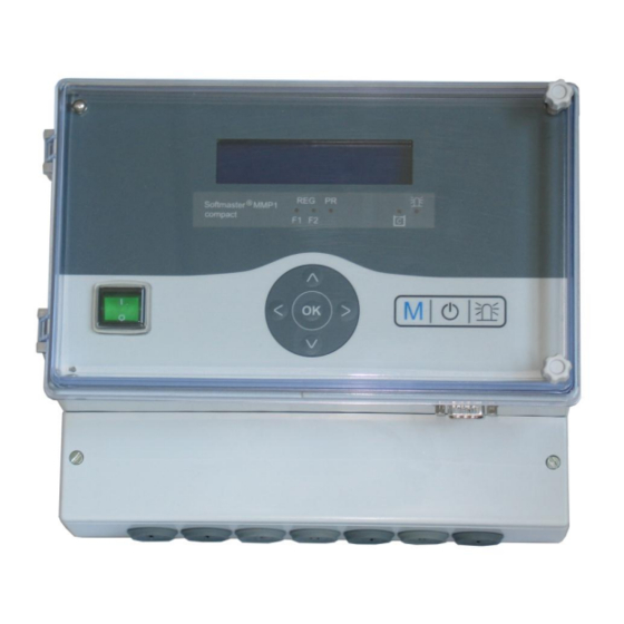
General description Views of the instrument Terminal box Serial interface RS232 Drilling-scheme 4/30... -
Page 5: Description Of Display And Operating Features
Description of display and operating features or current regeneration is stopped (depending on the type of A On/Off switch plant the filter starts to operate / is put into standby or Use this switch to switch the instrument on or off. reserve). -
Page 6: Led Displays
LED displays Filter 1 Filter 2 Add. Warning Error „Chemicals low“ prog. in regeneration The displays signal operating statuses, plant functions and current error messages: Reg. F1 and Reg. F2 (green) LED lights up: Filter 1 or Filter 2 in regeneration. LED flashes: Today, a regeneration of the respective filter is triggered at the set time (also see Regeneration delay). -
Page 7: Error Messages
Error messages In addition to the displayed error messages, the red LED ‟Alarm” lights up or flashes. Alternate display of all error messages and operating displays. Each occurred error is stored in the error history. Error message ‟Power failure” Message after each switching on, ‟power failure”. Check the time and, if Power failure necessary, set the time. - Page 8 Error message ‟Maximum number of regenerations achieved” The entered maximum number of possible regenerations has been achieved. Max. reg. nums. The current status of the regeneration meter can be viewed in the SERVICE menu under ‟Reg. meter”. In addition to the error message, the yellow warning light ‟Low chemicals” lights up. Confirm the fault display via the key.
-
Page 9: Terminal Block Identification
Terminal block identification Functions (IN = input, OUT = output) Function Terminal Type Note 6x mains protective earth Mains, N = Neutral Mains input Mains, L = Live 230 - 240 V AC 5x live, switched Mains voltage, max. 6 A 5x Neutral, switched Filter 1 - common Filter 1 - normally open... -
Page 10: Description Of The Relay Outputs
Description of the relay outputs Filter 1 / Filter 2 Pilot distributor or central control valves 1 and 2 Connect the regeneration valves (central control valves) or pilot distributors which are controlled via an electrical change- over switch or impulse switch control at these relay outputs (terminal 5, 6, 7, 8 and 5‘, 6‘, 7‘, 8‘). Change-over contact: For versions with a change-over switch the output changes after each regeneration stage. -
Page 11: Description Of The Signal Inputs
Description of the signal inputs Note Only connect the signal inputs "WM", "LL", "PROG", "START" and "STOP" to volt-free contacts! START External regeneration start Connection for hardness monitoring instrument (e.g. Testomat) Function Type of Contact Test time Action START – Filter change (only for double- programmable programmable Start of regeneration after... - Page 12 Low chemicals For extended control of the plant it is possible to use the "LL" input for connecting a level transmitter (monitoring of the chemical tank). Function Type of Contact Test time Action programmable: – Chemical fill valve open programmable Level transmitter input: –...
-
Page 13: Programming
Programming Menu start “M“ Use the "M" key to open the menu. Menu selection / Selection The current line position is displayed as a header in CAPITAL LETTERS. Use the "ENTER" key to activate the selected/displayed menu item, i.e. you ‟jump” into a submenu. -
Page 14: Switching On And Power Failure
After switching on the instrument and after each power failure, the plant automatically returns to the last active position. Operating modes (plant type) ® The Softmaster MMP 1 compact controller can control the following softening plants: Single-filter plant Only one filter is in operation. Soft water is not available during regeneration. -
Page 15: Hardness Unit
Hardness unit HARDNESS UNIT The raw water hardness can be entered and displayed in various units: German hardness = dH °dH French hardness = f (1.79 = 1° dH) ppm as CaCO = ppmCaCO (17.9 ppmCaCO , 1° dH) °f - ppmCaCO3 - The exchanger capacity has to be entered (in the next menu item) according to... -
Page 16: Regeneration Delay
Quality-controlled regeneration ® With the internal control function combined with a water hardness measuring instrument (e.g. Testomat 2000 / ECO) it is possible to install a convenient and reliable plant. The water hardness measuring instrument monitors the soft water hardness and sends a start signal to the controller to trigger regeneration once the set limit value has been reached. By combining the various control possibilities you can ensure the largest possible operational reliability. -
Page 17: Regeneration Interval
Regeneration interval To prevent improper bacterial contamination of the resin bed during longer downtimes, REG. INTERVAL regeneration can be carried out at fixed daily intervals. The regeneration interval (0 - 99 days) complies with the operational conditions and Days national regulations for the drinking water supply (e.g. DVGW, DIN, etc.). If regeneration should be carried out at a certain time, please additionally program ‟Regeneration delay”... -
Page 18: Fct.out Al/Pr
Fct. Out AL/PR FCT.OUT AL/PR The output AL/PR can either be used as alarm output or as output for the additional Aux. prog. PR program PR. Alarm AL Additional program PR If under menu „FCT.OUT AL/PR” the function „Aux prog. PR” is selected, the output AUX PROG. -
Page 19: Function Start Input
Function START input FUNCT. START If regeneration should be triggered quality-dependently, a water hardness measuring norm. closed - instrument has to monitor the soft water hardness. If the set limit value has been reached, the measuring instrument sends a start signal to the controller for triggering ... -
Page 20: Service" Menu
“SERVICE” menu Request and change current settings and statuses of the instrument in the service menu. Regeneration of the reserve filter REG. RES.FILTER If the reserve/standby filter should be regenerated, press the ‟ENTER” key in the menu. START (Enter) No filter change occurs. This function is only possible with double-filter operation! ONLY FILT.CHANGE Filter change without regeneration start... -
Page 21: Water Meter
Water meter WATER METER The water meter records the removed soft water quantity for the quantity-dependent regeneration triggering and the total quantity counted since the last reset. Soft water0.0m Reset (ENTER): Resets of the currently stored total soft water quantity. Total 0.0m Fast mode... -
Page 22: Status History
Status history STATUS HISTORY Open the status history via ‟display”. The status history is a list of statuses which have occurred during current operation. display The occurred status is recorded with time and date, e.g.: A. Reg F1: 23.7m delete 21:28 30.09.03 A maximum of 20 statuses is logged in a ring buffer. -
Page 23: Menu Structure
Menu structure Call the basic factory default setting by simultaneously pressing and holding down the ‟Arrow down‟ key while switching on the instrument. The most recent programming will be lost! 23/30... -
Page 24: Technical Appendix
Technical Appendix Connection example for control valves (415, 426, 427, 441) from WWWS 24/30... -
Page 25: Connection Example For Control Valve Autotrol 952
Connection example for control valve Autotrol 952 Filter1 Filter2 Sync BV2 AL /PR schwarz Einstellungen am Sof tmaster MMP settings of Softmaster MMP Ventilansteuerung: 3 Min. Impuls valve type: 3 min. impulse weiß = white Homing switch rot = red schwarz = black... -
Page 26: Connection Example For Control Valve Fleck2900 (Double-Filter Plant)
Filter2 AL/PR ro t schwar z E instellungen am Softm aster M MP V entilansteuerung: W echsler settings of Softmaster MMP R eg. Schritte : 4 valve type: change-over reg. stages: 4 Als Betriebsventil wird ein Magnetventil eingesetzt Homi ng swi tch... -
Page 27: Connection Example For Control Valve Fleck9000 (Single-Filter Plant)
Softmaster MMP valve type: change-over E instellungen am Softmaster M MP reg. stages: 4 V entilansteuerung : W echsler R eg- Schritte : 4 A solenoid valve is installed as Als Betriebsventile werden operating valve. - Page 28 Connection example for control valve Fleck9000 (single-filter plant) valve design: without timer, for connection of external control Filter1 Filter2 AL/PR settings of Softmaster MMP valve control: change-over ro t reg. stages: 4 schwar z E instellungen am Softm aster M MP blau = blue...
-
Page 29: Conformity Declaration
Conformity Declaration 29/30... -
Page 30: Technical Data
Technical data Power supply: 230 - 240 V or 24 V or 115V+/-10% / 50 -60 Hz Power consumption without exterior load: max. 9 VA Degree of protection: IP54 Protection class: Conformity: EN 61000-6-2, EN 61000-6-4, EN 61010-1 Ambient temperature: 0 - 45C Housing dimensions: W x H x D = approx.
Need help?
Do you have a question about the MMP compact and is the answer not in the manual?
Questions and answers