
Related Manuals for HST HST-HP201-2


Summary of Contents for HST HST-HP201-2
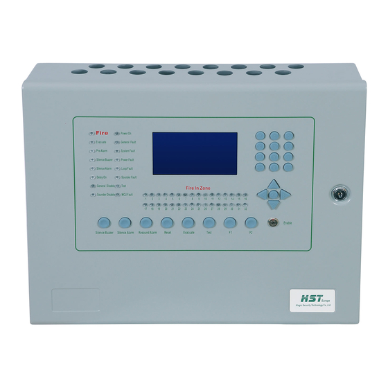
- Page 1 HLogic Security Technology Addressable Fire Alarm Control Panel HST-HP201-2 Product Manual August-2015 UMPL-101 R 1.00...
-
Page 2: Table Of Contents
Contents Introduction ......................4 Features & specifications ................... 4 Components ....................... 5 3.1. Power circuits ....................5 3.2. Input & output circuits .................. 6 3.2.1. Loop detectors ..................6 3.2.2. Dry contacts ..................7 3.2.3. Sounders ..................... 7 3.2.4. Relays ....................8 3.2.5. - Page 3 Appendixes ...................... 44 7.1. Appendix A: Panel Default Values ............. 44 August-2015 Page 3...
-
Page 4: Introduction
HST addressable devices per loop. With its extra large graphical display, it configures almost all panel settings via its very simple interface or with it’s built in PC interface via HST RINGER configuration software. It stores almost all different actions monitored up to 4000 event log records. -
Page 5: Components
3. Components 3.1. Power circuits HST-HP201-2 contains a switched mode power supply module producing 27VDC from 230VAC/50Hz main input source. Main panel board is protected with 5A/20 mm fast response glass fuse located at the lower right side of the board. Care must be taken when changing this fuse in case of failure. -
Page 6: Input & Output Circuits
3.2. Input & output circuits 3.2.1. Loop detectors HST-HP201-2 contains 2 class A detection loop circuits. Each loop can hold up to 250 addressable loop devices. Loop output devices (Sounders, Modules,…) should not exceed 64 devices per loop and remaining could be input devices (Detectors, Call points,…). Loop communication protocol is HST protocol. -
Page 7: Dry Contacts
3.2.2. Dry contacts HST-HP201-2 contains 3 dry contact remote inputs. Triggering of any input is done by connecting 0V terminal beside input terminal with the selected input. Input signal is latched until fire reset. After fire reset if remote input is still connected to 0V terminal, programmed action will be active again. -
Page 8: Relays
3.2.4. Relays HST-HP201-2 contains 3 form C dry contact relays. All relays are rated 2A @ 30VDC. By default relay 1 & 3 trigger on any fire or manual evacuate conditions while relay 2 triggers on any fault conditions. Different configuration can be done from panel configuration menus or from computer software. -
Page 9: Fire Function Keys
3.3.6. Test key HST-HP201-2 contains one Test key which is used to start LCD & LEDs test for 2 seconds. LCD will draw HST Logo and all Icons in an inverted way and all LEDs will be turned on. August-2015... -
Page 10: Enable Key
3.3.7. Enable key HST-HP201-2 contains one enable key which must be turned on before saving any panel settings. Icon is shown on LCD when enable key is on. Enable key should be normally turned off to secure panel data from unauthorized changes. -
Page 11: Buzzer
Zone 1…32: Each LED Indicates the presence of at least one fire condition in its zone 3.4.3. Buzzer HST-HP201-2 contains a buzzer which sounds at any fire or fault condition. It can be silenced manually by pressing Silence Buzzer key at access level 1. It stops sounding automatically in case of fire reset or in case of all fault conditions have been restored. -
Page 12: Installation
4. Installation Before working with panel mounting, wrist strap must be used to discharge any static charges to the ground from human body to protect board electronic sensitive elements. Input power terminals and battery terminals must be completely disconnected. As shown from panel case drawing, it contains 3 holes for mounting. Panel contains sufficient place to mount the case without removing the main board. -
Page 13: Panel Operation
HST-HP201-2 will not power on if backup batteries is the only power source connected. Panel must be powered on with its main power. After power on, power LED is on and LCD displays HST logo while panel is initializing its hardware modules and it’s saved data. -
Page 14: Access Levels
LCD. 5.1. Access levels HST-HP201-2 has 3 access levels for different panel operations from panel users. Access level 1 is the least secure level and has no protected password. It is the default level after power on and it has the ability to see different fire and fault information at the main screen and it can silence panel buzzer. -
Page 15: Panel States
5.2. Panel states HST-HP201-2 has 7 different panel states. Init & Stop state: This panel mode is valid at power up while panel is intializing its modules and when panel is doing restore for all its default data. Any fire or fault conditions will happen in this phase will be ingnored by the panel. -
Page 16: Lcd Icons
Evacuate conditions always override any fault conditions. 5.3. LCD icons HST-HP201-2 has 8 different LCD icons used to show some information about panel operation. It is ordered from left to right of the screen. ... -
Page 17: Working With Main Screen
Silence alarm: Icon is displayes when active alarms are manually silenced. 5.4. Working with main screen HST-HP201-2 main screen is the default LCD screen that shows all fire & fault related conditions information. Current system status is displayed at the left. By default, status is normal which means that no fire or fault conditions are present at the panel. - Page 18 There are 2 numbers at the right of the screen displayed when there are active conditions. The left number is number of conditions in the current selected tab (fire, fault or evacuate). The right number is total number of fire, fault and evacuate condition in the whole panel. For example if the panel detects 7 fire conditions and 9 fault conditions and 2 manual evacuate conditions, So when fire tab is selected the numbers will be 007/018.
- Page 19 List menu contains only type of the condition and name of the module. To show all information of the selected condition, press ENTER key. Detailed information is displayed. First line contains type of the condition (fire, fault or evacuate), ID of the condition and total number of conditions with same type.
- Page 20 Power faults, loop faults and onboard sounder faults have no records in fault tab. It is only displayed as icons at the last row of the LCD. Icon is removed automatically when fault is restored. For loop faults and sounder faults, LCD icon will not contain which loop or sounder has the fault.
-
Page 21: Programming
1. Access level icon on LCD will be cleared. 6. Programming HST-HP201-2 can be programmed from its onboard keypad or from PC via its RS232 interface. All features can be done from onboard keypad. August-2015... -
Page 22: Onboard Programming
6.1. Onboard programming To enter main configuration menu, press MENU key. If panel is at level 1 access, enter level 2 password from the numeric keypad and press ENTER key. If panel is at level 2 access or level 3 access, pressing MENU key is enough to go to main configuration menu. Pressing EXIT key will go to the main window with the last access level used. - Page 23 1. Set date To select this item use arrow keys to highlight it and press ENTER key or press 1 key from numeric keypad. This menu is used to update panel date. Enter new date using numeric keypad with format DD/MM/YY.
- Page 24 Panel time is preserved within the panel in case of onboard coin battery is mounted in its place in the main board even if the main power supply terminals and the backup batteries are removed. Panel time will be lost if coin battery is removed and will return to the initial panel time 12:00 AM.
- Page 25 This menu is used to change panel name which is displayed at the main window. Current panel name will be displayed on the screen. Press 0 key to show on screen keyboard. Current Panel name will be removed from the screen. Use arrow keys to move between letters. Press ENTER key to select the highlighted letter.
- Page 26 panel is at level 1 or level 2 access states, panel will display level 3 access password window. Enter the 4 level 3 password digits and press ENTER key. 6. Events status To select this item use arrow keys to highlight it and press ENTER key or press 6 key from numeric keypad.
-
Page 27: Menu2: On Board Configuration
6.1.1.2. Menu2: On board configuration This menus consists of 5 menu items 1. Relays configuration To select this item use arrow keys to highlight it and press ENTER key or press 1 key from numeric keypad. This menu is used to configure all panel onboard relays. You can select any relay using arrow key and press ENTER key on the highlighted key or press the key number directly from numeric keypad. - Page 28 X Icon in front of a relay means that this relay is in disabled state. After selecting one relay, relay configuration window appears with its last saved parameter value. First configuration is relay name. It is only used for relay identification and will not be shown on the display.
- Page 29 one of its selected events is active. Maximum value is 14 which mean that maximum delay is 7 minutes. To change the delay value, highlight it with arrow keys and directly enter the new delay value. A new small window appears beside the last delay value. Press ENTER key after entering the new delay value.
- Page 30 First configuration is sounder line name. It is only used for sounder line identification and will not be shown on the display. To change it, highlight it will arrow keys and press 0 key. On screen keyboard will be shown at the top right corner of the display. Working with it is exactly same as described in changing panel name section.
- Page 31 3. Auxiliary power configuration Programmable power outputs are not featured within this panel model. 4. Inputs configuration To select this item use arrow keys to highlight it and press ENTER key or press 4 key from numeric keypad. This menu is used to configure all panel onboard dry inputs. You can select any dry input using arrow key and press ENTER key on the highlighted key or press the key number directly from numeric keypad.
- Page 32 Second configuration is which event this dry input will trigger. There are 7 fixed events, ‘Fire’, ‘Fault, ‘Evacuate’, ‘Pre Alarm’, ‘Silence Alarm’, ‘Re-Sound Alarm’ and ‘Reset’. To select an event highlight the events field with the arrow keys and press 0 key to select one event.
- Page 33 X Icon in front of a function key means that this function key is in disabled state. After selecting one function key, function keys configuration window appears with its last saved parameter value. First configuration is function key name. It will be displayed on the main screen when this function key is pressed.
-
Page 34: Menu3: Loops Configuration
6.1.1.3. Menu3: Loops configuration This menus consists of 6 menu items 1. Loops status To select this item use arrow keys to highlight it and press ENTER key or press 1 key from numeric keypad. This menu is used to display information about loops status and number of devices connected to it. - Page 35 2. Loops configuration To select this item use arrow keys to highlight it and press ENTER key or press 2 key from numeric keypad. This menu is used to configure all panel onboard loops. You can select any loop using arrow key and press ENTER key on the highlighted key or press the key number directly from numeric keypad.
- Page 36 after saving, general disabled LED will be on. After saving, if loop status is changed from disabled to enabled. It will still be temporarily not working till auto learn is done. If loop status is changed from enabled to disabled, loop scan will be directly stopped. Number of identified derives is shown on the right After finishing updates of configuration, enable key must be on to save the new values.
- Page 37 After selecting one device, device configuration window appears with its last saved parameter value. Device type is shown near to bottom right section of the configuration window. First configuration is device name. For input devices, it will be displayed on the main screen when this device activates.
- Page 38 Sixth configuration is delay value. For input devices, it is fixed to 0 which mean device will trigger immediately when activated. For output devices, it is used to postpone the device activation to a defined amount. The number represents number of half minutes of delay. For example, if value is 3, so the delay value is 1.5 minutes.
- Page 39 ENTER key. If entered number is not within panel zones range, errors message appears. You can enter directly a correct number. Press EXIT key to cancel the complete operation. After entering zone number, zone configuration window appears with its last saved parameter value.
- Page 40 5. Disabled nodes To select this item use arrow keys to highlight it and press ENTER key or press 5 key from numeric keypad. This menu is used to show disabled loop devices. Disabled devices ID are written in a table format.
-
Page 41: Menu4: Advanced Configuration
6.1.1.4. Menu4: Advanced configuration This menus consists of 4 menu items 1. Auto learn To select this item use arrow keys to highlight it and press ENTER key or press 1 key from numeric keypad. This menu is used to scan all panel enabled loops and save all connected devices with its default settings. - Page 42 2. Level 3 password To select this item use arrow keys to highlight it and press ENTER key or press 2 key from numeric keypad. This menu is used to change level 3 access password. Enter new 4 digits password. Password must be entered twice for configuration.
- Page 43 settings. Panel will start to restore all its data and when finished it will display reset complete message on the display. Panel will wait 5 seconds and then it will restart itself. August-2015 Page 43...
- Page 44 7. Appendixes 7.1. Appendix A: Panel Default Values Configuration Item Configuration Default Value Panel name MAIN PANEL 1 Level 2 password 1234 Level 3 password 9876 GC1: Resound on 2 fire in same zone Not selected GC2: Bypass output delay in 2 fire Not selected Number of saved log events...
- Page 45 Zone: 1 Actions: Fire, Evacuate Silence state: Selected Output loop devices Zone: 1 Output Delay: 0 August-2015 Page 45...
Need help?
Do you have a question about the HST-HP201-2 and is the answer not in the manual?
Questions and answers