
Related Manuals for HST HP101


Summary of Contents for HST HP101
- Page 1 HP101 Fire Alarm Control Panel 4-16 Zones User & Installation Manual IMPORTANT This manual should be left with the panel after installation. We reserve the right to change product specifications without prior notice.
-
Page 2: Table Of Contents
Copyright © Products 2014 Index 1. INTRODUCTION......................3 .....................3 RODUCT EATURES ................3 LECTRICAL PECIFICATIONS ..............4 LARM YSTEM IMITATIONS ................6 NSTALLATION RECAUTIONS 2.CONTROL PANEL INSTALLATION................7 2.1 I ....................7 MPORTANT OTICE 2.2 M ...................8 OUNTING NCLOSURE 2.3 AC P ..................9 OWER ONNECTION 2.4 B ...................9 ATTERY NSTALLATION... -
Page 3: Introduction
1. Introduction The fire alarm control panels (4 Zones, 8 Zones, and 16 Zones) provide all of the sophisticated features required of a leading edge conventional fire alarm system along with the simple operation and efficient installation methods demanded by both installers and building users. -
Page 4: Fire Alarm System Limitations
Notification Appliance Circuits(Sounder) 2 NACs, Special Application Maximum NAC Current Rating 1 Amp maximum per circuit NAC End-of-line Resistor 10K ohms 1/2W 5% FAULT Relay rating 2A & 30VAC, resistive Alarm( Auxiliary ) Relay rating 2A & 30VAC, resistive 1.3 Fire Alarm System Limitations An automatic fire alarm system –... - Page 5 better than smoldering fires. Because fires develop in different ways and are often unpredictable in their growth, both types of detectors are necessarily best and a given type of detector may not provide adequate warning of a fire. A smoke detector cannot be expected to provide adequate warning of fires caused by arson, children playing with matches (especially in bedrooms), smoking in bed, and violent explosions (caused by escaping gas, improper storage of flammable materials, etc.).
-
Page 6: Installation Precautions
protection against telephone line failure, backup radio transmission systems are recommended. The most common cause of fire alarm malfunction is insufficient maintenance. To keep the entire fire alarm system in excellent working order, ongoing maintenance is required as the manufacturer’s recommendations, and UL and NFPA 72 shall be followed. -
Page 7: Control Panel Installation
damaged when subjected to lightning induced transients. Although no system is completely immune from lightning transients and interferences, proper grounding will reduce susceptibility. Overhead or out-side aerial wiring is not recommended, due to an increased susceptibility to nearby lightning strikes. Consult with the Technical Services Department if any problems are anticipated or encountered. -
Page 8: Mounting The Enclosure
DO NOT alter any mechanical or electrical features of the equipment supplied BE FAMILIAR with the building code, fire prevention code, and/or requirements of the Authority Having Jurisdiction (AHJ) in the locale of the installation. ! Caution ! Under normal and fault conditions, AC line voltages may be present on any terminal. Touching any component could be hazardous and result in loss of life. -
Page 9: Ac Power Connection
Figure 2.1 - The dimensions of mounting enclosure 2.3 AC Power Connection WARNING! To reduce the risk of electrical shock, make sure that all power has been turned off or disconnected prior to attempting to connect AC power to the Power Supply. Apply the AC Power BEFORE connecting the batteries to the Panel! Provide the Fire Alarm Control Panel with a dedicated AC Circuit rated 10 Amps or higher. -
Page 10: Zone Installation
Figure 2.3 - Batteries wiring connection 2.5 Zone Installation The panel has either 4, 8 or 16 class B conventional input zones. Wire the smoke, heat or multi detector positive terminals to the terminal labeled “+” and the negative detector terminals to the terminal labeled “-“ as shown in figure 2.4 which shows the panel. -
Page 11: Ringing The Alarms Remotely
AUXILIARY FAULT CONTACTS C NC NO C NC NO C NC NO Figure 2.6 –Realy outputs 2.8 Ringing The Alarms Remotely The class change (CC) facility allows a remote source to sound the alarms. When the CC terminal is connected to the ‘Perm 28V -’ terminal, the alarms will sound. Class Change (CC) Remote C/NO contacts... -
Page 12: Connect To Repeater
2.10 Connect To Repeater There is one jump JP1 on the repeater PCB board. For each one fire alarm control panel can connect 64 repeaters in the same RS485 communication wires. The default setting for RS485 JP1 jump is set to position 2, which EOF of RS485 is zero ohm. -
Page 13: Inner Door Label (Wiring Diagram)
2.12 Inner Door Label (Wiring Diagram) Z o n e s 9 - 1 6 P C B B o a r d ( o p t i o n a l ) Z o n e s 9 - 1 6 I n p u t E O L R e s i s t o r 4 . -
Page 14: Control Panel Operation
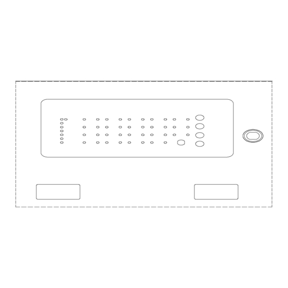
3. Control Panel Operation Enabling the front panel buttons. To enable the front panel buttons, the key switch in the top left of the panel must be turned to the ‘On’ position and the Key Enable Led will be lit. Performing a lamp test. -
Page 15: Led Indicators
Once the required zones have been selected, press the ACK button (Silence alarm button ). If any zones were disabled, the disable LED and the relevant zone disable LED(s) will remain lit. All incoming signals from disabled sense zones will be ignored. -
Page 16: Fault Finding
The alarm panel's sounder will activate if a trouble condition exists. In a trouble condition, the panel displays the zone or devices causing the trouble condition. The trouble indicator goes out automatically when the situation causing the trouble condition is rectified or restores to normal. 5.Fault Finding Front panel buttons not working. -
Page 17: Note
Ensure batteries are connected correctly and battery leads are secure. Note: Date Date Time Zone Event Action Required Initials Completed - 17 -...
Need help?
Do you have a question about the HP101 and is the answer not in the manual?
Questions and answers