
Related Manuals for Sawo Glass Front

Summary of Contents for Sawo Glass Front
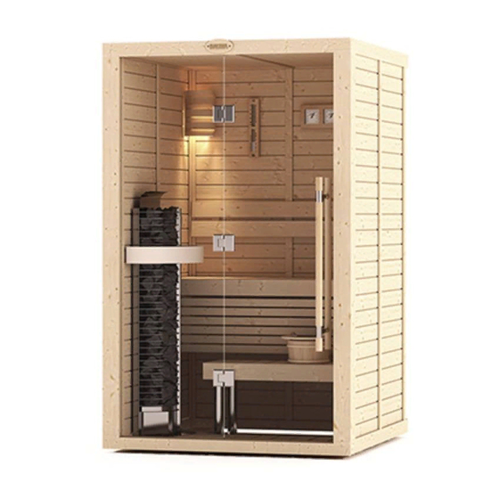
- Page 1 MANUAL Glass Front Sauna Room Assembly Classic Bench Version: 1.3 Note: Above images are for illustrative reference only and may differ from actual item.
- Page 2 Parts List Exterior *For room with full glass wall Ceiling Assembly Wall Elements Exterior Mouldings Top Exterior Mouldings Bottom Exterior Mouldings Main Base Frame Bolt Leveler Door Set Glass Wall (no holes) 10. Glass Window (with holes for hinges) 11. Front Outer L Mouldings 12.
- Page 3 Screws for Room Exterior 6RM08-123 Vertical Moulding 42mm thick Bolt Leveler Twist to adjust height 6RM08-109 6RM08-123 L Molding Screw Horizontal Moulding 75mm wide Screws for Room Interior 6RM17-002 Cam Lock Bolt 6RM08-123 Corner Moulding 6RM08-036 Back Rest 4SR35-002 Screw Cap for Back Rest 6RM08-125 Upper and Lower Bench Frame 6RM08-032...
-
Page 4: Wall Assembly
Wall Assembly Frames, Cam Lock Connect base frames according to their corresponding numbers. Leveler 6RM08-036 Screw No. 1 is underneath the glass walls and door and numbers increase clockwise Use a Leveler to make the frame level to the floor Twist BOLT to adjust height Do not seal the gap underneath the base frame. - Page 5 Wall Assembly Wall Attachments and Sequence Attach wall panels from the first corner (for easy installation). Take note of the grooves direction (groove facing left). Start from this corner Wall 3 Wall4 Wall5 Wall 3 Wall 4 Wall2 Wall6 Tongue and groove Wall 2 Wall1 Wall7...
- Page 6 Ceiling Assembly Attach Ceiling Assembly via tongue to Groove. Ceiling to ceiling connection side view Interior ceiling moulding 6RM08-123 Vertical Moulding 42mm thick Check that the ventilation hole is in the right position (refer to plan drawing for ventilation location) Attach all mouldings except “Front top/bottom outermost molding and Outer L mouldings”...
- Page 7 Interior Furnishes Assembly 1420ML Sauna Room Attach Bench Support at suggested Attach back rest to wall, attach leg height with screws,then place over the support to bench frame. Bench Frame Assembly and screw to wall. 6RM08-125 Upper and Lower Bench Support 6RM08-036 Screw Screw Cap...
- Page 8 Interior Furnishes Assembly 1414 LS/RS Sauna Room Attach bench support at designated Attach back rest to wall then attach leg height (reference markers on the wall). support to bench frame before attaching the frames to the wall. 6RM08-125 Upper and Lower Bench Support 6RM08-036 Screw Height dimensions should be taken in reference to the...
- Page 9 Interior Furnishes Assembly 2020 ML Sauna Room Attach bench support at designated Attach back rest to wall, attach leg support height (reference markers on the wall). to bench frame before attaching the bench support frames to the wall. 6RM08-125 Upper and Lower Bench Support 6RM08-036 Screw Screw Cap...
- Page 10 Glass Wall Assembly Glass Hinge components Faceplate Front L Plastic gaskets Plastic shield Plastic divider Faceplate Front L Hexagonal Screw Faceplate Back R Plastic Bushings Faceplate Front R Annoying sounds can be heard from improper Allen Wrench hinge assembly, ensure correct assembly along with the plastic spacers.
- Page 11 Glass Wall Assembly Glass Door Installation and Alignment Attach the Faceplate Front R to the glass wall and secure with Faceplate Back R with screws. Faceplate Front R Faceplate Back R Glass Wall from inside. Install from the inside. Loosely install the glass door then secure with Faceplate Back R. Faceplate Back L Glass Door from inside.
- Page 12 Glass Wall Assembly Glass Door Installation and Alignment Make and insert a 3mm thick wooden spacers underneath the glass door as well as the sides of the door (see illustration below). Then tighten the door hinges screws when glass door has even spacing all around.
- Page 13 Glass Wall Assembly Glass Door Installation and Alignment Attached remaining Front outer L Moulding. Refer to door handle assembly manual. 6RM08-109 L Molding Screw After the installation and there is still uneven gaps on glass door, align it by rotating the abs Tips bolt leveler until the glass wall swings freely.
- Page 14 Glass Wall Assembly (1414 LS/RS) Attach the glass wall where the glass Secure the glass wall with solid molding frames ridges are located. with a screw and insert top/bottom glass filler. Glass fi ller fi lls the small gap on top and below the glass door.
-
Page 15: Electrical Layout
Electrical Layout Electrical / Wiring Locations Conduits are on both sides for light, controls and heater. Conduit Sauna Light Ventilation Junction Box Heater & Sensor Conduit Conduit TOP VIEW Light Switch / Heater Control Electrical Conduit Locations: For heater and regulating sensor For sauna light switch and heater control For sauna light Wire Installation:... - Page 16 Electrical Layout Separate Control Installation (NS model heaters only) A conduit pipe is provided for the Conduit to control unit control unit. Conduit location If wanting to fl ush the control unit into the wall, cut a hole according to your control unit’s specifi cations.
Need help?
Do you have a question about the Glass Front and is the answer not in the manual?
Questions and answers