Sign In
Upload
Download
Table of Contents
Contents
Add to my manuals
Delete from my manuals
Share
URL of this page:
HTML Link:
Bookmark this page
Add
Manual will be automatically added to "My Manuals"
Print this page
×
Bookmark added
×
Added to my manuals
Manuals
Brands
Circutor Manuals
Test Equipment
MEG-1000
Instruction manual
Circutor MEG-1000 Instruction Manual
Insulation guard
Hide thumbs
1
2
3
4
5
6
7
8
9
10
11
12
13
14
15
16
17
Table Of Contents
18
page
of
18
Go
/
18
Contents
Table of Contents
Bookmarks
Table of Contents
Basic Instructions
Main Characteristics
Installation and Start-Up
Installation
Operation Mode
Safety Considerations
Maintenance
Advertisement
Quick Links
1
Installation and Start-Up
Download this manual
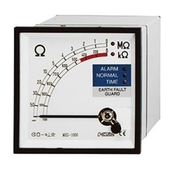
INSULATION GUARD
MEG-1000
(Code M15051)
INSTRUCTION MANUAL
(M98122001-20-19A)
CIRCUTOR S.A.
(c)
Table of
Contents
Previous
Page
Next
Page
1
2
3
4
5
Advertisement
Table of Contents
Need help?
Do you have a question about the MEG-1000 and is the answer not in the manual?
Ask a question
Questions and answers
Related Manuals for Circutor MEG-1000
Test Equipment Circutor Mi5500e User Manual
Electronic insulation tester (37 pages)
Test Equipment Circutor MPC-20 Instruction Manual
Step and touch voltage tester. ground resistance tester (30 pages)
Test Equipment Circutor MD5060e User Manual
Digital insulation tester (69 pages)
Test Equipment Circutor M15051 Instruction Manual
Insulation guard (18 pages)
Test Equipment Circutor TL-6e User Manual
Digital earth tester (57 pages)
Test Equipment Circutor OT-60 Instruction Manual
Dielectric strength tester for isolating oils (16 pages)
Test Equipment Circutor CR-250 Instruction Manual
Current injection relay tester (10 pages)
This manual is also suitable for:
M15051
Table of Contents
Print
Rename the bookmark
Delete bookmark?
Delete from my manuals?
Login
Sign In
OR
Sign in with Facebook
Sign in with Google
Upload manual
Upload from disk
Upload from URL


Need help?
Do you have a question about the MEG-1000 and is the answer not in the manual?
Questions and answers