
Related Manuals for Trig Avionics TT26


Summary of Contents for Trig Avionics TT26
- Page 1 TT26 ADS-B Transponder Installation Manual 01633-00-AC 24 January 2017 Trig Avionics Limited Heriot Watt Research Park Riccarton, Edinburgh EH14 4AP Scotland, UK Copyright Trig Avionics Limited, 2016...
- Page 2 This page intentionally left blank...
-
Page 3: Table Of Contents
TT26 ADS-B Transponder Installation Manual 24 January 2017 01633-00 Issue AC CONTENTS PREFACE ....................4 ...................4 URPOSE ....................4 COPE ............4 HANGES FROM REVIOUS SSUE ............4 OCUMENT ROSS EFERENCES INTRODUCTION ..................5 TT26 D ................5 ESCRIPTION ..................5 NTERFACES 2.2.1 TT26 ADS-B Transponder Unit ..........5 TECHNICAL SPECIFICATIONS ............7... - Page 4 TT26 ADS-B Transponder Installation Manual 24 January 2017 01633-00 Issue AC TT26 T ......12 RANSPONDER LECTRICAL ONNECTIONS TT26 Interface – Pinout ............13 5.4.1 TT26 T ........14 RANSPONDER NTERFACE ETAILS 5.5.1 Power Input ................14 5.5.2 TMAP Control Port ..............14 5.5.3 Auxiliary RS-232 Interface .............15 5.5.4...
- Page 5 TT26 ADS-B Transponder Installation Manual 24 January 2017 01633-00 Issue AC ............20 NTERFACE ONFIGURATION 6.2.1 Altimetry Source ..............20 6.2.2 GPS Source ................21 POST INSTALLATION CHECKS ............22 CONTINUED AIRWORTHINESS ............23 LIMITED WARRANTY ..............24 ENVIRONMENTAL QUALIFICATION FORMS ......25 ADS-B COMPLIANCE ..............27 11.1 ADS-B P ..........27...
-
Page 6: Preface
This document applies to the installation of the TT26 ADS-B Transponder. At the publication date of this manual the software version identifier for the TT26 is 1.6 and the FPGA version identifier is 1.5. The software and FPGA versions are subject to change without notice. -
Page 7: Introduction
ED-14G. The TT26 has a nominal power output of 250 watts, and meets the power output requirements for Class 1. The TT26 has a built in WAAS GPS receiver which meets the requirements for DO-229D class Beta1, and provides a position source for ADS-B transmissions from the transponder. - Page 8 The TT26 operates on 11 to 33 volts DC. Controller Datalink A two wire data link is used to connect the TT26 and the controller. Depending on TT26 option, this interface can be provided over a half-duplex RS-485 interface (TMAP RS-485 bus) or a full duplex RS-232 interface (TMAP over RS-232).
-
Page 9: Technical Specifications
TT26 ADS-B Transponder Installation Manual 24 January 2017 01633-00 Issue AC 3. Technical Specifications 3.1 TT26 Transponder Unit (01629-00) Specification Characteristics Compliance ETSO C112e Class 1 Level 2els, ETSO C166b A2 Class B1S, ETSO C10b, ETSO C88b, ETSO C145c Class Beta 1... -
Page 10: Installation Approval
475 g (1.05 lbs) 3.2 Installation Approval The conditions and tests required for the TSO approval of the TT26 are minimum performance standards. It is the responsibility of those desiring to install this transponder on or within a specific type or class of aircraft to determine that the aircraft operating conditions are within the TSO standards. -
Page 11: Unit And Accessories Supplied
00734-00 Connector, coaxial SMA 01645-00 4.3 Required Items Additional items you will require, but which are not in the TT26 package, include: Antenna and fixing hardware. The TT26 is compatible with any transponder antenna approved to ETSO C74 or C112, and any GPS antenna approved to ETSO or TSO C190. - Page 12 TT26 ADS-B Transponder Installation Manual 24 January 2017 01633-00 Issue AC Fixings. To mount the transponder body directly using the tapped holes you will need three M4 bolts. ______________________ Trig Avionics Limited...
-
Page 13: Installation
Avoid sharp bends and placing the cables too near to the aircraft control cables. The TT26 transponder is mounted directly to the airframe using bolts into the three threaded holes in the chassis. Section 12 contains mounting point positions. -
Page 14: Cooling Requirements
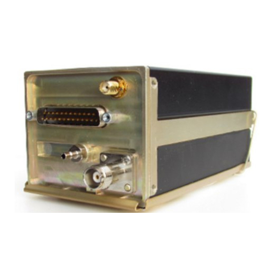
5.4 TT26 Transponder Electrical Connections The TT26 has a single 25 way male connector which provides the data and power inputs to the transponder. A single TNC coaxial connector attaches to the transponder antenna, and a single SMA connector attaches to the GPS antenna. -
Page 15: Tt26 Interface - Pinout
TT26 ADS-B Transponder Installation Manual 24 January 2017 01633-00 Issue AC 5.4.1 TT26 Interface – Pinout Signal Direction Ground TMAP1A Bidirectional TMAP1B Bidirectional Ground RS-232 Aux Input Ground RS-232 Aux Output TMAP2A Bidirectional TMAP2B Bidirectional Ground Auxiliary Power Output Ground... -
Page 16: Tt26 Transponder Interface Details
TT26 and a control system. The protocol is documented in DEV/TMAP/005 Enhanced TMAP Protocol Specification. Depending on configuration options the TT26 may be controlled by the TMAP RS-485 bus on pins 2, 3, 8 and 9, or by TMAP over RS-232 on pins 24 and 25. -
Page 17: Auxiliary Rs-232 Interface
B, both of which must be connected for communication to work. There are two sets of TMAP pins on the TT26, TMAP1 A and B, and TMAP2 A and B. This is to support future installation wiring options. The two sets are identical, and either pair (TMAP1 or TMAP2) may be used to connect to the control head;... -
Page 18: Squat Switch Input
5.6 D Connector Crimp Terminals The 25 way connector supplied with the TT26 installation kit are MIL standard versions of the popular sub miniature D type connector family, and use individual crimp terminals and a receptacle. The MIL specification for this family of connectors is MIL-C-24308. -
Page 19: Wiring Considerations
Sensor Systems Inc S67-1575-135 TSO-C190 S67-1575-145 TSO-C190 S67-1575-137 TSO-C190 5.9 GPS Antenna Cable A low loss cable terminating at the TT26 in an SMA connector is required. The recommended cable is RG400 or RG142. Total cable loss including ______________________ Trig Avionics Limited... -
Page 20: Transponder Antenna
A low loss cable terminating at the transponder in a TNC connector is required. The TT26 is designed to meet Class 1 requirements with an allowance of 2 dB for loss in the connectors and cable used to connect it to the antenna. -
Page 21: Installation Setup And Test
Issue AC 6. Installation Setup and Test The system controller uses the TMAP protocol to provide important system parameters to the TT26, including the Mode S address. The following items should be configured in the system controller. 6.1 Core Configuration Items 6.1.1 Aircraft Address... -
Page 22: Squat Switch Source
01633-00 Issue AC 6.1.5 Squat Switch Source The Squat switch input allows the TT26 to automatically switch between Airborne and Ground modes. If the squat switch input is not connected the “Ignore Squat Switch” option must be selected. 6.1.6 Aircraft Length and Width On the ground, ADS-B transmits encoded aircraft size information which is used by ATC to identify taxiing routes and potential conflicts. -
Page 23: Gps Source
TT26 ADS-B Transponder Installation Manual 24 January 2017 01633-00 Issue AC computer, or to receive the altimetry data over the link from the controller. In all three cases the altimetry data will be transmitted from the secondary data output (either RS232 or RS485, depending on which port is the control port). -
Page 24: Post Installation Checks
TT26 ADS-B Transponder Installation Manual 24 January 2017 01633-00 Issue AC 7. Post Installation Checks Post installation checks should be carried out in accordance with your certification requirements. These checks should include: Mode S interrogations to verify correct address programming. -
Page 25: Continued Airworthiness
01633-00 Issue AC 8. Continued Airworthiness Other than for periodic functional checks required by the regulations, the TT26 ADS-B transponder has been designed and manufactured to allow “on condition maintenance”. This means that there are no periodic service requirements necessary to maintain continued airworthiness, and no maintenance is required until the equipment does not properly perform its intended function. -
Page 26: Limited Warranty
Heriot Watt Research Park Riccarton, Currie, EH14 4AP Trig Avionics will not accept or pay for any charges for warranty work performed outside our factory without prior written consent. This warranty applies only to products in normal use. It does not apply to units... -
Page 27: Environmental Qualification Forms
TT26 ADS-B Transponder Installation Manual 24 January 2017 01633-00 Issue AC 10. Environmental Qualification Forms Nomenclature: TT26 ADS-B Transponder Part Number: 01629-00-(xx) ETSO: C112e, C166b, C10b, C88b, C145c Manufacturer: Trig Avionics Limited Address: Heriot Watt Research Park, Riccarton, Currie, Scotland,... - Page 28 TT26 ADS-B Transponder Installation Manual 24 January 2017 01633-00 Issue AC Crash Safety Equipment tested to Category B type 5 Vibration Aircraft zone 2; type 3, 4, 5 to category S level M, type 1 (Helicopters) to category U level G Equipment identified as Category X –...
-
Page 29: Ads-B Compliance
24 January 2017 01633-00 Issue AC 11. ADS-B Compliance TT26 ADS-B transponders include support for Extended Squitter ADS-B out. The TT26 is a DO-260B compliant broadcast participant. 11.1 ADS-B Parameters Supported The following table summarises the ADS-B parameters that are transmitted by the TT26. -
Page 30: Faa 91.227 Compliance
150 milliseconds. 11.2 FAA 91.227 Compliance A TT26 can form the basis of 14 CFR 91.227 compliant ADS-B installation. For installations seeking certification to 91.227 or other applicable standards, additional compliance information is available on request from Trig Avionics Limited. -
Page 31: Installation Drawings
TT26 ADS-B Transponder Installation Manual 24 January 2017 01633-00 Issue AC 12. Installation Drawings 12.1 Direct Chassis Mount All dimensions in millimetres ______________________ Trig Avionics Limited... -
Page 32: Connector Arrangement
TT26 ADS-B Transponder Installation Manual 24 January 2017 01633-00 Issue AC 12.2 Connector Arrangement GPS Antenna TT26 Interface Static Pressure Transponder Connection Antenna All dimensions in millimetres ______________________ Trig Avionics Limited... -
Page 33: Basic Interconnect Diagram
TT26 ADS-B Transponder Installation Manual 24 January 2017 01633-00 Issue AC 13. Basic Interconnect Diagram ______________________ Trig Avionics Limited Page 31... - Page 34 TT26 ADS-B Transponder Installation Manual 24 January 2017 01633-00 Issue AC This page intentionally left blank ______________________ Page 32 Trig Avionics Limited...
Need help?
Do you have a question about the TT26 and is the answer not in the manual?
Questions and answers