Table of Contents
Advertisement
Quick Links
Generic TT31 Minor Modification
21 February 2008
Document Control
Title:
Identifier:
Issue:
Issue Date:
Author:
Authority:
CCB Category:
File Name:
Printed on:
Generic TT31 Minor Modification
SUP/TT31/001
Issue 1.6
21 February 2008
Andy Davis
Martin Gray
2
SUP TT31 001 1.6 Generic TT31
Minor Mod.DOC
28/02/2008 16:05:00
Advertisement
Table of Contents

Summary of Contents for Trig Avionics TT31
- Page 1 21 February 2008 Document Control Generic TT31 Minor Modification Title: Identifier: SUP/TT31/001 Issue: Issue 1.6 Issue Date: 21 February 2008 Andy Davis Author: Authority: Martin Gray CCB Category: File Name: SUP TT31 001 1.6 Generic TT31 Minor Mod.DOC 28/02/2008 16:05:00 Printed on:...
-
Page 2: Table Of Contents
Generic TT31 Minor Modification 21 February 2008 SUP/TT31/001 Issue 1.6 CONTENTS PREFACE ............................1 ............................ 1 URPOSE ............................1 COPE ....................1 HANGES FROM REVIOUS SSUE ......................... 1 HANGES ORECAST ....................1 OCUMENT ROSS EFERENCES 1.5.1 Internal Documents ......................1 1.5.2... - Page 3 COMPLIANCE STATEMENT ....................12 THIS DOCUMENT IS CONFIDENTIAL AND CONTAINS COMMERCIALLY SENSITIVE INFORMATION TO TRIG AVIONICS LTD AND PARTNER COMPANIES. THE CONTENTS OF THIS DOCUMENT ARE TO BE KEPT CONFIDENTIAL AND ARE NOT TO BE DISCLOSED TO THIRD PARTIES WITHOUT THE PRIOR WRITTEN CONSENT OF TRIG AVIONICS LTD.
-
Page 4: Preface
Issue 1.6 1. Preface 1.1 Purpose To document the minor modification to replace a Mode A/C transponder with a Trig Avionics TT31 Mode S transponder. 1.2 Scope This minor modification applies to unpressurised single engine piston aeroplanes with fixed landing gear and 14 Volt or 28 Volt DC electrical systems, having an existing certified Mode A/C transponder installation, and an existing altitude encoder. - Page 5 Generic TT31 Minor Modification 21 February 2008 SUP/TT31/001 Issue 1.6 Direct Current Declaration of Design Performance EASA European Aviation Safety Agency ETSO European Technical Standards Order MOPS Minimum Operational Performance Standard Pilots Operating Handbook ______________________ Trig Avionics Limited Page 2...
-
Page 6: Introduction
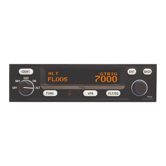
Issue 1.6 2. Introduction The TT31 Mode S panel mount transponder is an ED-73B Class 1 compliant Mode S level 2 datalink transponder, with support for extended squitter, which also meets the relevant environmental requirements of ED-14D. The TT31 meets the European requirements for Mode S Elementary Surveillance and is certified to ETSO 2C112b. -
Page 7: Modification Details
KT76A or KT78A, sliding it out of the tray, sliding in a TT31, and latching it into the tray. -
Page 8: Installed Equipment Suitability
The TT31 is certified by EASA to ETSO 2C112b under ETSOA EASA.21O.643. 3.4.2 Deviations A single deviation is noted on the DDP for the TT31 which affects the behaviour of the transponder when recovering from All-Call interrogations which have been locked out. This deviation has negligible effect on this installation. -
Page 9: Wiring Diagram
Generic TT31 Minor Modification 21 February 2008 SUP/TT31/001 Issue 1.6 significant capacity is on the DC bus at all times. Induced Signal Category A Equipment intended for operation where Susceptibility interference-free operation is desirable. RF Susceptibility Category T Specified in the HIRF rules; representative of the internal EMI environment from aircraft equipment. -
Page 10: Voltage Conversion In 28 Volt Aircraft
28 Volt aircraft with a KT76A it is good practice to replace the KT76A tray with a Trig TT31 tray, and install a connector – even if it is empty – in the TT31 tray secondary connector position. -
Page 11: Accomplishment Instructions
4.4.1 Verify Circuit Breaker Status Trace and identify the existing transponder circuit breaker. Verify that the circuit breaker is in satisfactory condition and is of the correct type and rating. The circuit breaker for the TT31 should rated between 3 Amps and 5 Amps. -
Page 12: Remove Existing Transponder
The voltage reduction typically uses a resistive dropper attached to the firewall or other metal aircraft structure. Remove or bypass the resistive dropper; the power supply to the TT31 must come directly from the 28V aircraft supply. -
Page 13: Non Kt76A Replacement
Pin N – the lower left pin when viewed from the front – is not normally used in a KT76A or KT78A installation and should be empty. Pin N is used for bench testing of the TT31 and MUST NOT be connected in the aircraft –... -
Page 14: Interference Effects
Generic TT31 Minor Modification 21 February 2008 SUP/TT31/001 Issue 1.6 Operate each of the controls and verify that each performs the intended function. 4.5.2 Interference Effects With the transponder powered on, operate each of the other electrically operated aircraft systems to determine that no significant interference effects are present. -
Page 15: Compliance Statement
Generic TT31 Minor Modification 21 February 2008 SUP/TT31/001 Issue 1.6 5. Compliance Statement CS 23 Requirement Compliance References Para 23.1301 (a) Installed equipment to be of a TT31 is approved under TT31 DDP. design appropriate to its ETSO 2c112b. Review of intended function. - Page 16 Capability Report, Pressure Altitude With the exception of Pressure Altitude all these and Flight Status (including for the avoidance of doubt, the Flight Status requirement) are provided directly by the TT31 transponder. Pressure Altitude compliance depends on the performance of the altitude encoder.
- Page 17 Gillham interface as required by EASA AD 2006-0265. Encoded altitude is displayed to the pilot by the TT31. Complete failure of the altitude source is flagged by the transponder. Erroneous indications can be identified by the pilot.
- Page 18 Generic TT31 Minor Modification 21 February 2008 SUP/TT31/001 Issue 1.6 periodic check of aircraft derived Testing detailed in Instructions for Continued data including 24-bit address or in the Airworthiness (see 3.3) requires testing, which includes event of a change of registration of 24-bit address and aircraft derived data, every 24 the aircraft.


Need help?
Do you have a question about the TT31 and is the answer not in the manual?
Questions and answers