Table of Contents
Advertisement
Quick Links
Advertisement
Table of Contents

Related Manuals for OPTIMUM Maschinen OPTIgrind GT 22


Summary of Contents for OPTIMUM Maschinen OPTIgrind GT 22
- Page 1 Operating Manual Version 1.0 Surface grinding machine Part no. 3111020...
-
Page 2: Table Of Contents
Table of contents Safety Glossary of symbols ............................6 Rating plate..............................6 Safety instructions (warning notes)........................ 7 1.3.1 Classification of hazards ........................7 1.3.2 Other pictograms..........................7 Intended use ..............................8 Reasonably foreseeable misuse........................8 1.5.1 Avoiding misuse ..........................9 Dangers that can be caused by the surface grinding machine.............. - Page 3 4.6.1 Switching the grinding wheel on .....................31 Switching the machine off ..........................31 Resetting an emergency stop condition .......................31 Mounting the grinding wheel ........................32 4.9.1 Mounting the grinding wheel on the flange ..................32 4.9.2 Balancing the grinding wheel......................33 4.10 Mounting the grinding wheel with flange on the spindle ................34 4.11 Selection of a grinding wheel ........................34 4.12...
- Page 4 9.6.1 Decommissioning........................... 77 9.6.2 Disposal of new device packaging ....................77 9.6.3 Disposal of the machine......................... 77 9.6.4 Disposal of electrical and electronic components ................77 9.6.5 Disposal of lubricants and coolants....................78 Disposal through municipal collection facilities.................... 78 Terminology/Glossary..........................79 Genauigkeitsbericht - Accuracy report......................
- Page 5 If you have any further questions after reading these operating instructions and you are not able to solve your problem with a help of these operating instructions, please contact your specialised dealer or directly the company OPTIMUM. Optimum Maschinen Germany GmbH Dr.- Robert - Pfleger - Str. 26 D-96103 Hallstadt...
-
Page 6: Safety
calls on you to act listings Rating plate DE Flächenschleifmaschine EN Surface grinding machine Optimum Maschinen FR Rectifi euse plane Germany GmbH Dr.-Robert-Pfl eger-Str. 26 ES Rectifi cadora GT 22 96103 Hallstadt / Deutschland IT Rettifi catrice... -
Page 7: Safety Instructions (Warning Notes)
Safety instructions (warning notes) 1.3.1 Classification of hazards We classify the safety warnings into different categories. The table below gives an overview of the classification of symbols (ideogram) and the warning signs for each specific danger and its (possible) consequences. Symbol Alarm expression Definition / consequence... -
Page 8: Intended Use
If the surface grinding machine is used in any way other than described above, modified without authorization of Optimum Maschinen Germany GmbH, then the surface grinding machine is being used improperly. We will not be held liable for any damages resulting from any operation which is not in accord- ance with the intended use. -
Page 9: Avoiding Misuse
Only metallic, cold and non-flammable materials may be machined with the surface grinding machine. In order to avoid misuse, it is necessary to read and understand the operating instructions before first commissioning. Operators must be duly qualified. 1.5.1 Avoiding misuse ... -
Page 10: Qualification Of Personnel
WARNING! The surface grinding machine may only be used with fully functional safety devices. Disconnect the surface grinding machine immediately, whenever you detect a failure in the safety devices or when they are not fitted! All additional parts of the machine which had been added by the customer need to be equipped with the prescribed safety devices. -
Page 11: Authorized Personnel
1.7.2 Authorized personnel INFORMATION Sufficient expertise is required for working on the surface grinding machine. Without the necessary training, nobody may work on the machine, even for a short time. WARNING! Inappropriate operation and maintenance of the surface grinding machine constitutes a danger for the personnel, objects and the environment. -
Page 12: Lockable Master Switch
WARNING! If you bypass, remove or override a safety device in any other way, you are endangering yourself and other persons working with the surface grinding machine. The possible consequences include: injuries due to tools, workpieces or fragments hereof which are flying off at high speed, ... -
Page 13: Prohibition, Warning And Mandatory Signs
speed, contact with rotating parts, fatal electrocution, pulling-in of clothes. If, in exceptional cases (e.g. electrical repairs), you briefly bypass a control device, you must constantly monitor the surface grinding machine during this time. 1.9.4 Prohibition, warning and mandatory signs INFORMATION All warning and mandatory signs must be legible. -
Page 14: Personal Protective Equipment
1.11 Personal protective equipment For certain work, personal protective equipment is required. Protect your face and your eyes: Wear a safety helmet with facial protection when performing work where your face and eyes are exposed to hazards. Wear protective gloves when handling pieces or tools with sharp edges. Wear safety shoes when you assemble, disassemble or transport heavy components. -
Page 15: Safety During Maintenance
Check if they are working properly! 1.15 Accident report Inform your supervisors and Optimum Maschinen Germany GmbH immediately in the event of accidents, possible sources of danger and any actions which almost led to an accident (near misses). There are many possible causes for "near misses". -
Page 16: Electronics
INFORMATION We draw your attention to specific hazards when carrying out work with and on the surface grinding machine in the description of this work. 1.16 Electronics Have the machine and/or the electric equipment checked regularly. Immediately eliminate all defects such as loose connections, defective wires, etc. A second person must be present during work on live components to disconnect the power in the event of an emergency. -
Page 17: Clamping Devices For Workpieces And Tools
1.18 Clamping devices for workpieces and tools ATTENTION! Attention when taking over existing clamping devices. Pleased thoroughly check that the clamping device is appropriate for your surface grinding machine. Only use clamping devices with a complete inherent rigidity. After collision damage, consult the manufacturer of the clamping device to obtain information on possible further use of the clamping device. -
Page 18: Technical Data
Technical data GT22 Surface grinding table length x width 200 x 450 mm T - slot size / number 14 mm / 1 Magnetic clamping plate 200 x 500 mm max. load grinding table including magnetic clamping plate 128 kg max. - Page 19 GT22 abrasive fluid 52 litres (coolant) Information Sound pressure level The specified numerical value represents the emission level and does not necessarily a safe working level. Although there is a correlation between the level of noise emission and the level of noise exposure, it cannot be used reliably to determine whether or not further protective measures are necessary.
-
Page 20: Delivery, Interdepartmental Transport, Assembly And Commissioning
Delivery, interdepartmental transport, assembly and commissioning Notes on transport, installation, commissioning Improper transport, installation and commissioning is liable to accidents and can cause damage or malfunctions to the machine for which we do not assume any liability or guarantee. Transport the scope of delivery secured against shifting or tilting with a sufficiently dimen- sioned industrial truck or a crane to the installation site. -
Page 21: Unpacking The Machine
Unpacking the machine INFORMATION The surface grinding machine is pre-assembled. The delivery takes place in several transport boxes. After unpacking and transport to the installation site, individual components of the sur- face grinding machine must be assembled and joined together. Install the machine close to its final position before unpacking. -
Page 22: Set-Up And Assembly
For lifting with a crane, first mount the transport bolts on the base of the machine. Then attach the steel cables to the bolts and hook. Pay particular attention when transporting with a crane: Raise the machine at the lowest possible speed. ... - Page 23 Design the working area around the surface grinding machine according to the local safety reg- ulations. The work area for operation, maintenance and repair must not be restrictive. INFORMATION In order to achieve high levels of functionality and machining accuracy, as well as a long ser- vice life of the machine, the set-up location should meet certain criteria.
-
Page 24: Installation Plan
Installation plan Floor space [mm] 1970 1400 Coolant tank 3.5.1 Anchored mounting Ground Concrete 3-150x150 Anchor bolts, flat steels and set screws are not included in the delivery. GT22 Translation of original operating instruction Version 1.0 - 2020-12-10... -
Page 25: Free Mounting
ATTENTION! Insufficient stiffness of the foundation leads to superimposition of vibrations between the surface grinding machine and the foundation (resonant frequency of the components). Critical oscillations during oscillating movements of the grinding table are reached very quickly if the overall system is not sufficiently rigid and lead to poor grinding results. -
Page 26: Cleaning The Machine
The surface grinding machine was painted with a one-component lacquer. Take this criterion into account when selecting your cooling lubricant. Optimum Maschinen Germany GmbH does not accept any guarantee for consequential dam- age caused by unsuitable process abrasives. The flashpoint of the emulsion must be higher than 140°C. -
Page 27: Electrical Connection
Fill the container of the coolant circuit with your process abrasive. The total filling quantity in the circuit must not exceed the height of the sedimentation tank for the grinding sludge. Connect the coolant return hose to the surface grinding machine and feed it into the cool- ant tank. -
Page 28: Operation
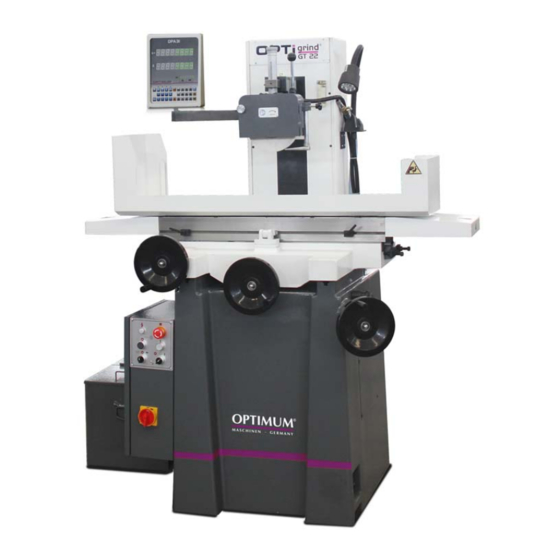
Operation Control and indicating elements Item Designation Item Designation Coolant line Work lamp Stop for oscillation travel Table carrier ( saddle ) Hand wheel grinding wheel Z axis Base Control panel, electrical switch cabinet X axis oscillation hand wheel Hand wheel transverse adjustment Y axis Work table Column Grinding wheel... -
Page 29: Safety
Safety The surface grinding machine must only be operated under the following conditions: The surface grinding machine is in proper working order. The surface grinding machine is used as intended. The operating instructions are observed. All safety devices are installed and activated. Eliminate or have all malfunctions rectified promptly. -
Page 30: Grinding Table Oscillation
Grinding table oscillation The grinding table is moved manually with the help of the hand wheel. The handwheel trans- mits the rotary movement and direction of rotation performed by hand to a toothed belt (1). The table thus moves to the left and right depending on the direction of rotation performed. The grinding table is located on a linear ball bearing (2). -
Page 31: Magnetic Attachment
Magnetic attachment CAUTION! Risk of material damage and personal injury! If the workpiece is less than 12 mm thick, the workpiece can detach itself from the mag- net and injure people. The material thickness of the workpiece must be at least 12 mm. The workpiece is fixed on a permanent magnet with a lever to relieve the magnetic attraction force. -
Page 32: Mounting The Grinding Wheel
Mounting the grinding wheel The grinding wheel included in shipment is a corundum grinding wheel with a grain size of 46. The maximum permissible peripheral speed of this grinding wheel is 35m/s in balanced condi- tion. The mounting flange (1) of the grinding wheel has balancing weights (2) which can be moved around the circumference to correct the unbalance. -
Page 33: Balancing The Grinding Wheel
4.9.2 Balancing the grinding wheel First the balancing device is aligned. The balancing device is placed on a firm, clean surface. A machine spirit level is placed on the running surfaces. The device is aligned with screws 1 and 2. The spirit level is now positioned diagonally on the running surfaces of the device and the device is aligned in this plane by means of screw 3. -
Page 34: Mounting The Grinding Wheel With Flange On The Spindle
If the disc continues to move, the two weights "K" must be moved symmetrically to the "S-G" axis in the corresponding direction. Repeat this step until the disc stops moving. 4.10 Mounting the grinding wheel with flange on the spindle ... - Page 35 Since the grinding wheel material is harder than the workpiece, tool steel and hard alloy steel can also be processed. Used grinding wheel material dissolves and new material appears on the surface of the grinding wheel. For good surface quality: Fine grain and hard material. INFORMATION The maximum peripheral speed of the grinding wheel must be higher than the peripheral speed generated by the grinding wheel spindle.
- Page 36 Grain size Application area Grinding steel ingots, grinding iron burrs 14 - 24 Grinding standard surfaces 36 - 60 Fine grinding and edge grinding 60 - 100 fine grinding, honing, screw grinding 120 - 600 fine grinding, polishing, mirror finish grinding Over 180 Hardness grades: The hardness of a grinding wheel is not the hardness of the individual abrasive grains, but the resistance of...
-
Page 37: Dressing The Grinding Wheel
Bonding: The function of the bond is to keep the grinding wheel in shape for a long time. The bonding agent on the grinding wheels keeps the abrasive grains at a certain distance from each other. Make sure that the grinding wheel is stable for the grinding process. ... -
Page 38: Operation Dpa31
Operation DPA31 3384031 3384030 When the device is switched on, the DRO starts a self-check. After the self-check is completed, the DRO changes to the normal indicator status. The DRO displays the last data before it is switched off. The selected coordinates and the selected tool. -
Page 39: 5.1.1 Explanation Of The Parameters
5.1.1 Explanation of the Parameters Meanings of parameters and settings. Parameters Axis Description P -- 07 X axis Accuracy of representations on the display: When a higher representational accuracy value than the actual countin- P -- 08 /Y axis gresolution is set on the display, the representational accuracy value P -- 09 Y axis willbe shown accordingly. -
Page 40: Description Of The Keys
Factory Settings: In applied delivery state with machine tool. Where delivered as a standalone device. Please record the values before making any changes. P -- 13 = 50 P -- 07 = P -- 14 = 50 P -- 08 = P -- 15 = 50 P -- 09 = P -- 10 =... - Page 41 For input of negative or positive signs. Plus and minus signs with numerical keys and decimal For numeric entry. point For input of decimal places; decimal point To clear displayed value of a specific axis or Delete key to jump back to coordinate points. Enter key To confirm the data input Radius or...
- Page 42 Addition Subtraction Calculator function on page 44 Multiplication Division Coordinate points along a Functions for milling machines on page diagonal line Coordinate Points on a Circle or Arc on Coordinate points on a circle page 46 Inclined plane function Inclined Plane on page 49 ...
-
Page 43: Reference Marker Function
Reference marker function Set a zero point with preset axis values. Set a relative coordinate system based on current machine position. Press the button to activate the reference marker function. The LED flashes. Press the button to exit from the Reference marker function. ... -
Page 44: Calculator Function
Calculator function Add, subtract, multiply and divide. Press button to start the calculator. The LED lights up. The number field of the rotation speed indicator is used as the input- and result field. To exit from the Calculator function, press the button. -
Page 45: Functions For Milling Machines
Functions for milling machines 5.6.1 Coordinate points along a diagonal line Creates a line within a coordinate system, along which a specified number of uniformly spaced coordinate points are defined. The parameters are displayed in the Rotation Speed field. ... -
Page 46: Coordinate Points On A Circle Or Arc
Positioning the Coordinate Points Parameters Description 1LHo Coordinate point no.: X-Y 2LHo Coordinate point no.: Y-Z 3LHo Coordinate point no.: X-Z To select the desired coordinate point, press the button. To select the previous coordinate point, press the button. Then move the machine axes until the positions of the selected coordinate point show 0.000. INFORMATION Press the button to temporarily interrupt the function. - Page 47 Entering the Parameters Parameters Description 1 - 1 CCE Coordinate plane of the circle: X-Y 2 - 1 CCE Coordinate plane of the circle: Y-Z 3 - 1 CCE Coordinate plane of the circle: X-Z To select X-Y, Y-Z or X-Z as the coordinate plane, press the key.
- Page 48 Parameters Description 1 - 5 E_A End angle: X-Y 2 - 5 E_A End angle: Y-Z 3 - 5 E_A End angle: X-Z To enter the end angle on the coordinate plane, use the numeric keys and confirm with the key.
-
Page 49: Inclined Plane
5.6.3 Inclined Plane Creates an inclined plane in a coordinate system such that processes can be carried out on said inclined plane. The parameters are displayed in the Rotation Speed field. The last value entered for each parameter is displayed in the X axis row. ... -
Page 50: Arc
5.6.4 Arc Creates an arc in a coordinate system such that processes can be carried out on said arc. The parameters are displayed in the Rotation Speed field. The last value entered for each parameter is displayed in the X axis row. ... - Page 51 Parameters Description 1 - 3 0U_S Machining mode of the arc on the coordinate plane: X-Y 2 - 3 0U_S Machining mode of the arc on the coordinate plane: Y-Z 3 - 3 0U_S Machining mode of the arc on the coordinate plane: X-Z To set machining mode of the arc, use the numeric keys 0 or 1.
- Page 52 Parameters Description 1 - 6 E_Po End position: X-Y 2 - 6 E_Po End position: Y-Z 3 - 6 E_Po End position: X-Z To enter the end position, use the numeric keys and confirm with the key. Parameters Description 1 - 7 CUF Machining depth: X-Y 2 - 7 CUF Machining depth: Y-Z...
-
Page 53: Functions For Milling Machines And Lathes
Functions for milling machines and lathes 5.7.1 Tool Data Function Creates up to 99 tool data sets in relation in the coordinate system. Usage of the tool data function makes it possible to establish a specific relationship between the tool data in the coordinate system and the displayed values. INFORMATION The Save function for tool data only works when the Reference Mark function is activated. -
Page 54: Maintenance
The surface grinding machine was painted with a one-component lacquer. Take this criterion into account when selecting your cooling lubricant. The company Optimum Maschinen Germany GmbH does not assume any guarantee for sub- sequent damages due to unsuitable cooling lubricants. -
Page 55: Preparation
If the repairs are carried out by qualified technical personnel, they must follow the indications given in these operating instructions. Optimum Maschinen Germany GmbH accepts no liability nor does it guarantee against damage and operating malfunctions resulting from failure to observe these operating instructions. -
Page 56: Inspection And Maintenance
Inspection and maintenance The type and level of wear depends to a large extent on the individual usage and operating conditions. Any indicated intervals therefore are only valid for the corresponding approved con- ditions. Check Interval Where? What? How? ... - Page 57 Check Interval Where? What? How? Adjust the tensioning screw (1) so that the belt (2) has an appropriate tension (belt ten- sion: 2.7 kg with a belt deflection of about 10- 12 mm). Tension of the toothed belt Lubricate with water-repellent grease. ...
-
Page 58: Filling Points, Operating Equipment
Check Interval Where? What? How? Obligations of the operating company on page 11 Electronics on page 16 Validation on page 55 Electrical inspection Filling points, operating equipment Position Lubricants Interval Designation Central lubrication Oil for guides daily slideway oil ISO VG 32 Grease for linear... -
Page 59: Cooling Lubricants And Tanks
Cooling lubricants and tanks CAUTION! The cooling lubricant can cause diseases. Avoid direct contact with cooling lubricant or parts covered in cooling lubricant. Cooling lubricant circuits and tanks for water-cooling lubricant mixtures must be completely emptied, cleaned and disinfected as needed, but at least once per year or every time the coo- ling lubricant is replaced. -
Page 60: Inspection Plan For Water-Mixed Cooling Lubricants
6.6.1 Inspection plan for water-mixed cooling lubricants Company: No.: Date: used cooling lubricant size to be checked Inspection methods Inspection Procedure and comment intervals noticeable Appearance, odour daily Find and rectify causes, changes e.g. skim off oil, check filter, ventilate cooling lubricant system pH value Laboratory techniques... -
Page 61: Ersatzteile - Spare Parts
Ersatzteile - Spare parts Ersatzteilbestellung - Ordering spare parts Bitte geben Sie folgendes an - Please indicate the following : Seriennummer - Serial No. Maschinenbezeichnung - Machines name Herstellungsdatum - Date of manufacture Artikelnummer - Article no. Die Artikelnummer befindet sich in der Ersatzteilliste. -
Page 62: Ersatzteilzeichnungen - Spare Part Drawings
Ersatzteilzeichnungen - Spare part drawings Übersicht - Overview Übersicht - Overview Menge Grösse Artikelnummer Pos. Bezeichnung Designation Qty. Size Part no. Pos. 1 Kühlmittelrohr GT22 Coolant pipe GT22 031112020201 Pos. 2 Arbeitslampe GT22 Working lamp GT22 03112020202 Pos. 3 Anschlag Wegbegrenzung GT22 Travel limit dog GT22 03112020109 Pos. -
Page 63: B Tischbaugruppe - Table Assembly
Tischbaugruppe - Table assembly Ersatzteileliste Tischbaugruppe - Table assembly parts list Menge Grösse Artikelnummer Pos. Bezeichnung Designation Qty. Size Part no. Pos. 1 Vorderer Spritzschutz GT22 Front splashing guard GT22 031112020101 Pos. 2 Tisch-Schutz GT22 Table guard GT22 031112020102 Pos. 3 Tisch GT22 Table GT22 031112020103... -
Page 64: C Manuelle Längstischbewegung - Manual Longitudinal Table Movement
Sattel Stahl-Führungsbahn Pos. 7 Saddle steel guide way GT22 031112020107 GT22 Pos. 8 Sattel GT22 Saddle GT22 031112020108 Pos. 9 Anschlagblock GT22 Stop block GT22 031112020109 Pos. 10 Maschinenbett GT22 Machine bed GT22 031112020110 Pos. 11 Hinterer Spritzschutz GT22 Back splashing guard GT22 031112020111 Linear Kugellagerung hinten Pos. -
Page 65: D Manueller Quervorschub - Manual Cross Feed Assembly
Pos. 4 Spannplatte GT22 Tensioning board GT22 031112020304 Pos. 5 Kugellager GT22 Ball bearing GT22 031112020305 Pos. 6 Zahnriemenscheibe GT22 Timing pulley GT22 031112020306 Pos. 7 Welle GT22 Shaft GT22 031112020307 Pos. 8 Scheibe GT22 Washer GT22 031112020308 Pos. 9 Hutmutter GT22 Cap nut GT22 031112020309... -
Page 66: E Manuelle Hubeinrichtung - Manual Elevating Assembly
Pos. 5 Distanzstück GT22 Spacer GT22 M818A-23-307 031112020505 Pos. 6 Rillenkugellager GT22 Deep groove ball bearing GT22 6202(15×35×11) GB/T276-94 0406202 Distanzstück zwischen Lagern Pos. 7 Spacer between bearings GT22 618A-23-203 031112020507 GT22 Pos. 8 Lagerhülse GT22 Bearing sleeve GT22 M818-10-310 031112020508 Transverse Bearing bracket Pos. -
Page 67: Gt22 - Spindeleinheit - Spindle Unit
Pos. 5 Halterung GT22 Bracket GT22 618A-10-104 031112020605 Pos. 6 Endkappe GT22 End cap GT22 M818-10-313 031112020606 Pos. 7 Lagergehäuse GT22 Bearing housing GT22 M818-10-101A 031112020607 Pos. 8 Buchse GT22 Bushing GT22 M818-10-310 031112020608 Pos. 9 Skalenring GT22 Dial ring GT22 M818-10-307 031112020609 Pos. - Page 68 Pos. 1 Digitale Wegmessanzeige GT22 DRO GT22 DPA 31 Ball scale bar Y axis Pos. 2 Kugelmessleiste Y-Achse GT22 031112020902 GT22 Ball scale bar Z axis Pos. 3 Kugelmessleiste Z-Achse GT22 031112020903 GT22 Anschlusskabel Kugelmessleiste Y- Connection cable ball Pos. 4 031112020904 Achse GT22 scale bar Y axis GT22...
-
Page 69: Schaltplan - Wiring Diagram
Schaltplan - Wiring diagram GT22 DE | EN Version 1.0 - 2020-12-10 Originalbetriebsanleitung... - Page 70 DE | EN GT22 Originalbetriebsanleitung Version 1.0 - 2020-12-10...
- Page 71 GT22 - Elektrische Ersatzteile - Electrical spare parts Modell Artikelnummer (spezifikation) Pos. Beschreibung Description Model Item no. (specification) VCF0C Pos. QS Hauptschalter GT22 Main switch GT22 031112020QS V0C+KCF1PZC Spindel Motorschutzschalter Spindle motor breaker Pos. QM1 GV2ME08C 031112020QM1 GT22 GT22 Pos. M1 Spindel Motor GT22 Spindle motor GT22 1.5 kW...
- Page 72 Viskosität Schmierstoffe Viskosity Kennzeich- Lubricant nung nach Viscosité ISO VG DIN 51502 Lubrifiant DIN 51519 mm²/s (cSt) Aral Degol BG BP Energol SPARTAN Klüberoil Mobilgear Shell Omala VG 680 CLP 680 Meropa 680 GR-XP 680 EP 680 GEM 1-680 Aral Degol BG BP Energol SPARTAN Klüberoil...
- Page 73 oil-compare-list.fm Spezialfette, ALTEMP wasserabweisend Mobilux EP Q NB 50 Special greases, water resi- Energrease Aral Aralub Klüberpaste stant PR 9143 Mobil Grea- ME 31-52 serex 47 Graisses spéciales, déperlant Wälzlagerfett Shell Alva- K 3 K-20 CENTO- Multifak Pre- Bearing grease Aralub HL 3 Energrease BEACON 3...
-
Page 74: Malfunctions
Malfunctions Malfunction Possible cause Solution Chatter marks as a result of • The anchoring of the machine is • Stabilize the anchorage. vibrations. not stable enough. • Adjusting screws Lock nuts in the • Check alignment, tighten lock machine base are loose. nuts. -
Page 75: Appendix 9.1 Copyright
Appendix Copyright Optimum Maschinen Germany GmbH This document is protected by copyright. All derived rights are reserved, especially those of translation, re-printing, use of figures, broadcast, reproduction by photo-mechanical or similar means and recording in data processing systems, either partial or total. -
Page 76: Storage
Example: not stackable - do not stack further packing case on top of the first one. Please contact Optimum Maschinen Germany GmbH if the surface grinding machine and accessories have to be stored for longer than three months and under other than the specified ambient conditions. -
Page 77: Advice For Disposal / Options Of Re-Use
Advice for disposal / Options of re-use Please dispose of your equipment in an environmentally friendly manner, by not placing waste in the environment but in a professional manner. Please do not simply throw away the packaging and later the disused machine, but dispose of both in accordance with the guidelines laid down by your city council/local authority or by an authorised disposal company. -
Page 78: Disposal Of Lubricants And Coolants
As the machine operator, you should obtain information regarding the authorised collection or disposal system which applies for your company. Please make sure that the electrical components are disposed of professionally and according to the legal regulations. Please only throw depleted batteries in the collection boxes in shops or at municipal waste management companies. -
Page 79: Terminology/Glossary
Terminology/Glossary Term Explanation Cross table Bearing surface, clamping surface for the workpiece with X- and Y-axis travel Taper mandrel Tool housing taper, drill taper, drill chuck taper. Workpiece piece to be milled, drilled or machined. Draw bar Threaded rod to fix the taper mandrel in the quill. Drill chuck Drill bit adapter Collet... -
Page 80: Genauigkeitsbericht - Accuracy Report
Genauigkeitsbericht - Accuracy report Der Abschlussbericht der Genauigkeit liegt der Maschine bei. The final accuracy report is enclosed with the machine. Permissible Actual diagram Items deviation deviation Full length: 0.01 Flatness of the table surface Local: 0.005/300 a. Parallelism of the table surface to its longitudinal Full length: 0.015 movement... - Page 81 Verticality and straightness of the wheel head up and 0.04/300 down to the table surface Radial run out of the wheel 0.01 spindle nose Axial run out of the wheel 0.01 spindle Parallelism of the spindle center line to the table 0.025/300 surface Verticality of the spindle...
- Page 82 EC - Declaration of Conformity according to Machinery Directive 2006/42/EC Annex II 1.A The manufacturer / distributor Optimum Maschinen Germany GmbH Dr. Robert-Pfleger-Str. 26 D - 96103 Hallstadt hereby declares that the following product Product designation: Surface grinding machine Type designation:...
- Page 83 Index Accuracy report .............80 Service Hotline ............. 61 Arc ..............46 Spare parts Hotline ..........61 Assembly Specialist dealer ........... 55 Free assembly ..........25 Tool Data .............. 53 Balancing ..............33 Transport .............. 20 grinding wheel ..........33 Transport locking devices ........25 Calculator ..............44 Circle ..............46 Control panel ............29...
- Page 84 GT22 Originalbetriebsanleitung Version 1.0 - 2020-12-10...
Need help?
Do you have a question about the OPTIgrind GT 22 and is the answer not in the manual?
Questions and answers