
Related Manuals for iLoq D5S.(A).SB Series

Summary of Contents for iLoq D5S.(A).SB Series
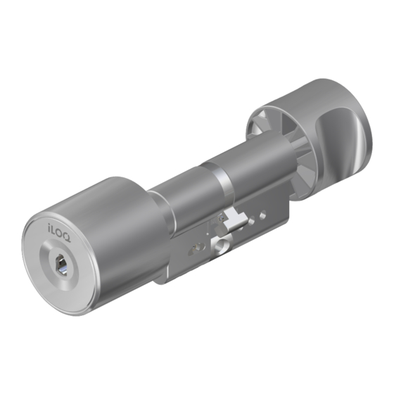
- Page 1 Page 1 of 16 D5S.XXX(A).SB D5S.XXX(L).SB EUROPROFILE LOCK CYLINDER MOUNTING AND CARE INSTRUCTIONS USER GUIDE...
-
Page 2: Table Of Contents
TABLE OF CONTENTS BEFORE INSTALLING ..............3 AFTER INSTALLATION ..............4 CARE ....................4 INSTALLATION OF ILOQ D5S.1XX SERIES ......... 4 INSTALLATION OF ILOQ D5S.2XX SERIES ......... 5 INSTALLATION OF ILOQ D5S.3XX SERIES ......... 8 INSTALLATION OF ILOQ D5S.4XX SERIES ......... 9 INSTALLATION OF ILOQ D5S.7XX SERIES ....... -
Page 3: Before Installing
2. iLOQ D5S cylinders must be installed and used carefully without excessive force. 3. The product should not be modified in any way except in accordance with the modifications described in these instructions. -
Page 4: After Installation
A. Ensure the cam is pointing downwards and slide lock cylinder through the lock case. B. Fix cylinder into lock case by iLOQ fixing screw (A10.64, part of the delivery), use tightening torque 0.9 ...1.1 Nm. If necessary, cut the screw to the correct length. -
Page 5: Installation Of Iloq D5S.2Xx Series
Page 5 of 16 5. INSTALLATION OF ILOQ D5S.2XX SERIES A. Remove knob from the other side of the cylinder as described in chapter 9. - Page 6 C. Ensure the cam is pointing downwards and slide lock cylinder through the lock case. D. Fix cylinder into lock case by iLOQ fixing screw (A10.64, part of the delivery), use tightening torque 0.9 … 1.1 Nm. If necessary, cut the screw to the correct length (calculation screw length: L = backset + 10 mm).
- Page 7 Page 7 of 16 knob F. Removing and installing the Outside G. Make sure the cylinder frame is a maximum of 1.0 mm from the door leaf or escutcheon...
-
Page 8: Installation Of Iloq D5S.3Xx Series
C. Make sure the cylinder frame is a maximum of 1.0 mm from the door leaf or escutcheon. D. Fix cylinder into lock case by iLOQ fixing screw (A10.64, part of the delivery), use tightening torque 0.9...1.1 Nm. If necessary, cut the screw to the correct length (calculation screw length: L = backset + 10 mm). -
Page 9: Installation Of Iloq D5S.4Xx Series
A. Ensure the cam is pointing downwards and slide lock cylinder through the lock case. B. Fix cylinder into lock case by iLOQ fixing screw (A10.64, part of the delivery), use tightening torque 0.9 ...1.1 Nm. If necessary, cut the screw to the correct length (calculation screw length: L = backset + 10 mm). -
Page 10: Installation Of Iloq D5S.7Xx Series
A. Ensure the cam is pointing downwards and slide lock cylinder through the lock case. B. Fix cylinder into lock case by iLOQ fixing screw (A10.64, part of the delivery), use tightening torque 0.9 ...1.1 Nm. If necessary, cut the screw to the correct length (calculation screw length: L = backset + 10 mm). -
Page 11: Removing And Installing The Outside Knob
Page 11 of 16 9. REMOVING AND INSTALLING THE OUTSIDE KNOB In some installation locations it is necessary to remove the outside knob from the lock cylinder. Follow these instructions to remove the knob. Re-installing with the same instructions in the opposite order. Be careful when inserting knob not to break the connections on the cylinder. - Page 12 Page 12 of 16 E. Remove the side screw and carefully detach the knob with the PCB. F. Remove the back-plate screw with a Torx 6 tool (not necessary to screw them completely out). G. Remove the backplate by rotating it counterclockwise.
-
Page 13: Cylinder Extensions
Page 13 of 16 10. CYLINDER EXTENSIONS 10.1 One side Cylinder length is easily adjustable in 5mm increments from 30 mm (basic length) to 100 mm by extension piece system. Extension piece can be added to both sides of the cam for the following cylinders: D5S.2xx ... - Page 14 Page 14 of 16 C. Insert the round extension piece inside the housing extension part opposite the side with the black sealing, so that the recess is placed next to the black O-ring. Please check if the O-ring is not damaged otherwise use a new one (spare part kit available “A5.005”). Insert the extension piece.
-
Page 15: Both Sides
Page 15 of 16 10.2 Both sides Same concept and doing than for the one-side extensions, please see chapter 10.1 One side. 10.3 Long neck In the case the outside housing of long-neck version will be extended instead three only two screws can be used to fix the backbone (see below). -
Page 16: General Notes
9. The key is to be kept securely so that only authorized person may have access. 10. In case of losing a key, blacklisting of the lost key shall be done with the iLOQ Manager software and affected locks shall be reprogrammed.
Need help?
Do you have a question about the D5S.(A).SB Series and is the answer not in the manual?
Questions and answers