Table of Contents
Advertisement
Quick Links
UM11457
88MW32X Reference Design User Guide
Rev. 1 — 4 August 2020
Document information
Information
Content
Keywords
Evaluation kit, reference design module, adapter board, Wi-Fi microcontroller,
power supply, antennas, GPIO, configuration pins
Abstract
User guide for 88MW320 and 88MW322 evaluation kits
User manual
Advertisement
Table of Contents

Subscribe to Our Youtube Channel
Related Manuals for NXP Semiconductors 88MW32 Series


Summary of Contents for NXP Semiconductors 88MW32 Series
- Page 1 UM11457 88MW32X Reference Design User Guide Rev. 1 — 4 August 2020 User manual Document information Information Content Keywords Evaluation kit, reference design module, adapter board, Wi-Fi microcontroller, power supply, antennas, GPIO, configuration pins Abstract User guide for 88MW320 and 88MW322 evaluation kits...
- Page 2 UM11457 NXP Semiconductors 88MW32X Reference Design User Guide Revision history Document revision history Revision Date Description Rev.1 4-Aug-2020 Initial release UM11457 All information provided in this document is subject to legal disclaimers. © NXP B.V. 2020. All rights reserved. User manual Rev.
-
Page 3: Introduction
UM11457 NXP Semiconductors 88MW32X Reference Design User Guide Introduction 1.1 Overview This document is a user guide for the RD-88MW322-QFN-1B-2A-v1.0 evaluation kit. This evaluation kit is based on the NXP 88MW322, an IEEE 802.11b/g/n Wi-Fi microcontroller. The RD-88MW320-QFN-1B-2A-v1.0 evaluation kit, which is based on the NXP 88MW320, is similar. -
Page 4: Evaluation Kit Overview
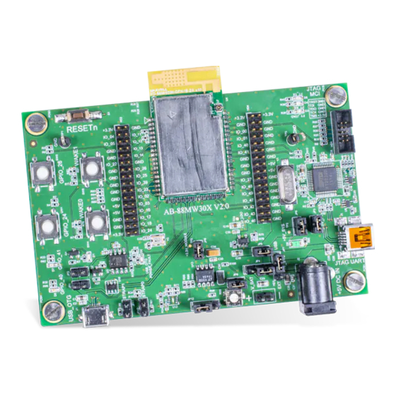
UM11457 NXP Semiconductors 88MW32X Reference Design User Guide Evaluation kit overview The evaluation kit includes a reference design module mounted on an adapter board. The reference design module is based on NXP 88MW322 wireless microcontroller. Figure 1 shows a picture of the evaluation kit. The reference design module is highlighted in yellow. -
Page 5: Reference Design Module Features
UM11457 NXP Semiconductors 88MW32X Reference Design User Guide 2.2 Reference design module features The reference design module is a stamp type module with the features shown in Table Table 2. Reference design key feature summary Parts Features Wireless SoC, U1 NXP 88MW322 IEEE 802.11b/g/n WLAN... -
Page 6: Adapter Board
UM11457 NXP Semiconductors 88MW32X Reference Design User Guide 2.3 Adapter board The adapter board is a 62 x 95 mm PCB with the key features shown in Table Table 3. Adapter board key feature summary Parts Features Power jack (5V ), J2 2 mm center-pin with 2.5 Amp rated DC jack... -
Page 7: Power Supply Options
UM11457 NXP Semiconductors 88MW32X Reference Design User Guide 2.4 Power supply options The reference design module can be powered by one of the three different sources through the adapter board. Table 4 shows how to select the power supply source by configuring the jumper on the adapter board. -
Page 8: Antennas
UM11457 NXP Semiconductors 88MW32X Reference Design User Guide Figure 5. Jumper and connector locations 2.5 Antennas The reference design module has an on-board PCB antenna and a W.FL RF connector(P/N IPEX 20369-001E) for external antenna. If both antennas are used, antenna diversity is supported. -
Page 9: Gpio Pins
UM11457 NXP Semiconductors 88MW32X Reference Design User Guide 2.6 GPIO pins Table 5 shows the available GPIO pins for both 88MW320 and 88MW322 reference design modules. Table 5. Available GPIO pins of the reference design modules 88MW320 88MW322 GPIO pin Up to 35 total... -
Page 10: Configuration Pins
UM11457 NXP Semiconductors 88MW32X Reference Design User Guide 2.7 Configuration pins By default the configuration pins Strap1 and Strap0 are disconnected, and the DUT is configured to boot from Flash. Configuration pins are muxed and used for the followings: • During boot-up, their states are read for the device operating mode •... -
Page 11: Getting Started
UM11457 NXP Semiconductors 88MW32X Reference Design User Guide Getting started This section describes the basic setup for the reference design module, and how to launch the Labtool for manufacturing (MFG) test. The test PC must be running on 64-bit Windows operating system. -
Page 12: Setup The Virtual Uart Interface
UM11457 NXP Semiconductors 88MW32X Reference Design User Guide 3.2 Setup the virtual UART interface The DUT can be accessed from the Test PC over the virtual UART interface. The Test PC is required to install a driver for its USB serial port. Follow the steps below: Step 1: Download the Zadig driver from https://zadig.akeo.ie/... -
Page 13: Test With Labtool
UM11457 NXP Semiconductors 88MW32X Reference Design User Guide 3.3 Test with Labtool For MFG test using Labtool, follow the steps below. Step 1: The evaluation kit needs to be configured to support MFG test mode. Read more in the section Wi-Fi MFG firmware and bridge Setup of 88MW32x Labtool User Guide. -
Page 14: Legal Information
NXP Semiconductors products in order to avoid a in modifications or additions. NXP Semiconductors does not give any... - Page 15 UM11457 NXP Semiconductors 88MW32X Reference Design User Guide Tables Tab. 1. 88MW320 and 88MW322 key differences ..3 Tab. 4. Power supply source selection Tab. 2. Reference design key feature summary ....5 configuration ............7 Tab. 3. Adapter board key feature summary ....6 Tab.
-
Page 16: Table Of Contents
UM11457 NXP Semiconductors 88MW32X Reference Design User Guide Contents Introduction ............3 Overview ............3 Related documents ..........3 Evaluation kit overview ........4 Kit package list ..........4 Reference design module features ....5 Adapter board ............6 Power supply options ........7 Antennas ............8...
Need help?
Do you have a question about the 88MW32 Series and is the answer not in the manual?
Questions and answers