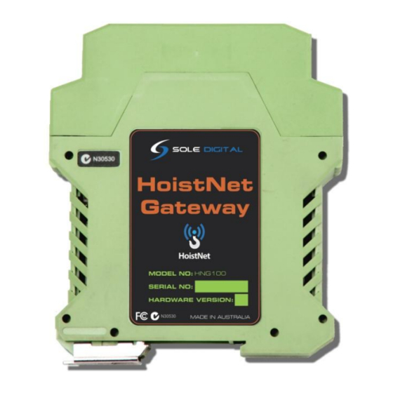
Summary of Contents for Sole Digital HNG100
- Page 1 HOISTNET GATEWAY Model HNG100, Version 1+ Installation and User Manual Revision 02 – December 2018 © CASWA Pty Ltd – 2014 1 | Page © CASWA Pty Ltd – 2014...
-
Page 2: Table Of Contents
CONTENTS OVERVIEW ..........................3 SPECIFICATIONS ........................3 2.1 Physical Specifications ......................3 2.2 Electrical Specifications ......................4 2.3 Communication Specifications ....................4 INSTALLATION DETAILS ......................5 3.1 Prior to Installation ......................... 5 3.2 Wiring Diagrams ........................6 3.2.1 Using Analog Outputs ....................6 3.2.2 Connecting RS485 Outputs .................. -
Page 3: Overview
1 OVERVIEW The HoistNet GateWay is a device for receiving up to two signals from other HoistNet devices and outputting the load via two fully isolated sinking or sourcing 4-20mA channels and/or a programmable RS485 serial interface. 2 SPECIFICATIONS 2.1 Physical Specifications Overall length (mm): Overall width (mm): Overall height (mm):... -
Page 4: Electrical Specifications
2.2 Electrical Specifications Parameter Description Units Supply voltage Supply current Analogue channel minimum output current imin Analogue channel maximum output current imax Isolation on analog and digital outputs 2000 isolate Voltage drop across analog output headroom Note1 Allowable operating temperature °C Note1: Extended operation at maximum temperature will reduce the life the device. -
Page 5: Installation Details
3 INSTALLATION DETAILS 3.1 Prior to Installation Before installing your HoistNet GateWay unit visually inspect the device and check that: (a) the type of input marked on the front of the device is appropriate for your application; (b) the case is not damaged and fits together securely; (c) terminals are secure;... -
Page 6: Wiring Diagrams
3.2 Wiring Diagrams 3.2.1 Using Analog Outputs The Analog Outputs are fully isolated and can be wired up as either sourcing (See Figure 3) or sinking outputs (See Figure 4). Figure 3: Connecting the Analog Outputs as Sourcing Outputs Figure 4: Connecting the Analog Outputs as Sinking Outputs 6 | Page ©... -
Page 7: Connecting Rs485 Outputs
3.2.2 Connecting RS485 Outputs Connect output RS485 terminals, marked Y and Z, on the HoistNet Gateway (terminals 16 and 15 respectively) to inputs A and B on the receiving device. Note: Terminals 13 and 14 marked as A and B on the HoistNet GateWay are RS485 inputs. Figure 5: Example of connecting the HoistNet GateWay to a RS485 receiver. -
Page 8: Installing The Fsu Application
4.2 Connecting to the Device The FSU will scan for Bluetooth enabled devices. This process takes approximately 10 seconds, when complete a list of all Sole Digital devices within range will be displayed. The HoistNet GateWay icon looks like this:... -
Page 9: Checking For Firmware
Double click the HoistNet GateWay you wish to configure to establish a connection. 4.3 Checking for Firmware To check the current firmware of the Hoistnet Gateway, right click on the Hoistnet Gateway Icon within the FSU discovery screen and choose <manage firmware>. A new window will open. - Page 10 When you pick the firmware you want to update the Hoistnet GateWay the <Apply Firmware> button becomes visible. Click the <Apply Firmware> button to begin the firmware update. A progress bar will begin showing how far along the firmware update is. When its complete it will show a pop up message.
-
Page 11: Hoistnet Gateway Configuration Screen
4.4 HoistNet GateWay Configuration Screen Once you are up to date with the latest firmware version you can double click the Hoistnet GateWay you want to configure and the following screen will appear. This screen shows the: ID (see section 4.4.1 for configuring this); ... - Page 12 A box will appear asking you which HoistNet enabled device you want to connect to: Select the device that has the load signal to be used and press <OK>. If you select a LiftlogXL, another window will popup asking you which hook to connect to (Main, Aux or Combined Load).
-
Page 13: Configuring Analog Outputs
4.5 Configuring Analog Outputs A HoistNet GateWay can convert the HoistNet inputs into analog 4-20mA outputs. The behaviour of each output needs to be configured using the 'Analog 1' and 'Analog 2' tabs for the first and second input respectively. To configure the 4-20mA output signal, two parameters are required: (a) The expected mA output value corresponding to a 0kg load;... -
Page 14: Routine Maintenance
This screen contains the two configurable RS485 fields and also shows the resulting string being sent via the RS485 interface. Define the required RS485 serial format in the 'Format' field incorporating the required loads using the following codes: %o = first load in tonnes %O = first load in kilograms %t = second load in tonnes %T = second load in tonnes %r = carriage return... -
Page 15: Appendix A: Fsu System Requirements
Analog Output current Insufficient excitation Ensure at least 8V Headroom for Gateway in current “Maxing out” voltage. loop No current in analog Reverse polarity Check the wiring to the Gateway output loop APPENDIX A: FSU SYSTEM REQUIREMENTS The minimum requirements for operating CASWA’s Field Service Utility (FSU) and Link-2 Bluetooth modem are: ...


Need help?
Do you have a question about the HNG100 and is the answer not in the manual?
Questions and answers