
Related Manuals for weintek iR-ETN


Summary of Contents for weintek iR-ETN
- Page 1 User Manual iR-ETN User Manual This guide walks through important information about iR-ETN UM018002E_20200518...
-
Page 2: Table Of Contents
Table of Contents Product Overview ....................1 Specifications ......................2 LED Indicators ......................3 L.V LED ......................3 IO RUN/ERR LED ..................... 3 ENET RUN/ERR ....................3 RJ45 ........................ 3 RJ45 Interface ......................4 Reset Button ......................4 IP Address Setup ..................... 4 Reset Button .................... - Page 3 12. Ethernet Cascading ....................21 13. EasyRemoteIO ....................... 22 14. Connecting with CODESYS ..................24 15. Connecting CODESYS with EasyBuilder Pro ............28 15.1 Creating .xml File ..................29 16. Importing CODESYS Modbus TCP using EasyRemote I/O for iR-ETN ....32...
-
Page 4: Product Overview
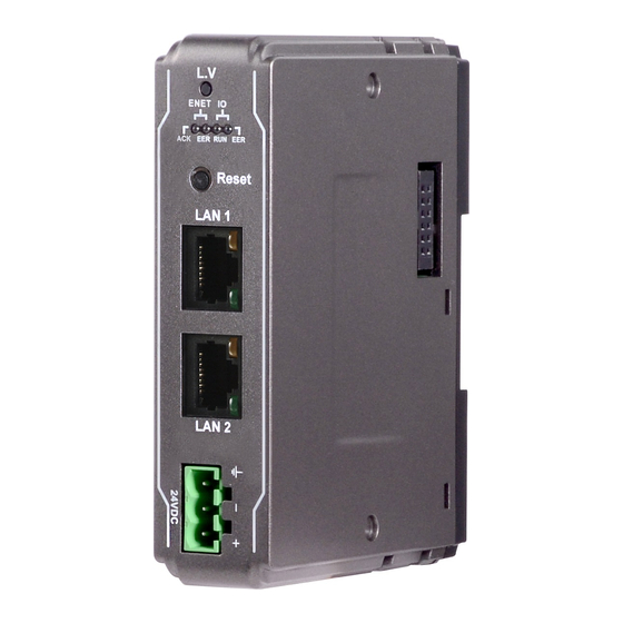
User Manual Top View Top View 1. Product Overview 27mm [1.06"] 81mm [3.19"] 27mm [1.06"] 81mm [3.19"] Side View Side View Front View Side View Front View Reset Button Expansion Connector Ethernet Port LAN 1 Ethernet Port LAN 2... -
Page 5: Specifications
User Manual 2. Specifications Communication Interface Specifications Model iR-ETN Number of Bus Terminals Depends on Power Consumption Digital Input Point Max. 512 Expansion I/O Module Digital Output Point Max. 256 Analog Input Channel Max. 64 Analog Output Channel Max. 64... -
Page 6: Led Indicators
User Manual 3. LED Indicators L.V LED L.V LED state Description 24V power normal Blinking Detect 24V power 24V power error IO RUN/ERR LED RUN LED ERR LED Description Power off or no power Blinking IO initiating Blinking IO initiation error... -
Page 7: Rj45 Interface
User Manual LINK /ACT LED No communication. Blinking There is activity on this port. 4. RJ45 Interface RJ-45 Signal Name Descriptions Transmit + Transmit + Receive + **** **** Receive - **** **** Case Shield 5. Reset Button Press and hold the reset button for more than 2 seconds after the unit starts running properly, and wait until ENET ERR LED blinks. -
Page 8: Register Mapping
*TCP/IP Register Settings will take effect after cold reset or after giving Device Reset Warm command. Device Information Register Address Read/Write Data size Description 4word 3000 0BB8 Read Vendor name string 8 char: “weintek” (ASCII) 1word 3004 0BBC Read Product Code of iR-ETN is 0x0702 Read 1word 3005 0BBD Firmware revision V1.23.4, 0x1234... -
Page 9: Module Information Register
User Manual 10033 2731 Read 1word Number of modules Read 1word 10035 2733 Number of points of Digital Input 10036 2734 Read 1word Number of points Digital Output 10037 2735 Read 1word Number of Analog channels of Input register... -
Page 10: Product Code List
User Manual Product Code List Item Product Code iR-DI16-K 0154h iR-DM16-P 0351h iR-DQ16-P 0251h iR-DM16-N 0352h iR-DQ16-N 0252h iR-DQ08-R 0243h iR-AQ04-VI 0525h iR-AI04-VI 0425h iR-AM06-VI 0635h iR-AI04-TR 0426h iR-COP 0701h iR-ETN 0702h iR-PU01-P 0819h Special Register Address Read/Write Data size... -
Page 11: The Default Value
User Manual ….. ….. ….. ….. ….. 6164 1814 Read/Write 1word Digital Output Error Value (bit511-495) Analog Output Error Mode 6165 1815 Read/Write 1word (channel 15-0) Analog Output Error Mode 6166 1816 Read/Write 1word (channel 31-16) 0:Keep last value... -
Page 12: Reading And Writing Ir-Pu01-P Objects
Stop 0x0001 Operation 0x0002 Pre-operational 0x0080 Reset application 0x0081 Reset communication 0x0082 8. Modbus Mapping The following is an example showing that when iR-ETN is connected with multiple modules, the address mapping and input/output bit mapping can be as follows:... -
Page 13: Ibus Information Register
Slot#9 iR-PU01-P Slot#10 iR-PU01-P iBus Information Register Address Description Value 10000 2710 Slot 0 Product code (iR-ETN Device) 0x0702 (iR-ETN) 10001 2711 Slot 1 Product code (Module) 0x0154 (iR-DI16-K) 10002 2712 Slot 2 Product code (Module) 0x0251 (iR-DQ16-P) 10003... -
Page 14: Digital Output Bit Mapping To Modbus
User Manual Digital Output Bit Mapping to Modbus Slot Module Bit offset (0x0000~0x0027) Function Code Slot#1 iR-DI16-K Slot#2 iR-DQ16-P 0x0000~0x000F (Digital Output 0~15) 5, 15 Slot#3 iR-DM16-P 0x0010~0x0017 (Digital Output 0~7) 5, 15 Slot#4 iR-DQ08-R 0x0018~0x001F (Digital Output 0~7) - Page 15 User Manual (Axis 1) Axis 1 variable instance output 40516~40531 Slot#9 Axis 2 variable instance input 40032~40047 iR-PU01-P (Axis 2) Axis 2 variable instance output 40532~40547 Slot#10 Axis 3 variable instance input 40048~40063 iR-PU01-P (Axis 3) Axis 3 variable instance output 40548~40563 The following are examples explaining variable instance mapping.
- Page 16 User Manual 40506 Axis 0 Target velocity (Lo word) DINT Signed 32 40507 Axis 0 Target velocity (Hi word) 40508 Axis 0 Profile acceleration (Lo word) DINT Signed 32 40509 Axis 0 Profile acceleration (Hi word) 40510 Axis 0 Profile deceleration(Lo word)
-
Page 17: Ethernet/Ip
User Manual 9. EtherNet/IP Object List Name Object Type Object Code (Hex) Identity Standard Object Message Router Standard Object Assembly Standard Object Connection Manager Standard Object TCP/IP Interface Standard Object Ethernet Link Standard Object Module Register Manufacturer Defined Object... -
Page 18: Class Attributes & Instance Attributes
User Manual 9.3.1 Class Attributes & Instance Attributes None Connection Manager Object Class Code: 06 9.4.1 Class Attributes & Instance Attributes None Ethernet Link Object Class Code: F6 9.5.1 Services Service Code Class Instance Name 0x01 ● Get Attribute All 0x0E ●... -
Page 19: Service
User Manual 9.6.1 Service Service Code Class Instance Name 0x0E ● ● Get Attribute Single 0x01 ● Set Attribute Single 9.6.2 Class Attributes Instance ID Attribute ID Read/Write Name Data Type Value Read Revision UINT Read Max Instance UINT 9.6.3 Instance Attributes... -
Page 20: Configuration Control Attribute
Data Type Value Slot# Module Read/Write Module Register# Register# The following is an example showing the mapping of Instance ID and Attribute ID when iR-ETN is connected to the following modules. Slot Module Name Slot#1 iR-AI04-VI Slot#2 iR-DQ16-P Slot#3 iR-DM16-P... -
Page 21: Ibus Object
User Manual Channel 1 Output Mode Channel 2 Output Mode Channel 3 Output Mode ……… ……… ……… 16# Error Code For more information on registers, please see the user manual for each module. iBus Object Class Code: 71 9.8.1 Services... -
Page 22: Axis Register Object
Axis3 87hex Axis4 10. iBus Error Handling When communication with the module is lost, iR-ETN can report an error and stop module communication. The following actions can be taken: Set Special Register #10045 (273Dh) to 1 to ignore this error. - Page 23 User Manual Set Special Register #10045 (273Dh) to 0 to report this error. Send Device Command Special Register #6000 (1770h) to reboot iBus. iBus Error Flowchart:...
-
Page 24: Power Consumption
User Manual 11. Power Consumption Type Device Consumption(5V) Power Supply(5V) iR-ETN 220mA/1.1w 2A/10w Coupler iR-COP 170mA/0.85w 2A/10w iR-DM16-P 130mA/0.65w iR-DM16-N 130mA/0.65w iR-DQ08-R 220mA/1.1w Digital I/O iR-DQ16-N 205mA/1.02w iR-DQ16-P 196mA/0.984w iR-DI16-K 83mA/0.418w iR-AQ04-VI 65mA/0.325w iR-AI04-VI 70mA/0.35W Analogl I/O iR-AM06-VI 70mA/0.35W iR-AI04-TR 65mA/0.325w... -
Page 25: Easyremoteio
User Manual 13. EasyRemoteIO EasyRemoteIO is an easy-to-use tool for configuring the parameters of iR-ETN. This tool can be found in the installation file of the latest version of EasyBuilder Pro. For more information on EasyRemoteIO, please see EasyRemoteIO User Manual. - Page 26 Select [Online] » [Change IP] to set the iR-ETN’s IP address. 4. Check Parameter with Monitor: Select [Online] » [Start Monitoring] or press Shift + M on the keyboard to activate the connection with iR-ETN. The device status and module status can be viewed via EasyRemoteIO.
-
Page 27: Connecting With Codesys
User Manual 5. Export EtherNet/IP EDS file. 14. Connecting with CODESYS For more information on cMT+CODESYS and iR Remote I/O, please see: UM018003E_cMT_Codesys_Install_UserManual_eng.pdf 1. Preparation: Please add Weintek Built-in CODESYS device following the instructions in this document. - Page 28 Double click [Device] and select [Scan network] to find the cMT device you want to connect. 3. Creating Ethernet Device: Under Ethernet (Ethernet) create a Modbus_TCP_Master device which represents CODESYS Ethernet Port of the cMT device, and create a Modbus_TCP_Slave device which represents iR-ETN’s Ethernet Port.
- Page 29 User Manual 4. Parameter setting Ethernet: Double click [Ethernet] and select [Interface] to find the cMT device connected just now. Modbus_TCP Master: Select auto-reconnect. Modbus_TCP Slave:...
- Page 30 User Manual Set the iR-ETN IP and set Unit-ID to 1. 5. Modbus Slave Channel: Add Remote I/O module channels here. Use Read Discrete Inputs (Function Code 2) for input and use Write Multiple Coils (Function Code 15) for output. Please set correct offset and length for each channel, or see an example shown in Chapter 8 in this manual.
-
Page 31: Connecting Codesys With Easybuilder Pro
User Manual 8. Download Program and Run: Follow the steps: [Build] » [Login] » [Run]. Devices successfully connected will have a green circle mark. 15. Connecting CODESYS with EasyBuilder Pro 1. Symbol Configuration: Create a [Symbol configuration] object under Application. -
Page 32: Creating .Xml File
User Manual 15.1 Creating .xml File 1. “Build” Command for Selecting Variables. 2. Select PLC_PRG Variables. 3. Create .xml File: Click [Build] » [Generation code] and find the .xml file in program saving location. - Page 33 User Manual 4. Importing .xml File in EasyBuilder Pro. 5. Adding a Device: Add Weintek Built-in CODESYS driver into the device list. 6. Importing Tags: Use Tag Manager to import .xml file.
- Page 34 User Manual 7. Select Tag in Object Settings Dialog.
-
Page 35: Importing Codesys Modbus Tcp Using Easyremote I/O For Ir-Etn
User Manual 16. Importing CODESYS Modbus TCP using EasyRemote I/O for iR-ETN 1. Search for iR-ETN on the network. 2. Export PLCopenXML file. 3. Launch CODESYS and add Modbus_TCP_Master. 4. Import PLCopenXML file. Click Modbus_TCP_Master and select [Project] »... - Page 36 User Manual 5. Import is completed. 6. Read/Write channels and initial parameters are built.
- Page 37 CODESYS® is a trademark of 3S-Smart Software Solutions GmbH. Other company names, product names, or trademarks in this document are the trademarks or registered trademarks of their respective companies. This document is subject to change without prior notice. Copyright© 2020 Weintek Lab., Inc. All rights reserved.
Need help?
Do you have a question about the iR-ETN and is the answer not in the manual?
Questions and answers