
Related Manuals for VIPA CP 1413plus

Summary of Contents for VIPA CP 1413plus
- Page 1 Manual CP 1413plus Order No.: VIPA SSN HB83E Rev. 00/07 Subject to change to cater for technical progress...
- Page 2 jkjlj...
- Page 3 CP1413plus manual The information contained in this manual is subject to change without notice. VIPA GmbH does not accept any liabilities, express or implied, with this document. Any hardware and software described in this manual is supplied on the basis of a general licence. Software usage and disclosure to third parties is only permitted where this is subject to the contractual conditions.
- Page 4 ISA- and PCI-bus interfaces and for the required software. Chapter 4: Programming This chapter contains a complete reference for the VIPA H1 interfacing software. This includes specifications of the H1 layer 4 and the PLC layer 7 programming interface.
-
Page 5: Table Of Contents
2.4.2 Thin/thick ethernet cable combination network-layout........2-15 2.5 Twisted Pair ......................2-16 2.5.1 Twisted pair-cable network-layout ..............2-16 2.6 Planning a network-layout..................2-18 2.7 Standards and specifications ................2-19 3 VIPA CP1413PLUS NETWORK ADAPTER ..............3-1 3.1 Z'nyx PCI-bus adapter...................3-2 3.1.1 Properties ......................3-2 3.1.2 Shipment ......................3-2 3.1.3 Hardware installation ..................3-4 3.1.4 Software installation ..................3-7... - Page 6 7.1 General ........................7-1 7.2 Uninstalling older Windows NT drivers.............. 7-1 7.3 Installation of the VIPA CP1413plus network adapter........7-1 7.4 Installation of the H1 driver V3.xx for Windows NT 3.51........7-2 7.4.1 Installation of SSN-BG88 (Z'nyx adapter) for PCI bus ........7-2 7.4.2 Installation of SSN-BG85C (3COM adapter) for ISA-Bus ........
- Page 7 CP1413plus manual Contents 7.6 Programming......................7-7 7.6.1 General notes on programming................7-7 7.6.2 H1 Layer 4 programming interface ..............7-21 7.6.3 PLC Layer 7 software interface ..............7-55 7.6.4 PLC Net file functions..................7-85 7.6.5 Files, constants and structures...............7-97 Appendix ....................A-1 A Technical data ......................A-1 B Abbreviations ......................
- Page 8 Contents CP1413plus manual Rev. 00/07...
-
Page 9: Introduction
1 Introduction 1.1 Safety and handling precautions for the user 1.1.1 Handling electrostatically sensitive modules 1.1.2 Shipping electrostatically sensitive modules 1.1.3 Tests and modifications to electrostatically sensitive modules 1.2 General 1.3 Operation 1.4 Construction 1.5 Communication functions 1.6 Access functions 1.7 Special features... - Page 11 1.1 Safety and handling precautions for the user 1.1.1 Handling electrostatically sensitive modules VIPA-modules contain MOS LSI components. These components are highly susceptible to voltage transients which may occur when an electrostatic discharge takes place. The following sign is affixed to these modules: This symbol is attached to the module, the frame or the packing box and it indicates the sensitive nature of the module.
- Page 12 Safety and handling precautions for the user CP1413plus manual 1.1.2 Shipping electrostatically sensitive modules You should always use the original packing when a module must be shipped. In addition you may also pack the module in a conductive enclosure. Conductive enclosures consist of antistatic foils or boxes made of metallized plastic.
-
Page 13: General
, WINDOWS 3.11, WINDOWS 95, WINDOWS NT and OS/2 Depending on the type of PC bus you may choose between two types of VIPA network modules: PCI-Bus board Z'nyx -board:(Order No.:VIPA SSN-BG88) Locator Board description: chapter 3.1 Hardware installation: chapter 3.1.3 Software installation: chapter 3.1.4... -
Page 14: Operation
Operation CP1413plus manual 1.3 Operation You must install the CP1413plus board directly into your PC. The board has 3 interfaces: 1. An interface for the Industrial Ethernet (H1) LAN cable via a transceiver 2. An interface for Industrial Ethernet (H1) using thin-ethernet cable 3. -
Page 15: Communication Functions
CP1413plus manual Introduction 1.5 Communication functions In addition to the general test applications which are intended for common functional tests the module is also provided with a programming interface which is independent of the operating system: • MS-DOS: C-interface as a library (C-source code) •... - Page 16 Special features CP1413plus manual Rev. 00/07...
-
Page 17: Network Planning
2 Network planning 2.1 Ethernet network-terminology 2.2 Thin-ethernet-cable networks 2.2.1 Thin-ethernet-cable network-layout 2.2.2 Regulations and specifications 2.2.3 Technical data thin-ethernet 2.3 Thick-ethernet-cable networks 2.3.1 Thick-ethernet-cable network-layout 2-10 2.3.2 Regulations and specifications 2-11 2.3.3 Technical data thick-ethernet 2-13 2.4 Combining thin/thick ethernet cable in networks 2-14 2.4.1 Combination of thin/thick ethernet cable hardware 2-14... -
Page 19: Fig. 2-1: Parts Of An Ethernet Network
CP1413plus manual Network planning 2 Network planning 2.1 Ethernet network-terminology An ethernet network provides a communication link between different stations on the network. The stations on the network may consist of personal computers, industrial computers, automation equipment etc. Stations are connected to the network and located a certain minimum distance from each other. - Page 20 Ethernet network-terminology CP1413plus manual Three types of ethernet cable exist: • Thin-ethernet-cable (also called thin ethernet cable or Cheapernet-cable). • Thick-ethernet-cable (also called thick ethernet cable or standard ethernet-cable or yellow-cable). • Twisted pair-cable (telephone cable) Thin ethernet-cable is far more economical than thick ethernet-cable. This applies to the cost of the cable, the cost of installation and any additional hardware.
-
Page 21: Thin-Ethernet-Cable Networks
BNC-connectors are used to interconnect two thin-ethernet network cables. Where two portions of a thin-ethernet network must be linked these connectors have a distinct advantage over T-pieces. You may obtain these BNC-connectors from VIPA GmbH. BNC-T-pieces The two sockets located at opposite ends of the T-piece provide the connection to the BNC-connectors on the thin-ethernet cable. -
Page 22: Fig. 2-2: Thin Ethernet Network Hardware
Thin-ethernet-cable networks CP1413plus manual PCI-adapter ISA-adapter Fig. 2-2: Thin ethernet network hardware Rev. 00/07... -
Page 23: Thin-Ethernet-Cable Network-Layout
CP1413plus manual Network planning 2.2.1 Thin-ethernet-cable network-layout Here follows a summary of the restrictions and the rules that apply to a thin-ethernet-cable network. Fig. 2-3 is an illustration of this summary. Restrictions • Maximum number of network segments: (3 coaxial segments with network stations and 2 interconnecting segments without network stations) •... -
Page 24: Regulations And Specifications
Thin-ethernet-cable networks CP1413plus manual 2.2.2 Regulations and specifications Certain basic regulations must be observed when planning or installing a thin ethernet network: • The cabling of a network consists of a number of segments. Each segment must be terminated with its characteristic impedance (terminator) of 50 Ω. •... - Page 25 CP1413plus manual Network planning Guidelines for the routing and installation of network components • As a rule, a minimum distance of 1m is prescribed with respect to electrical equipment, cabling and other components that could produce electromagnetic and electrostatic fields. This includes parallel runs of power or high-tension cables, circuit breakers etc.
-
Page 26: Thick-Ethernet-Cable Networks
Thick-ethernet-cable networks CP1413plus manual 2.3 Thick-ethernet-cable networks Thick-ethernet-cable network hardware This chapter contains a description and an illustration (Fig. 2-4) of the hardware required for a thick-ethernet-network. Network adapter Network adapters are installed in every station on the network and linked by means of a network cable to provide the communication medium between these stations. -
Page 27: Fig. 2-4: Thick-Ethernet Network Hardware
CP1413plus manual Network planning PCI-adapter ISA-adapter Fig. 2-4: thick-ethernet network hardware Rev. 00/07... -
Page 28: Thick-Ethernet-Cable Network-Layout
Thick-ethernet-cable networks CP1413plus manual 2.3.1 Thick-ethernet-cable network-layout Here follows a summary of the restrictions and the rules that apply to a thick-ethernet-cable network. Fig. 2-5 is an illustration of this summary. Restrictions • Maximum number of network segments: (3 coaxial segments with network stations and 2 interconnecting segments without network stations) •... -
Page 29: Regulations And Specifications
CP1413plus manual Network planning 2.3.2 Regulations and specifications Certain basic regulations must be observed when planning or installing a thick ethernet network: • The cabling of a network consists of a number of segments. Both ends of each segment must be terminated with its characteristic impedance (terminator) of 50 Ω. - Page 30 Thick-ethernet-cable networks CP1413plus manual Guidelines for the routing and installation of network components: • As a rule, a minimum distance of 1m is prescribed with respect to electrical equipment, cabling and other components that could produce electromagnetic and electrostatic fields. This includes parallel runs of power or high-tension cables, circuit breakers etc.
-
Page 31: Technical Data Thick-Ethernet
CP1413plus manual Network planning 2.3.3 Technical data thick-ethernet Coaxial cable 50 Ω ± 2 Ω Impedance ± 3 Ω with a period > 2 m Impedance linearity Inductivity 0,21 µH/km 85 pF ± 5 pF Capacity ≤ 18 dB/km for a 10 MHz sine wave Attenuation ≤... -
Page 32: Combining Thin/Thick Ethernet Cable In Networks
Combining thin/thick ethernet cable in networks CP1413plus manual 2.4 Combining thin/thick ethernet cable in networks It is possible to combine thin-ethernet and thick-ethernet cabling in a single network.. The lower price of the thin-ethernet cable may provide a more cost-effective solution than a system that is purely based on thick-ethernet cable. -
Page 33: Thin/Thick Ethernet Cable Combination Network-Layout
CP1413plus manual Network planning 2.4.2 Thin/thick ethernet cable combination network-layout This chapter describes a method of combining thin ethernet cable and thick ethernet cable in a single network segment. This method employs as much thin ethernet cable as possible. Fig 2-7 illustrates this technique of combining thin and thick ethernet cable. -
Page 34: Twisted Pair
Twisted Pair CP1413plus manual 2.5 Twisted Pair Twisted Pair network hardware A twisted pair-network can only have a star-type configuration. This topology requires a hub that supports the star-type configuration. The following paragraphs contain a description of the hardware required for implementing a twisted pair network. -
Page 35: Fig. 2-9: Twisted Pair Network Hardware
CP1413plus manual Network planning PCI-adapter ISA-adapter Twisted Pair plug Twisted Pair cable Star coupler (Hub) Power supply Tx Rx Tx Rx Tx Rx Tx Rx Tx Rx Tx Rx Fig. 2-9: Twisted pair network hardware Rev. 00/07 2-17... -
Page 36: Planning A Network-Layout
Planning a network-layout CP1413plus manual 2.6 Planning a network-layout At this point you are aware of the limitations of the different cabling systems, and you can provide answers to the following questions with respect to the network that you have to implement: Determination of network requirements •... -
Page 37: Standards And Specifications
LAN and other basic principles that are important for communicating on the network. The VIPA H1-network was developed to satisfy the ISO standards and specifications. The standards and specifications for networking systems were determined by international and national committees. - Page 38 Standards and specifications CP1413plus manual 2-20 Rev. 00/07...
-
Page 39: Vipa Cp1413Plus Network Adapter
3 VIPA CP1413plus network adapter 3.1 Z'nyx PCI-bus adapter 3.1.1 Properties 3.1.2 Shipment 3.1.3 Hardware installation 3.1.4 Software installation 3.2 3COM ISA-bus adapter 3-30 3.2.1 Properties 3-30 3.2.2 Shipment 3-30 3.2.3 Hardware installation 3-32 3.2.4 Software installation 3-39 3.3 Entry into protocol file [H1PROT_NIF]... -
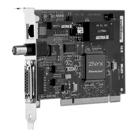
Page 41: Fig. 3-1: Cp1413Plus For Pci-Bus
VIPA CP1413plus network adapter 3 VIPA CP1413plus network adapter Note Depending on the type of bus in your PC, VIPA can supply two different network adapters: • for PCI-bus: Z'nyx-adapter (Order-No.: VIPA SSN-BG88) • for ISA-bus: 3Com-adapter (Order.-No.: VIPA SSN-BG85C) PCI-bus adapter Z'nyx : (Best.-Nr.:VIPA SSN-BG88) -
Page 42: Properties
Z'nyx PCI-bus adapter CP1413plus manual 3.1 Z'nyx PCI-bus adapter 3.1.1 Properties • Two LED’s display adapter and network activity • Support for plug- and play technology, i.e. fully automatic recognition of the adapter, no user intervention required. • Auto Select Media Type (automatic recognition of the connector that is connected to the network). - Page 43 CP1413plus manual VIPA CP1413plus network adapter Disk 2: SW83Z disk 1/2, adapter 1413plus H1-bus - Driver software H1 for the operating systems : • MS-DOS ® 5.0 and 6.22 • Windows ® ® 3.1 and WfW 3.11 • Windows ®...
-
Page 44: Hardware Installation
Z'nyx PCI-bus adapter CP1413plus manual 3.1.3 Hardware installation 3.1.3.1 Installing the adapter The adapter must be installed in the PC before it is configured. Please note the following: 1. Switch your computer off. Remove the power cable. 2. Remove the covers from your computer according to the manufacturers instructions. 3. -
Page 45: Fig. 3-2: Pci Adapter Connection To A Thin-Ethernet-Network
CP1413plus manual VIPA CP1413plus network adapter 3.1.3.2 Network cabling 3.1.3.2.1 Thin-ethernet network Fig. 3-2: PCI adapter connection to a thin-ethernet-network 3.1.3.2.2 Thick-ethernet network Fig. 3-3: PCI adapter connection to a thick ethernet-network Rev. 00/07... -
Page 46: Fig. 3-4: Pci Adapter Connection To A Twisted Pair-Network
Z'nyx PCI-bus adapter CP1413plus manual 3.1.3.2.3 UTP-network Fig. 3-4: PCI adapter connection to a twisted pair-network Rev. 00/07... -
Page 47: Software Installation
CP1413plus manual VIPA CP1413plus network adapter 3.1.4 Software installation The software installation depends on the configuration and on the operating system. The selected combination depends on the operating system and other required protocols. Below follow a number of sample installations for certain protocols and operating systems. Other protocols may be installed in a similar manner. - Page 48 Z'nyx PCI-bus adapter CP1413plus manual 3.1.4.1 MS-DOS installation 3.1.4.1.1 MS-DOS Version A without additional protocols Installation with the following components: - H1 under MS-DOS without additional protocols Step 1 Install the network adapter into your PC (see chapter 3.1.3) Step 2 Set the required parameters, if necessary.
- Page 49 CP1413plus manual VIPA CP1413plus network adapter Extract from the file C:\H1_DOS\PROTOCOL.INI [PROT_MAN] DRIVERNAME = PROTMAN$ [IBMLXCFG] ZX312_NIF = ZX312.NIF H1PROT_NIF = H1PROT.NIF [H1PROT_NIF] DRIVERNAME = H1PROT$ BINDINGS = ZX312_NIF ;example for a station address (own station address) NETADDRESS = I0020D582FFFF MAXVERBINDUNGEN = 10 The leading "I"...
- Page 50 3.1.4.1.2 MS-DOS Version B with Windows for Workgroups Installation including the following components: - H1 with Windows for Workgroups (WfW) components Step 1 Install the VIPA CP1413plus H1 network adapter as described in chapter 3.1.3. Step 2 Set the required parameters, if necessary. Step 3 When Windows for Workgroups (WfW) is initialized the network configuration is requested automatically.
- Page 51 CP1413plus manual VIPA CP1413plus network adapter Step 4 restart your PC. WfW should start and run correctly. Once WfW has started the network services are available. You can verify this by means of the file manager. Step 5 Please copy the H1 directory for Windows multi-protocol onto your hard disk.
- Page 52 Z'nyx PCI-bus adapter CP1413plus manual Subsequently you must please change the parameter NETADDRESS in the section H1PROT_NIF] of the file C:\WINDOWS\PROTOCOL.INI Please ensure that the network address is unique! Step 9 Restart the PC and make sure that all programs are loaded without error messages. Make sure that Windows for Workgroups also starts without error messages.
- Page 53 The installation includes the following components: - H1 with Windows for Workgroups (WfW) components - Novell IPX Step 1 Install the VIPA CP1413plus H1 network adapter as described in chapter 3.1.3. Step 2 Set the required parameters, if necessary. Step 3 When Windows for Workgroups (WfW) is initialized the network configuration is requested automatically.
- Page 54 Z'nyx PCI-bus adapter CP1413plus manual Step 4 restart your PC. WfW should start and run correctly. Once WfW has started the network services are available. You can verify this by means of the file manager. Step 5 Please copy the H1 directory for Windows multi-protocol onto your hard disk. xcopy A:\H1_DOS\VAR_C\*.* C:\H1_DOS\ Step 6 Add the lines from the file C:\H1_DOS\CONFIG.SYS to your C:\CONFIG.SYS file:...
- Page 55 CP1413plus manual VIPA CP1413plus network adapter The file C:\H1_DOS\PROTOCOL.WIN is an example of a valid installation and may be used as is. copy c:\h1_dos\protocol.win c:\windows\protocol.ini Subsequently you must please change the NETADDRESS parameter in the section [H1PROT_NIF] of the file C:\WINDOWS\PROTOCOL.INI.
- Page 56 This installation includes the following components: - H1 under MS-DOS - IBM LAN Requester 4.0 Step 1 Install the VIPA CP1413plus H1 network adapter as described in chapter 3.1.3. Step 2 Set the required parameters, if necessary. Step 3 Install the IBM LAN Requester according to the instructions supplied by IBM. Next you must please install the "ZNYX ZX312/V PCI Ethernet Driver"-adapter.
- Page 57 CP1413plus manual VIPA CP1413plus network adapter Step 7 Check that the following line exists in your C:\AUTOEXEC.BAT file: C:\net\net start If this line does not exist, please add it to the beginning of the file. Step 8 Append the contents of the file C:\H1_DOS\PROTOCOL.INI to the end of the file C:\NET\PROTOCOL.INI.
- Page 58 Z'nyx PCI-bus adapter CP1413plus manual 3.1.4.1.5 MS-DOS Version E with IBM LAN Requester 4.0 and Novell IPX This installation includes the following components: - H1 under MS-DOS - IBM LAN Requester 4.0 - Novell IPX Install the IBM LAN Requester and Novell NetWare according to the instructions provided by the respective manufacturer.
- Page 59 CP1413plus manual VIPA CP1413plus network adapter 3.1.4.1.6 MS-DOS Version F with 2 network adapters, no additional protocols This installation includes the following components: - H1 with 2 network adapters under MS-DOS, without any additional protocols. Step 1 Install the network adapter in your PC (see chapter 3.1.3) Step 2 Set the required parameters, if necessary.
- Page 60 Z'nyx PCI-bus adapter CP1413plus manual Step 6 Now you must please modify the file C:\H1_DOS\PROTOCOL.INI as follows: 1.)the entries in the section [ZX312_NIF] and [ZX3122_NIF] Use the parameters supplied by the program diag312.exe for the Device specification. 2.)the NETADDRESS parameter in section [H1PROT_NIF] Please ensure that the network address is unique! Extract from C:\H1_DOS\PROTOCOL.INI [PROT_MAN]...
- Page 61 CP1413plus manual VIPA CP1413plus network adapter 3.1.4.2 OS/2 installation 3.1.4.2.1 OS/2 Version A without additional protocols This installation includes the following components: - H1 under OS/2 without additional protocols Step 1 Install the network adapter into your PC (see chapter 3.1.3)
- Page 62 Z'nyx PCI-bus adapter CP1413plus manual Extract from the file PROTOCOL.INI [PROT_MAN] DRIVERNAME = PROTMAN$ [IBMLXCFG] ZX312_NIF = ZX312.NIF H1PROT_NIF = H1PROT.NIF [H1PROT_NIF] DRIVERNAME = H1PROT$ BINDINGS = ZX312_NIF ;Example for a station address (own station address) NETADDRESS = I00001C011010 MAXVERBINDUNGEN = 32 MAXSENDEBUFFER = 32 MAXACKBUFFER = 64 The leading "I"...
- Page 63 Note you must have the IBM LAN Requester! Step 1 Install the VIPA CP1413plus H1 network adapter as described in chapter 3.1.3. Step 2 Boot into DOS and set any required parameters Boot OS/2 because the following steps are applicable only to OS/2.
- Page 64 - Novell IPX Note you must have the IBM LAN Requester and the Novell NetWare drivers for OS/2! Step 1 Install the VIPA CP1413plus H1 network adapter as described in chapter 3.1.3. Step 2 Boot into DOS and set any required parameters Boot OS/2 because the following steps are applicable only to OS/2.
- Page 65 H1-Protokoll". Please select this protocol. Step 4 If you have installed a number of network adapters and some of these are not VIPA CP1413plus adapters, you must remove the link between the H1 protocol driver and all non-VIPA adapters. Otherwise the H1 driver will not operate properly.
- Page 66 2. Make the following entries into the "Registry". These entries are located in the file "H1ZNYX35.ini" in the directory "\H1_NT" of the VIPA installation disk 1/2. You can make these entries by means of the "Regini.exe" tool: a:\H1_NT\regini a:\H1_NT\H1ZNYX35.ini Step 4 Execute a system shutdown.
- Page 67 CP1413plus manual VIPA CP1413plus network adapter 3.1.4.4 Windows 95 installation Step 1 Chapter 3.2.3 contains the description of the hardware installation Step 2 Start Windows. Select “Settings” on the Start menu. Select “Control Panel” and the window Control Panel will be displayed.
- Page 68 Click on the button [Add]. The panel for selecting Network components will be displayed. You may now enter the VIPA network adapter and the VIPA-H1 protocol driver. First you must enter the network adapter. Select “Adapter” and click on [Add].
- Page 69 The window Install From Disk now shows "A:\H1_WIN95". Click [OK]. The respective protocol will be installed. Select "VIPA H1-protocol" from the Network Protocol window and click [OK]. Click [OK] in the Network window. At this point you have completed the installation of the adapter and the H1-protocol.
-
Page 70: 3Com Isa-Bus Adapter
3COM ISA-bus adapter CP1413plus manual 3.2 3COM ISA-bus adapter 3.2.1 Properties • Downwards compatible with drivers for (3C509) EtherLink III ISA adapters. • Automatic installation of the Novell NetWare DOS ODI client software into the operating system. • Auto Select Media Type (automatic recognition of the socket that is connected to the network). •... - Page 71 CP1413plus manual VIPA CP1413plus network adapter Disk 2: SW83C disk 1/2, PC adapter 1413plus H1-LAN - Driver software H1 for the following operating systems : • MS-DOS ® 5.0 and 6.22 • Windows ® ® 3.1 and WfW 3.11 • Windows ®...
-
Page 72: Hardware Installation
3COM ISA-bus adapter CP1413plus manual 3.2.3 Hardware installation 3.2.3.1 Installing the adapter Before you can configure the adapter you must install it in the PC. Please note the following: 1. Switch your computer off. Remove the power cable. 2. Remove the covers from your computer according to the manufacturers instructions. 3. - Page 73 VIPA CP1413plus network adapter 3.2.3.2 Default settings The default settings supplied by VIPA guarantee a smooth installation of the software drivers. You should not have to modify these settings. If the default settings must be changed these modifications should only be made by qualified personnel.
- Page 74 3COM ISA-bus adapter CP1413plus manual 3.2.3.3 I/O base address selection 200h and 3E0h in steps of ten: ÚÄÄÄÄÄÄÄÄÄÄÄÄÄ Configuration and Diagnostic Program Version 3.0 ÄÄÄÄÄÄÄÄÄÄÄÄÄÄ¿ ³ Quit Install Test View Select ³.1=Help³ ³ ³ ³ Adapter Configuration ³ ³ ÚÄÄÄÄÄÄÉÍÍÍÍÍÍÍÍÍÍÍÍÍÍÍÍ I/O Base Address ÍÍÍÍÍÍÍÍÍÍÍÍÍÍÍÍ»ÄÄÄÄÄÄ¿ ³...
- Page 75 CP1413plus manual VIPA CP1413plus network adapter 3.2.3.5 Boot PROM settings Where it is required that the workstation should be booted from the hard disk of the file server a boot PROM must be installed to enable the remote boot operation.
- Page 76 3COM ISA-bus adapter CP1413plus manual 3.2.3.7 Network driver optimization Use this panel to select whether the driver is used for DOS, Windows, OS/2 or for a server: ÚÄÄÄÄÄÄÄÄÄÄÄÄÄ Configuration and Diagnostic Program Version 3.0 ÄÄÄÄÄÄÄÄÄÄÄÄÄÄ¿ ³ Quit Install Test View Select ³.1=Help³...
-
Page 77: Fig. 3-6: Selecting "On-Board Coax (Bnc)
CP1413plus manual VIPA CP1413plus network adapter 3.2.3.9 Plug and Play settings You can select Plug and Play options by means of this panel. If you have selected "Enable" the adapter can be installed into systems supporting Plug and Play hardware without user intervention. -
Page 78: Fig. 3-7: Selecting "External (Aui/Dix)
3COM ISA-bus adapter CP1413plus manual 3.2.3.10.2 Thick-ethernet network Fig. 3-7: Selecting "External (AUI/DIX)" 3.2.3.10.3 UTP-network Fig. 3-8: Selecting "On-board TP (RJ-45) " When you tick "Auto Select" the adapter will determine the type of cable automatically. 3-38 Rev. 00/07... -
Page 79: Software Installation
CP1413plus manual VIPA CP1413plus network adapter 3.2.4 Software installation The software installation depends on the configuration and on the operating system. The selected combination depends on the operating system and other required protocols. Below follow a number of sample installations for certain protocols and operating systems. Other protocols may be installed in a similar manner. - Page 80 3COM ISA-bus adapter CP1413plus manual 3.2.4.1 MS-DOS installation 3.2.4.1.1 MS-DOS Version A without additional protocols Refer to chapter 3.2.3 for hardware installation instructions. This installation includes the following components: - H1 under MS-DOS without additional protocols Step 1 Install the adapter into your PC (see chapter 3.2.3.1) Step 2 Set the required parameters, if necessary.
- Page 81 CP1413plus manual VIPA CP1413plus network adapter 2. Change the NETADDRESS entry in the section [H1PROT_NIF] Please ensure that the network address is unique. Excerpt from C:\H1_DOS\PROTOCOL.INI [PROT_MAN] DRIVERNAME = PROTMAN$ [IBMLXCFG] ELNK3_NIF = ELNK3.NIF H1PROT_NIF = H1PROT.NIF [H1PROT_NIF] DRIVERNAME = H1PROT$ BINDINGS = ELNK3_NIF ;Sample a station address (own station address)
- Page 82 Refer to chapter 3.2.3 for hardware installation instructions. This installation includes the following components: - H1 with Windows for Workgroups (WfW) components Step 1 Please install the VIPA CP1413plus H1 network adapter as described in chapter 3.2.3.1. Step 2 Set the required parameters, if necessary. Step 3 When Windows for Workgroups (WfW) is installed for the first time, the network configuration function will be executed automatically.
- Page 83 CP1413plus manual VIPA CP1413plus network adapter Step 5 Please copy the H1 directory for the Windows Multiprotocol onto your hard disk. xcopy A:\H1_DOS\VAR_B\*.* C:\H1_DOS\ Step 6 Add the lines contained in the file C:\H1_DOS\CONFIG.SYS to the C:\CONFIG.SYS file LASTDRIVE=p device=c:\windows\protman.dos /I:c:\windows device=c:\windows\ndishlp.sys...
- Page 84 3COM ISA-bus adapter CP1413plus manual Step 9 Restart the PC and make sure that all programs are loaded without error messages. Also check for errors during the start up of Windows for Workgroups. Note This installation requires that WINDOWS is installed on the C: drive in the directory C:\WINDOWS.
- Page 85 This installation includes the following components: - H1 with Windows for Workgroups (WfW) components - Novell IPX Step 1 Please install the VIPA CP1413plus H1 network adapter as described in chapter 3.2.3.1. Step 2 Set the required parameters, if necessary. Step 3 When Windows for Workgroups (WfW) is installed for the first time, the network configuration function will be executed automatically.
- Page 86 3COM ISA-bus adapter CP1413plus manual Step 5 Please copy the H1 directory for the Windows Multiprotocol onto your hard disk. xcopy A:\H1_DOS\VAR_C\*.* C:\H1_DOS\ Step 6 Add the lines contained in the file C:\H1_DOS\CONFIG.SYS to the C:\CONFIG.SYS file LASTDRIVE=p device=c:\windows\protman.dos /I:c:\windows device=c:\windows\ifshlp.sys device=c:\h1_dos\elnk3.dos device=c:\windows\ndishlp.sys...
- Page 87 CP1413plus manual VIPA CP1413plus network adapter The file C:\H1_DOS\PROTOCOL.WIN contains an example of a valid installation and may be used as is. copy c:\h1_dos\protocol.win c:\windows\protocol.ini Subsequently you must please change the NETADDRESS setting in the section [H1PROT_NIF] of the file C:\WINDOWS\PROTOCOL.INI.
- Page 88 This installation includes the following components: - H1 under MS-DOS - IBM LAN Requester 4.0 Step 1 Please install the VIPA CP1413plus H1 network adapter as described in chapter 3.2.3.1. Step 2 Set the required parameters, if necessary. Step 3 Install the IBM LAN Requester according to the instructions supplied by IBM.
- Page 89 CP1413plus manual VIPA CP1413plus network adapter Step 7 Check that the C:\AUTOEXEC.BAT file contains the following line: C:\net\net start If this line is not present, add it to the beginning of the file. Step 8 Append the contents of the file C:\H1_DOS\PROTOCOL.INI to the file C:\WINDOWS\PROTOCOL.INI.
- Page 90 3COM ISA-bus adapter CP1413plus manual 3.2.4.1.5 MS-DOS Version E with IBM LAN Requester 4.0 and Novell IPX Refer to chapter 3.2.3 for hardware installation instructions. This installation includes the following components: - H1 under MS-DOS - IBM LAN Requester 4.0 - Novell IPX Install the IBM LAN Requester and Novell NetWare according to the manufacturers instructions.
- Page 91 CP1413plus manual VIPA CP1413plus network adapter 3.2.4.1.6 MS-DOS Version F with 2 network adapters, no additional protocols Refer to chapter 3.2.3 for hardware installation instructions. This installation includes the following components: - H1 with 2 network adapters under MS-DOS, without additional protocols Step 1 Install the two network adapters in your PC (see chapter 3.2.3.1)
- Page 92 3COM ISA-bus adapter CP1413plus manual Step 6 Next you must please edit the file C:\H1_DOS\PROTOCOL.INI 1. Change the hardware settings in sections [ELNK3_NIF] and [ELNK32_NIF] Please ensure that the IOADDRESS is not being used by another adapter. 2. Change the NETADDRESS entry in the section [H1PROT_NIF] Please ensure that the network address is unique.
- Page 93 This installation includes the following components: - H1 under OS/2 without additional protocols Step 1 Please install the VIPA CP1413plus H1 network adapter into your PC (see chapter 3.2.3.1). Step 2 Restart the PC into DOS and set the required parameters, if necessary.
- Page 94 3COM ISA-bus adapter CP1413plus manual Excerpt from the file PROTOCOL.INI [PROT_MAN] DRIVERNAME = PROTMAN$ [IBMLXCFG] ELNK3_NIF = ELNK3.NIF H1PROT_NIF = H1PROT.NIF [H1PROT_NIF] DRIVERNAME = H1PROT$ BINDINGS = ELNK3_NIF ;Example for a station address (own station address) NETADDRESS = I00001C011010 MAXVERBINDUNGEN = 32 MAXSENDEBUFFER = 32 The leading "I"...
- Page 95 Note you must have the IBM LAN Requester! Step 1 Install the VIPA CP1413plus H1 network adapter as described in chapter 3.1.3. Step 2 Restart the PC into DOS and Set the required parameters, if necessary. Boot OS/2 as the following steps refer to OS/2.
- Page 96 Note you must have the IBM LAN Requester! Step 1 Install the VIPA CP1413plus H1 network adapter as described in chapter 3.1.3. Step 2 Restart the PC into DOS and Set the required parameters, if necessary. Boot OS/2 as the following steps refer to OS/2.
- Page 97 2. Enter the required settings into the "Registry". These settings are available from the file "H13COM35.ini" located on the VIPA installation disk 1/2 in the directory "\H1_NT". Use the "Regini.exe" tool to make the entries: a:\H1_NT\regini a:\H1_NT\H13com35.ini Step 4 Execute a system shutdown.
- Page 98 Insert the H1 driver disk into drive A: and select “Other Protocol” from the options. Another panel will be displayed. Step 3 Select "A:\H1_NT". The disk will be read and the panel will display "VIPA H1- Protokoll". Select this protocol. Step 4 Where a number of different network adapters have been installed, the binding of the H1 protocol driver to non-VIPA CP1413plus-adapters must be removed.
- Page 99 CP1413plus manual VIPA CP1413plus network adapter 3.2.4.4 Windows 95 installation Step 1 Refer to chapter 3.2.3 for hardware installation instructions. Step 2 Start Windows. Go to “Settings” on the Start Menu. Select the “Control Panel”. The Control Panel window will be displayed.
- Page 100 Click on [Add]. The window Select Network Component Type will be displayed. You may enter the VIPA network adapter and the VIPA-H1 protocol driver. First you must specify what network adapter you will use. Select "Adapter" and click on [Add].
- Page 101 The window Copy From Disk now contains the entry "A:\H1_WIN95". Click on [OK]. The selected protocol will be installed. Select the "VIPA H1 protocol" in the window Select Network Protocol and click on [OK]. Click [OK] in the Network window. This concludes the installation of the adapter and the H1 protocol.
- Page 102 Entry into protocol file [H1PROT_NIF] CP1413plus manual 3.3 Entry into protocol file [H1PROT_NIF] Once the installation into MS-DOS, Windows 3.x and Windows 95 is complete, the section [H1PROT_NIF] is inserted into the Protokoll.ini file. The following are optional parameters. Default settings will be used wherever you decide not to enter a value.
- Page 103 CP1413plus manual VIPA CP1413plus network adapter Note If this vector is changed you must use the function H1SetzeVektor (int vector) in those programs that will use the H1. Certain versions of Novell use the vector 0x7A. Contains the local station address.
- Page 104 Entry into protocol file [H1PROT_NIF] CP1413plus manual 3-64 Rev. 00/07...
-
Page 105: Programming
4 Programming 4.1 General information on programming 4.1.1 Summary, operation - procedure 4.1.2 Description of the H1-parameters 4.1.3 Error messages from .Fehler 4.1.4 Determining the ethernet address 4-10 4.2 H1 Layer 4 program interface 4-11 4.2.1 General information on the H1 program interface 4-11 4.2.2 General H1 Layer 4 functions 4-13... - Page 107 H1GetLineCharacteristics H1ListDefinedConnections H1GetStationAddress H1GetStationAddressCard H1SetStationAddress H1SetStationAddressCard H1GetStandardvalues H1SetStandardvalues H1SetVector H1SendData H1SendDataEx H1StartSend H1CheckSend H1ReadData H1ReadDataEx H1StartRead H1StartReadEx H1CheckRead H1CheckReadEx The Layer 4 functions correspond to the "SEND DIRECT" and "RECEIVE DIRECT" functions of the VIPA CP143 plus PLC-interface. Rev. 00/07...
- Page 108 S5GetConnectionparameter S5GetConnectionCard S5PutConnectionparameter S5WriteConnectionCard S5ListConnections S5ListNetConnections S5SetVector S5SetStationaddress S5SetStationaddressCard H1ReadParameter H1WriteParameter S5GetParameter S5PutParameter S5ReadFromPLC S5StartRead S5PollRead S5WriteToPLC S5StartWrite S5PollWrite S5FetchPassiv S5WritePassiv The AP-functions correspond to the "FETCH ACTIVE" and "WRITE ACTIVE" functions of the VIPA CP143 plus PLC-interface. Rev. 00/07...
- Page 109 CP1413plus manual Programming 4.1.1 Summary, operation - procedure This summary contains a listing of all the functions along with the respective configuration procedure. Defining a connection PC-side CP-function PLC-side in the file "net.net" none FB SendAll [Connection_1] FB ReceiveAll 1. EthernetStation = 0020d582000f (Ethernet address remote station) 2.
- Page 110 General information on programming CP1413plus manual Layer 4: Write data to PLC PC-side CP-function PLC-side SEND Receive FB Receive H1SendData() Read Write = No (default) FB Control H1StartSend() FB ReceiveAll (absol.) H1CheckSend() in the file„net.net“ [Connection_2] EthernetLineType = Normal,Active Tab. 4-3: Procedure Write data to PLC Layer 4 Dual connection: write data to PLC or read data from PLC via TSAP PC-side CP-function...
- Page 111 CP1413plus manual Programming Layer 7: Read a DB from the PLC PC-side CP-function PLC-side FETCH Fetch Passive, FB SendAll (absolute) S5ReadFromPLC() Read Write = Yes FB ReceiveAll (absol.) S5StartRead() S5CheckRead() in the file„net.net“ [Connection_5] EthernetLineType = Normal,Active Tab. 4-5: Procedure read DB from PLC Layer 7: write DB to PLC PC-side CP-function...
- Page 112 General information on programming CP1413plus manual 4.1.2 Description of the H1-parameters Excerpt from H1Def.h typedef struct _CONNECT_PARAMS unsigned char Priority; /* priority */ unsigned char ConnectType; /* type of connection */ unsigned char LenDestAddr; /* Length of destination address */ unsigned char DestAddr[6];...
- Page 113 CP1413plus manual Programming Multicast circuit-No. Multicast connections are connections that are not directed at all clients on the network but only at those with the same multicast circuit number. This number may range from 0 to 63. If the line type is not multicast, then the value for multicast circuit is irrelevant. NSAP The NSAP (Network Service Access Point) determines the network number for linked networks.
- Page 114 H1CheckRead. Data has not yet been sent. You may determine the current state of H1_WAIT_SEND transmission by means of H1CheckSend. An error has occurred in the driver. Please contact the VIPA-Hotline. H1_INTERNAL_ERROR Currently no active send or read task. H1_NO_REQUEST No driver exists or the driver has not been defined correctly.
- Page 115 CP1413plus manual Programming The maximum number of available buffers has been exceeded. H1_UEBERLAST Please wait until another connection releases its buffer. The error message H1_UEBERLAST (overload) is generated when MaxSendebuffer or. MaxAckbuffer has not been set to 2 x MaxVerbindungen (max. connections). Indicates the arrival of blocked data.
-
Page 116: Fig. 4-1: The Ethernet End-Address Of The Z'nyx-Adapter (Byte 4, 5, 6)
CP1413plus manual 4.1.4 Determining the ethernet address The ethernet address (6 bytes) has the following components: byte 1, 2, 3: 0x00 0x20 0xD5 (VIPA network designator) byte 4, 5, 6: these 3 bytes are located on the CP1413plus. Z'nyx-adapter Fig. 4-1: The ethernet end-address of the Z'nyx-adapter (byte 4, 5, 6) 3Com-adapter Fig. - Page 117 CP1413plus manual Programming 4.2 H1 Layer 4 program interface 4.2.1 General information on the H1 program interface The H1 program interface provides direct access to the functions of level 4 A of the ISO 7-layer model. Data is transferred in its present form, i.e. no further conversion takes place. To access any station it is necessary to first establish a connection to the destination system.
- Page 118 H1 Layer 4 program interface CP1413plus manual Windows NT All functions are supplied in the form of dynamic link libraries (.dll). - H1DllNT.dll, S5APNT.dll The following export libraries are available for linking custom-written programs: - H1DllNT.lib, S5APNT.lib These libraries were tested with VisualC++ 1.5 and 2.0 Windows All functions are supplied in the form of dynamic link libraries (.dll).
-
Page 119: General H1 Layer 4 Functions
• On a PC user programs may access layer 4 tasks directly. The file H1DEF.H contains a listing of all the functions. 4.2.2.1 Driver open #include <H1Def.h> unsigned short WENTRY_C H1DriverOpen(void) The H1DriverOpen function is used to initialize access to the VIPA H1 driver. Parameters None. Return value H1_NO_DRIVER... - Page 120 H1 Layer 4 program interface CP1413plus manual 4.2.2.2 Driver close #include <H1Def.h> unsigned short WENTRY_C H1DriverClose(void) The H1DriverClose function releases any allocated resources. Connections that were assigned to the current task (for OS/2, Win95, WinNT) are terminated. Parameters None Return value H1_BAD_LINE H1_NO_DRIVER H1_NO_ADAPTER...
- Page 121 CP1413plus manual Programming 4.2.2.3 Determining the driver version #include <H1Def.h> unsigned short WENTRY_C H1GetVersion(unsigned short W_POINTER version) This function returns the version level of the H1 software. Parameters Pointer to an unsigned short variable that contains the decimal version version number of the H1-driver.
- Page 122 H1 Layer 4 program interface CP1413plus manual 4.2.2.4 Initiate connection #include <H1Def.h> unsigned short WENTRY_C H1StartConnect (H1_CONNECT_PARAMS W_POINTER The function H1StartConnect is used to initiate connections. Parameters Pointer to a structure of the type H1_CONNECT_PARAMS. Connection parameters must be declared before this function is executed.
- Page 123 CP1413plus manual Programming 4.2.2.5 Initiate connections for multiple adapters #include <H1Def.h> unsigned short WENTRY_C H1StartConnectCard( H1_CONNECT_PARAMS_LINE W_POINTER cr) The H1StartConnectCard is used to initiate connections. You must use this function if your hardware contains more than one adapter. You may also use this function when you are only using a single adapter.
- Page 124 H1 Layer 4 program interface CP1413plus manual 4.2.2.6 Terminate a connection #include <H1Def.h> unsigned short WENTRY_C H1StopConnect(unsigned short connection number) You can terminate a connection by means of the H1StopConnect function. Parameters connection number The connection number of a valid connection. Return value H1_BAD_LINE H1_NO_DRIVER...
- Page 125 CP1413plus manual Programming 4.2.2.7 Testing the status of a connection #include <H1Def.h> unsigned short WENTRY_C H1TestStatus(H1_RECPARAMS W_POINTER rec) The function H1TestStatus returns the status of a connection. Parameters a structure containing line parameters. You must assign a value to the Vnr parameter. Possible values returned by rec.Fehler: H1_WAIT_CONNECT H1_BAD_LINE...
- Page 126 H1 Layer 4 program interface CP1413plus manual 4.2.2.8 Get line parameter #include <H1Def.h> Get line parameterunsigned short WENTRY_C H1GetLineparameter(H1_LINEVAL W_POINTER val) This function returns the currently active parameters for an H1 connection. Parameters a structure containing line parameters. You must assign a value to the Vnr parameter.
- Page 127 CP1413plus manual Programming 4.2.2.9 List Connections #include <DrvListe.h> unsigned short WENTRY_C H1ListAssignedConnections(All_H1_Anzeige W_Pointer array) The function H1ListAssignedConnections returns a list containing all connections assigned to the specified driver. The structure contains the number of valid entries. The list contains the relevant data for each connection: unsigned short Vnr;...
- Page 128 H1 Layer 4 program interface CP1413plus manual 4.2.2.10 Get station address #include <H1Def.h> unsigned short WENTRY_C H1GetStationAddress(unsigned char W_POINTER address) This function determines the station address of the local (own) station. Parameters Pointer to a memory location containing the current station address parameters.
- Page 129 CP1413plus manual Programming 4.2.2.11 Get station address for multiple adapters #include <H1Def.h> unsigned short WENTRY_C H1GetStationAddressCard (unsigned char W_POINTER address, unsigned short card) This function determines the station address of the local (own) station. This function is required in an environment where more than one adapter is used. You may also use this function when your hardware contains only a single adapter.
- Page 130 H1 Layer 4 program interface CP1413plus manual 4.2.2.12 Set station address #include <H1Def.h> unsigned short WENTRY_C H1SetStationAddress(unsigned char W_POINTER address) This function modifies the local (own) station address. Parameters Pointer to a memory location containing the modified station parame- address ters.
- Page 131 CP1413plus manual Programming 4.2.2.13 Set station address for multiple adapters #include <H1Def.h> unsigned short WENTRY_C H1SetStationAddressCard(unsigned char W_POINTER address, unsigned short card) This function modifies the station address of the local (own) station. This function is required in an environment where more than one adapter is used. You may also use this function when your hardware contains only a single adapter.
- Page 132 H1 Layer 4 program interface CP1413plus manual 4.2.2.14 Get H1 system values #include <H1Def.h> unsigned short WENTRY_C H1GetStandardvalues( H1_Initvalues W_Pointer init) This function returns the H1system values. Parameters Pointer to a memory location containing the system values. init Return value H1_NO_DRIVER H1_NO_ADAPTER Note...
- Page 133 CP1413plus manual Programming 4.2.2.15 Write H1 system values #include <H1Def.h> unsigned short WENTRY_C H1SetStandardvalues( H1_Initvalues W_Pointer init) This function modifies H1 standard values. Parameters Pointer to a memory location that contains the new system values. init Return value H1_NO_DRIVER H1_NO_ADAPTER Note These settings apply to all connections.
- Page 134 H1 Layer 4 program interface CP1413plus manual 4.2.2.16 Set MS-DOS entry vector #include <H1Def.h> unsigned short WENTRY_C H1SetVector(unsigned short Vector) SetThis function modifies the MS-DOS entry vector. This should only be changed if the system can not operate with the default value. Parameters From 78h ..
-
Page 135: Specific H1 Layer 4 Functions
CP1413plus manual Programming 4.2.3 Specific H1 Layer 4 functions 4.2.3.1 Send data #include <H1Def.h> unsigned short WENTRY_C H1SendData(H1_SENDPARAMS W_POINTER send) This function sends data via an existing connection. When the function is executed it will only return when send data has been successful or when a timeout occurs. Parameters Pointer to a structure containing send parameters. - Page 136 H1 Layer 4 program interface CP1413plus manual 4.2.3.2 Send expedited data #include <H1Def.h> unsigned short WENTRY_C H1SendDataEx(H1_SENDPARAMS W_POINTER send) This function sends expedited data via an existing connection provided that the connection is capable of this mode. Expedited Data is data that has priority over other data, i.e. high-speed data. Parameters Pointer to a structure containing send parameters.
- Page 137 CP1413plus manual Programming 4.2.3.3 Start Send #include <H1Def.h> unsigned short WENTRY_C H1StartSend(H1_SENDPARAMS W_POINTER send) This function starts the send operation. The function H1CheckSend must be executed in a loop until it returns a value indicating that the send operation was successful. Parameters Pointer to a structure containing send parameters.
- Page 138 H1 Layer 4 program interface CP1413plus manual 4.2.3.4 Check send status #include <H1Def.h> unsigned short WENTRY_C H1CheckSend(H1_SENDPARAMS W_POINTER send) This function determines whether a send task that was initiated by means of H1StartSend has completed. Parameters Structure containing send parameters. send Possible return values from send.Fehler: H1_WAIT_CONNECT...
-
Page 139: Fig. 4-2: Flowchart For "Send A Telegram
CP1413plus manual Programming 4.2.3.5 Flowchart "send a telegram" START H1DriverOpen Install the driver OK ? H1StarteVerbindung Analyse error code returned ret=0 by operating system cr.Fehler=0 Bad connection number or connection does not cr.Fehler=H1_BAD_LINE exsist or it was interrupted H1StarteSenden Analyse error code returned ret=0 ? by operating system send.Fehler=0 ? - Page 140 H1 Layer 4 program interface CP1413plus manual 4.2.3.6 Read data #include <H1Def.h> unsigned short WENTRY_C H1ReadData(H1_RECPARAMS W_POINTER rec) This function is used to read data. It will only return to the caller once data has been received or after a timeout has occurred. Parameters Pointer to a structure containing receive parameters.
- Page 141 CP1413plus manual Programming 4.2.3.7 Read expedited data #include <H1Def.h> unsigned short WENTRY_C H1ReadDataEx(H1_RECPARAMS W_POINTER rec) This function initiates a read task for expedited data. Expedited data consist of priority data or urgent data. Parameters Pointer to a structure containing receive parameters. Parameters Vnr and DataLen must contain the respective values.
- Page 142 H1 Layer 4 program interface CP1413plus manual 4.2.3.8 Start read #include <H1Def.h> unsigned short WENTRY_C H1StartRead(H1_RECPARAMS W_POINTER rec) This function starts a read task. Parameter Pointer to a structure containing receive parameters. Parameters Vnr and DataLen must contain the respective values. Ensure that the buffer at the end of the structure is large enough.
- Page 143 CP1413plus manual Programming 4.2.3.9 Start read expedited data #include <H1Def.h> unsigned short WENTRY_C H1StartReadEx(H1_RECPARAMS W_POINTER rec) This function initiates a read task for expedited data. Expedited data consists of priority data or urgent data. Parameter Pointer to a structure containing receive parameters. Parameters Vnr and DataLen must contain the respective values.
- Page 144 H1 Layer 4 program interface CP1413plus manual 4.2.3.10 Check read #include <H1Def.h> unsigned short WENTRY_C H1CheckRead(H1_RECPARAMS W_POINTER rec) This function determines whether a read task that was initiated by means of H1StartRead is still active. Parameters Pointer to a structure containing receive parameters. Parameters Vnr and DataLen must contain the respective values.
- Page 145 CP1413plus manual Programming 4.2.3.11 Check read expedited data #include <H1Def.h> unsigned short WENTRY_C H1CheckReadEx(H1_RECPARAMS W_POINTER rec) This function determines whether a read task for expedited data that was initiated by H1StartReadEx is still active. Expedited data consists of priority data or urgent data. Parameter Pointer to a structure containing receive parameters.
-
Page 146: Fig. 4-3: Flowchart For "Read A Telegram
H1 Layer 4 program interface CP1413plus manual 4.2.3.12 Flowchart "Read a message" START H1DriverOpen Install the driver OK ? H1StarteVerbindung Analyse error code returned ret=0 by operating system cr.Fehler=0 Bad connection number or connection does not cr.Fehler=H1_BAD_LINE exsist or it was interrupted H1StarteLesen Analyse error code returned... -
Page 147: Plc Layer 7 Program Interface
CP1413plus manual Programming 4.3 PLC Layer 7 program interface 4.3.1 General information on the PLC program interface The PLC access functions are required to access controllers of the Industrial Ethernet (H1) network. On a controller it is possible to access all areas e.g. data modules, function modules, system modules etc. -
Page 148: General Layer 7 Functions
PLC Layer 7 program interface CP1413plus manual 4.3.2 General Layer 7 functions 4.3.2.1 Start connection #include <S5ACCESS.H> unsigned short WENTRY_C S5StartConnection ( H1_CONNECT_PARAMS W_POINTER cr) The S5StartConnection function is used to define a connection to another system on the network. This function must be executed before a connection can be used. - Page 149 CP1413plus manual Programming 4.3.2.2 Start a connection for multiple adapters #include <S5ACCESS.H> unsigned short WENTRY_C S5StartConnectionCard ( H1_CONNECT_PARAMS_LINE W_POINTER cr) The S5StartConnection function is used to define a connection to another system on the network. This function must be executed before a connection can be used. Parameter Pointer to a structure containing connection parameters.
- Page 150 PLC Layer 7 program interface CP1413plus manual 4.3.2.3 Terminate a connection #include <S5ACCESS.H> unsigned short WENTRY_C S5StopConnection (unsigned short connectionnumber) The S5StopConnection function is used to terminate a defined connection. It must be executed even if the connection has never truly existed. When this function completes all the internal memory locations in the library and in the drivers are released.
- Page 151 CP1413plus manual Programming 4.3.2.4 Get revision levels #include <S5ACCESS.H> unsigned short WENTRY_C S5GetRevision(CP_REVISION W_POINTER cprev) This function returns the revision levels of all installed drivers and libraries in a structure called cprev. In your program you should always make sure that the revision levels of installed drivers match or exceed a minimum level.
- Page 152 PLC Layer 7 program interface CP1413plus manual 4.3.2.5 Set NET.NET-file name #include <S5ACCESS.H> unsigned short WENTRY_C S5SetNetfileName(char W_POINTER Filename); This function assigns a new value to the name and the path for the file NET.NET. Parameters Pointer to a memory location containing the new file name and Filename path.
-
Page 153: File Functions Layer 7
CP1413plus manual Programming 4.3.3 File functions Layer 7 The following functions refer to the parameter file that is described in the appendix. These functions may be divided into two groups: • File functions that refer to the standard parameter file. This is the Net.net file. •... - Page 154 The respective file may be created and modified by means of the same program that was used to configure the module VIPA CP143 plus (/QP). It is also possible to use another text editor that does not write control characters to the data is located in a pure text file. Chapter 5 contains the exact format of this file.
- Page 155 The respective file may be created and modified by means of the same program that was used to configure the module VIPA CP143 plus (/QP). It is also possible to use another text editor that does not write control characters to the data is located in a pure text file. Chapter 5 contains the exact format of this file.
- Page 156 PLC Layer 7 program interface CP1413plus manual 4.3.3.3 Put connection parameters to standard file #include <MSGINDEX.H> #include <S5ACCESS.H> #include <NETFILE.H> unsigned short WENTRY_C S5PutConnectionParameter ( S5_VERBINDUNGSDATEN W_POINTER s5data) Any program that provides a user interface for the configuration of the H1 connection may save the entered data by means of the S5PutConnectionParameter function.
- Page 157 CP1413plus manual Programming 4.3.3.4 Write connection parameters for multiple adapters into standard file #include <MSGINDEX.H> #include <S5ACCESS.H> #include <NETFILE.H> unsigned short WENTRY_C S5WriteConnectionCard ( S5_VERBINDUNGSDATEN_KARTE W_POINTER s5data) Any program that provides a user interface for the configuration of the H1 connection may save the entered data by means of the S5WriteConnectionCard function.
- Page 158 PLC Layer 7 program interface CP1413plus manual 4.3.3.5 Get a list of connections from the standard file #include <MSGINDEX.H> #include <S5ACCESS.H> #include <NETFILE.H> unsigned short WENTRY_C S5ListConnections ( unsigned short len, char W_POINTER mem) The S5ListConnections function returns a list containing all the names of the connections that are currently defined in the file.
- Page 159 CP1413plus manual Programming 4.3.3.6 Get list of connections from specified file #include <MSGINDEX.H> #include <S5ACCESS.H> #include <NETFILE.H> unsigned short WENTRY_C S5ListNetConnections ( char W_POINTER filename, short len, char mem) The S5ListNetConnections function returns a list containing all the names of the connections that are currently defined in the file.
- Page 160 PLC Layer 7 program interface CP1413plus manual 4.3.3.7 Set MS-DOS vector #include <S5Access.h> unsigned short WENTRY_C S5SetVector(unsigned short Vector) This function changes the MS-DOS vector. This value should only be changed if the system can not operate with the default. Parameters range 78h ..
- Page 161 CP1413plus manual Programming 4.3.3.8 Set Station address #include <S5Access.h> unsigned short WENTRY_C S5SetStationAddress(unsigned char W_POINTER address) This function changes the local (own) station address. Parameter Pointer to a memory location containing the modified station parame- address ters. The remaining 6 bytes contain the station address. For an H1 environment the highest byte may not contain a broadcast- or multicast-address.
- Page 162 PLC Layer 7 program interface CP1413plus manual 4.3.3.9 Set station address for multiple adapters #include <S5Access.h> unsigned short WENTRY_C S5SetStationAddressCard(unsigned char W_POINTER address, unsigned short card) This function modifies the local (own) station address. The function must be used on systems where multiple adapters are installed.
- Page 163 CP1413plus manual Programming 4.3.3.10 Read a record of H1 parameters from the specified file #include <MSGINDEX.H> #include <S5ACCESS.H> #include <NETFILE.H> unsigned short WENTRY_C H1ReadParameter( char W_POINTER netfile, char W_POINTER vname, H1_CONNECT_PARAMS_LINE W_POINTER cr) Reads one record of H1 parameters from the specified Net file. Parameters name of .Net file.
- Page 164 PLC Layer 7 program interface CP1413plus manual 4.3.3.11 Write a record of H1 parameters to specified file #include <MSGINDEX.H> #include <S5ACCESS.H> #include <NETFILE.H> unsigned short WENTRY_C H1WriteParameter( char W_POINTER netfile, char W_POINTER vname, H1_CONNECT_PARAMS_LINE W_POINTER cr) Write a record of H1 parameters to the specified .Net file. Parameters Name of the .Net file.
- Page 165 CP1413plus manual Programming 4.3.3.12 Read a record of PLC parameters from specified file #include <MSGINDEX.H> #include <S5ACCESS.H> #include <NETFILE.H> unsigned short WENTRY_C S5ReadParameter( char W_POINTER netfile, char W_POINTER vname, S5_ANSCHALTUNG W_POINTER s5) Reads one record of H1parameters from the specified .Net file. Parameter Name of the .Net file.
- Page 166 PLC Layer 7 program interface CP1413plus manual 4.3.3.13 Write a record of PLC parameters to specified file #include <MSGINDEX.H> #include <S5ACCESS.H> #include <NETFILE.H> unsigned short WENTRY_C S5WriteParameter( char W_POINTER netfile, char W_POINTER vname, S5_ANSCHALTUNG W_POINTER s5) Writes a record of H1 parameters into the specified .Net file. Parameter Name of the .Net file.
-
Page 167: Specific Layer 7 Functions
CP1413plus manual Programming 4.3.4 Specific Layer 7 functions 4.3.4.1 Fetch active 4.3.4.1.1 Read from #include <S5ACCESS.H> unsigned short WENTRY_C S5ReadFromPLC ( S5_PARAMS W_POINTER unsigned short speicherlen, void W_POINTER speicher, unsigned short W_POINTER s5fehler) The S5ReadFromPLC function is used to read data from a PLC when the operation must not be interrupted by external events. - Page 168 PLC Layer 7 program interface CP1413plus manual 4.3.4.1.2 Start Read #include <S5ACCESS.H> unsigned short WENTRY_C S5StartRead (S5_PARAMS W_POINTER s5) The S5StartRead function initializes a read operation. The requested data is not returned immediately. You must first issue the function S5CheckRead. You must not issue multiple start read operations for a connection without retrieving returned data by means of S5CheckRead.
- Page 169 CP1413plus manual Programming 4.3.4.1.3 Check a read operation #include <S5ACCESS.H> unsigned short WENTRY_C S5CheckRead(unsigned short speicherlen, void W_POINTER speicher, unsigned short W_POINTER s5Fehler, unsigned short connectionnumber) The S5CheckRead function checks whether the data that was previously requested by means of a S5StartRead function is available.
-
Page 170: Fig. 4-4: Flowchart "Read From The Plc
PLC Layer 7 program interface CP1413plus manual 4.3.4.1.4 Flowchart "Read from the PLC Fig. 4-4: Flowchart "Read from the PLC" 4-64 Rev. 00/07... - Page 171 CP1413plus manual Programming 4.3.4.2 Write Active 4.3.4.2.1 Write to the PLC #include <S5ACCESS.H> unsigned short WENTRY_C S5WriteToPLC (S5_PARAMS W_POINTER s5, void W_POINTER data, ushort W_POINTER s5Fehler) The function S5WriteToPLC is used when data must be written into the PLC and when the function will not be interrupted by another event.
- Page 172 PLC Layer 7 program interface CP1413plus manual 4.3.4.2.2 Start write operation #include <S5ACCESS.H> unsigned short WENTRY_C S5StartWrite( S5_PARAMS W_POINTER s5, void W_POINTER data) The function S5StartWrite initializes a write operation. You may not start more than one start write operations for a single connection. Parameters Pointer to a structure of the type S5_PARAMS.
- Page 173 CP1413plus manual Programming 4.3.4.2.3 Poll a write operation #include <S5ACCESS.H> unsigned short WENTRY_C S5PollWrite( ushort W_POINTER s5fehler, ushort connectionnumber) The S5PollWrite function is used to check whether data that was previously transferred by means of an S5StartWrite function has been sent or not. This function must be repeated until the data has been sent successfully or until an error message indicating a faulty connection is received.
-
Page 174: Fig. 4-5: Flowchart "Write To The Plc
PLC Layer 7 program interface CP1413plus manual 4.3.4.2.4 Flowchart "Write to the PLC" START H1DriverOpen Install the driver OK ? S5StarteVerbindung Analyse error returned ret=0 by operating system cr.Fehler=0 Enter correct cr.Fehler=H1_WAIT_CONNECT parameter Allocate default values for DW, DW, identifier, length S5StartSchreiben Analyse error returned ret=0 ? - Page 175 CP1413plus manual Programming 4.3.4.3 Fetch Passive #include <S5ACCESS.H> unsigned short WENTRY_C S5FetchPassiv(unsigned short connectionnumber, short(WENTRY_C *RetCall)( short DB, short DW, short Type, short Len,short W_POINTER S5Err, void W_POINTER W_POINTER Data) void W_POINTER W_POINTER retptr) The function S5FetchPassiv sends the data that a remote station requested by means of fetch. Parameters is the connection that was started by means of the connectionnumber...
- Page 176 PLC Layer 7 program interface CP1413plus manual 4.3.4.4 Write Passive #include <S5ACCESS.H> unsigned short WENTRY_C S5WritePassiv( unsigned short connectionnumber, short(WENTRY_C *RetCall)( short DB, short DW, short Type, short Len, short W_POINTER S5Err, void W_POINTER W_POINTER Data) void W_POINTER W_POINTER retptr) The S5WritePassiv function accepts the data which was sent by a write from the remote station.
- Page 177 CP1413plus manual Programming 4.3.4.5 Transport error codes When the value a function returns is 0 then s5Fehler contains the error code returned by the remote station. The following table contains some of these error codes. Code Description no error bad Q/ZTYP at the handler PLC-area not available (DB not present) PLC-area too small QVZ-error occurred in PLC...
- Page 178 PLC Layer 7 program interface CP1413plus manual 4-72 Rev. 00/07...
-
Page 179: Files, Constants And Structures
5 Files, constants and structures 5.1 Parameter file description 5.2 Constants and structures 5.2.1 H1 protocol driver definitions 5.2.2 Layer 7 interface definition 5.2.3 Definition of calling codes for drivers 5-10 5.2.4 Definition of call types 5-12... -
Page 181: Constants And Structures
CP1413plus manual Files, constants and structures 5 Files, constants and structures 5.1 Parameter file description The default parameter file is named Net.net. This contains multiple sections that contain settings grouped together according to their function. The following format applies to the sections and the settings in the Net.net file. - Page 182 Files, constants and structures CP1413plus manual EthernetStation= aabbccddeeff The ethernet address of the destination station. A station address consists of 6 bytes, i.e. the entry must consist of 12 digits. The entry is in HEX Example: EthernetStation=080006010001 EthernetNSAP= NSAP of the destination station. NSAP has not been implemented on Siemens H1 systems.
- Page 183 CP1413plus manual Files, constants and structures EthernetPriorität= Connection priority. Industrial Ethernet accepts: Prio0, Prio1 are the "Express"-priorities. These can accept up to 16 bytes of data, Prio2, Prio3 are the normal priorities and Prio4 is the lowest priority. Example: EthernetPriorität=Prio2 EthernetMulticastkreis= This contains the multicast circuit number for a multicast connection.
-
Page 184: H1 Protocol Driver Definitions
Files, constants and structures CP1413plus manual 5.2 Constants and structures 5.2.1 H1 protocol driver definitions The H1Def.h file contains the nessesary definitions when the driver is called from level 4A. // File H1Def.h // Definitions for the data structures of the H1 protocol driver // This file contains all the definitions required for calling the driver from level 4A // Version 1.3 // Modified 1.4.1994... - Page 185 CP1413plus manual Files, constants and structures /* Structures */ #pragma pack(1) #ifndef _CONN_PARAMS_DEFINED #define _CONN_PARAMS_DEFINED typedef struct _CONNECT_PARAMS unsigned char Priority; /* Priority */ unsigned char ConnectType; /* Connection type */ unsigned char LenDestAddr; /* Length of destination address */ unsigned char DestAddr[6];...
- Page 186 Files, constants and structures CP1413plus manual typedef struct { CONNECT_PARAMS CrParams; // connection params unsigned short Vnr; // connection number unsigned short Fehler; // error code when establishing connection unsigned short Karte; // 0 = adapter 1 long Timeout; // timeout for Send and Rec. -1 = wait until data is available }H1_CONNECT_PARAMS_LINE;...
-
Page 187: Layer 7 Interface Definition
CP1413plus manual Files, constants and structures 5.2.2 Layer 7 interface definition The S5Access.h file defines the layer 7 interface. // File S5Access.h // Version 1.1 dated 3.5.94 // Version 1.2 dated 1.4.95 // Version 1.3 dated 7.9.95 #ifndef S5ACCESS_INTERN // locking #define S5ACCESS_INTERN #if defined (WINDOWS_FUNCTIONS_INCLUDED) // Only for Win 3.x #define SPEZIALFALL_AP_IM_INT... - Page 188 Files, constants and structures CP1413plus manual unsigned short connectionnumber; unsigned short Kennung; // parameter identifier unsigned short DB; // module number unsigned short DW; // data word number unsigned short Len; // length of data }S5_PARAMS; typedef struct { unsigned short Auftragsnummer; // task number.
- Page 189 CP1413plus manual Files, constants and structures // S5 INI file access functions unsigned short WENTRY_C S5GetConnectionParameter(S5_VERBINDUNGSDATEN W_POINTER s5data); unsigned short WENTRY_C S5PutConnectionParameter(S5_VERBINDUNGSDATEN W_POINTER s5data); unsigned short WENTRY_C S5DeleteConnection(char W_POINTER connectionname); unsigned short WENTRY_C S5ListConnections(unsigned short len,char W_POINTER mem); unsigned short WENTRY_C S5ListNetConnections(char W_POINTER filename,unsigned short len,char W_POINTER mem); unsigned short WENTRY_C S5WriteConnection(char W_POINTER netfile,char W_POINTER vname,S5_ANSCHALTUNG W_POINTER s5A);...
-
Page 190: Definition Of Calling Codes For Drivers
Files, constants and structures CP1413plus manual 5.2.3 Definition of calling codes for drivers The codes for driver calls are defined in the file DrvFCall.h. // File DrvFCall.h // Version 1.0 // Author: W.M. W.K. // Date: 10.9.94 // Last alteration: 09.01.96 // Definition of the driver access codes (for DevIOCtl and INTxx) #ifndef DRVFUNCTIONCALLS #define DRVFUNCTIONCALLS... - Page 191 CP1413plus manual Files, constants and structures #else // NT_FUNCTIONS_INCLUDED // For Unix, OS/2, WIN3.x and Dos UCHAR #define H1_GET_DEBUGBUFFER 0x10 // Only for test and debugging #define SNIF_GET_DEBUGBUFFER 0x10 // Only for test and debugging #define H1_GET_DEBUGFRAME 0x11 // Only for test and debugging #define H1_GET_FRAMEBUFFER 0x12 // Network analyzer only for test purposes...
-
Page 192: Definition Of Call Types
Files, constants and structures CP1413plus manual 5.2.4 Definition of call types The file WMKTypes.h defines the types of access for different compilers and operating systems. // File WMKTypes.h // Definition of access types for different compilers and operating systems // Version 1.0 // Version dated 6.2.95 // Revision 1 dated 10.2.95: change of name in WMKTypes.h, because NT WTypes and WKTypes are used #ifndef WMKTYPES_H_INTERN // lock... -
Page 193: Examples
6 Examples 6.1 Simple H1 transmission example 6.2 PLC reception example using a parameter file 6.2.1 Source listing 6.2.2 Source diagrams 6.2.3 The respective PLC program 6.2.4 The respective CP143plus parameter settings 6.2.5 The respective parameter file Net.net 6-10... - Page 195 #pragma optimize("",on) int main(int argn,char *argv[]) int num,err; H1_CONNECT_PARAMS cr; H1_SENDPARAMS *sp; printf("H1 Testprogram. (C) VIPA, W. Krings\n"); if (argn > 1) num = atoi(argv[1]); if (num) // Vector printf("Softint %X, -> press any key to continue ..",num); H1SetVector(num);...
- Page 196 Simple H1 transmission example CP1413plus manual printf("Connection started, err %d\n",cr.Fehler); delay(); if (!cr.Fehler) sp->Vnr = cr.Vnr; sp->DataLen = 100; memset(sp->Daten,0,100); printf("Start send now .."); if (1) // POLL mode or wait if (!(err = H1StartSend(sp))) if (sp->Fehler != H1_WAIT_CONNECT) printf("Send started, err %d\n",err); delay();...
-
Page 197: Source Listing
CP1413plus manual Examples 6.2 PLC reception example using a parameter file This program retrieves H1 connection parameters from the file C:\Net.net. Then it starts the first connection in the file. The program then proceeds to read a word via the connection from the selected PLC from DB10- DW11. - Page 198 PLC reception example using a parameter file CP1413plus manual printf("Connection started, err %d\n",cr.Fehler); delay(); if (!cr.Fehler) s5.Verbindungsnummer = cr.Vnr; s5.Kennung = 1; // DB DW s5.DB = 10; s5.DW = 11; s5.Len = 1; printf("Start read .."); if (!(err = S5StartRead(&s5))) printf("Read function started, err %d\n",err);...
-
Page 199: Source Diagrams
CP1413plus manual Examples 6.2.2 Source diagrams Fetch-Write in general These parameters are fixed. ÚÄÄÄÄÄÄÄÄÄÄÄÄÄÄÄÄÄÄÄÄÄÄÄÄÄÄÄÄÄÄÄÄÄÄÄÄÄÄÄÄÄÄÄÄÄÄÄÄÄÄÄÄÄÄÄÄÄÄÄÄÄÄÄÄÄÄÄÄÄÄÄÄÄÄÄÄÄÄÄÄÄÄÄÄÄÄ¿ ³/*~Version 448, Thu Sep 07 12:12:19 1995 ~*/ ³ ³/*~ Transformed program C -> xEdit (C) by M. Abel & Co '93 ~*/ ³ ÃÄÄÄÄÄÄÄÄÄÄÄÄÄÄÄÄÄÄÄÄÄÄÄÄÄÄÄÄÄÄÄÄÄÄÄÄÄÄÄÄÄÄÄÄÄÄÄÄÄÄÄÄÄÄÄÄÄÄÄÄÄÄÄÄÄÄÄÄÄÄÄÄÄÄÄÄÄÄÄÄÄÄÄÄÄÄ´ ³#include <string.h> ³... - Page 200 PLC reception example using a parameter file CP1413plus manual Write Aktiv ÚÄÄÄÄÄÄÄÄÄÄÄÄÄÄÄÄÄÄÄÄÄÄÄÄÄÄÄÄÄÄÄÄÄÄÄÄÄÄÄÄÄÄÄÄÄÄÄÄÄÄÄÄÄÄÄÄÄÄÄÄÄÄÄÄÄÄÄÄÄÄÄÄÄÄÄÄÄÄÄÄÄÄÄÄÄÄ¿ ³þ1 þþþþþþþþþþþþþþþþþþþþþþþþþþþþþþþþþþþþþþþþþþþþþþþþþþþþþþþþþþþþþþþþþþþþþþþþþþþþþþþþþþþ³ ³þmain for Send þ³ ³þþþþþþþþþþþþþþþþþþþþþþþþþþþþþþþþþþþþþþþþþþþþþþþþþþþþþþþþþþþþþþþþþþþþþþþþþþþþþþþþþþþþþþ³ ÃÄÄÄÄÄÄÄÄÄÄÄÄÄÄÄÄÄÄÄÄÄÄÄÄÄÄÄÄÄÄÄÄÄÄÄÄÄÄÄÄÄÄÄÄÄÄÄÄÄÄÄÄÄÄÄÄÄÄÄÄÄÄÄÄÄÄÄÄÄÄÄÄÄÄÄÄÄÄÄÄÄÄÄÄÄÄ´ ³int main(int argn,char *argv[]) ³ ³ ÚÄÄÄÄÄÄÄÄÄÄÄÄÄÄÄÄÄÄÄÄÄÄÄÄÄÄÄÄÄÄÄÄÄÄÄÄÄÄÄÄÄÄÄÄÄÄÄÄÄÄÄÄÄÄÄÄÄÄÄÄÄÄÄÄÄÄÄÄÄÄÄÄÄÄÄÄÄÄÄÄÄÄÄ´ ³ ³int num,err; ³ ³ ³H1_CONNECT_PARAMS_LINE cr; ³ ³ ³H1_SENDPARAMS *sp; ³ ³ ³time_t ref,act;...
- Page 201 CP1413plus manual Examples Fetch Aktiv ÚÄÄÄÄÄÄÄÄÄÄÄÄÄÄÄÄÄÄÄÄÄÄÄÄÄÄÄÄÄÄÄÄÄÄÄÄÄÄÄÄÄÄÄÄÄÄÄÄÄÄÄÄÄÄÄÄÄÄÄÄÄÄÄÄÄÄÄÄÄÄÄÄÄÄÄÄÄÄÄÄÄÄÄÄÄÄ¿ ³þ2 þþþþþþþþþþþþþþþþþþþþþþþþþþþþþþþþþþþþþþþþþþþþþþþþþþþþþþþþþþþþþþþþþþþþþþþþþþþþþþþþþþþ³ ³þmain Read þ³ ³þþþþþþþþþþþþþþþþþþþþþþþþþþþþþþþþþþþþþþþþþþþþþþþþþþþþþþþþþþþþþþþþþþþþþþþþþþþþþþþþþþþþþþ³ ÃÄÄÄÄÄÄÄÄÄÄÄÄÄÄÄÄÄÄÄÄÄÄÄÄÄÄÄÄÄÄÄÄÄÄÄÄÄÄÄÄÄÄÄÄÄÄÄÄÄÄÄÄÄÄÄÄÄÄÄÄÄÄÄÄÄÄÄÄÄÄÄÄÄÄÄÄÄÄÄÄÄÄÄÄÄÄ´ ³int main(int argn,char *argv[]) ³ ³ ÚÄÄÄÄÄÄÄÄÄÄÄÄÄÄÄÄÄÄÄÄÄÄÄÄÄÄÄÄÄÄÄÄÄÄÄÄÄÄÄÄÄÄÄÄÄÄÄÄÄÄÄÄÄÄÄÄÄÄÄÄÄÄÄÄÄÄÄÄÄÄÄÄÄÄÄÄÄÄÄÄÄÄÄ´ ³ ³int num,err; ³ ³ ³H1_CONNECT_PARAMS_LINE cr; ³ ³ ³H1_RECPARAMS *rp; ³ ³ ³time_t ref,act; ³ ³ ÃÄÄÄÄÄÄÄÄÄÄÄÄÄÄÄÄÄÄÄÄÄÄÄÄÄÄÄÄÄÄÄÄÄÄÄÄÄÄÄÄÄÄÄÄÄÄÄÄÄÄÄÄÄÄÄÄÄÄÄÄÄÄÄÄÄÄÄÄÄÄÄÄÄÄÄÄÄÄÄÄÄÄÄ´ ³ ³printf("H1 Test program Read for multiple adapters. (C) W. Krings\n"); ³...
-
Page 202: The Respective Plc Program
PLC reception example using a parameter file CP1413plus manual 6.2.3 The respective PLC program The following PLC program is required when a PC-based program should be controlled from a remote PLC. The following example is written for a PLC 135U. On other PLCs (115U, 155U) you must use the appropriate handler modules. -
Page 203: The Respective Cp143Plus Parameter Settings
CP1413plus manual Examples 6.2.4 The respective CP143plus parameter settings Own station parameters: Own ethernet address 080006010000 (corresponds to EthernetStation of Net.net) Tile address (corresponds to the SSNR in the PLC prog) Connection parameters The following connections should be configured on the CP143(plus) to enable the exchange of data: Remote ethernet address 080006010001 Remote TSAP... -
Page 204: The Respective Parameter File Net.net
PLC reception example using a parameter file CP1413plus manual 6.2.5 The respective parameter file Net.net ;Active connection (for Fetch) [Test Verbindung Fetch] Leitungstyp=Ethernet EthernetKarte=1 EthernetStation=080006010777 {please enter the ethernet address} {of your PC. EthernetNSAP= EthernetEigenerTSAP=3131313131313131 EthernetFremderTSAP=3131313131313131 EthernetStartParameter= EthernetLeitungsart=Normal,Aktiv EthernetPriorität=Prio2 EthernetMulticastkreis=0 ;Aktive connection (for Write) [Test Verbindung Write] Leitungstyp=Ethernet... -
Page 205: H1 Driver V3.Xx For Windows Nt
7 H1 Driver V3.xx for Windows NT 7.1 General 7.2 Uninstalling older Windows NT drivers 7.3 Installation of the VIPA CP1413plus network adapter 7.4 Installation of the H1 driver V3.xx for Windows NT 3.51 7.4.1 Installation of SSN-BG88 (Z'nyx adapter) for PCI bus 7.4.2 Installation of SSN-BG85C (3COM adapter) for ISA-Bus... - Page 206 ksdjfk...
- Page 207 DLLs and that you remove these as well. Installation of the VIPA CP1413plus network adapter VIPA offers two different network adapters to cater for the different PC bus systems: • for the PCI bus: Z'nyx adapter (order no.: VIPA SSN-BG88) Description: see chapter 3.1...
-
Page 208: Installation Of The H1 Driver V3.Xx For Windows Nt 4.0
Installation of the H1 driver V3.xx for Windows NT 3.51 CP1413plus manual 7.4 Installation of the H1 driver V3.xx for Windows NT 3.51 7.4.1 Installation of SSN-BG88 (Z'nyx adapter) for PCI bus For first time installations you must complete steps 1 through 3. If you are installing the H1 driver for an existing SSN-BG88 (Z'nyx adapter) you only need to complete step 3. -
Page 209: Installation Of Ssn-Bg85C (3Com Adapter) For Isa-Bus
CP1413plus manual H1 Driver V3.xx for Windows NT 7.4.2 Installation of SSN-BG85C (3COM adapter) for ISA-Bus If this is a first time installation you must complete steps 1 through 3. If you are installing the H1 driver for an existing SSN-BG85C (3COM adapter) you only need to complete step 3. Step 1 Please refer to chapter 3.2.3 for instructions on installing the hardware. - Page 210 Installation of the H1 driver V3.xx for Windows NT 4.0 CP1413plus manual 7.5 Installation of the H1 driver V3.xx for Windows NT 4.0 7.5.1 Installation of SSN-BG88 (Z'NYX adapter) for PCI-Bus If this is a first time installation you must complete steps 1 through 3. If you are installing the H1 driver for an existing SSN-BG88 (Z'NYX adapter) you only need to complete step 3.
- Page 211 CP1413plus manual H1 Driver V3.xx for Windows NT 7.5.2 Installation of SSN-BG85C (3COM adapter) for ISA-Bus If this is a first time installation you must complete steps 1 through 3. If you are installing the H1 driver for an existing SSN-BG85C (3COM adapter) you only need to complete step 3. Step 1 Please refer to chapter 3.2.3 for instructions on installing the hardware.
-
Page 212: Extensions To The Configuration Options
Filter Here you can specify which messages should be rejected by the filter. The default setting for both VIPA PC network adapters is Promiscuous Mode. Promiscuous Mode operation is necessary when you wish to alter the station address. Please remember, that the Promiscuous Mode places severe demands on the system, since every message must be received and decoded. -
Page 213: Programming
H1SetzeStationsAdresse H1HoleStandardwerte H1SetzeStandardwerte H1SendeDaten H1SendeDatenEx H1StarteSenden H1StarteSendenOverlapped H1StarteSendenExOverlapped H1AbfrageSenden H1LeseDaten H1LeseDatenEx H1StarteLesen H1StarteLesenOverlapped H1StarteLesenEx H1StarteLesenExOverlapped H1AbfrageLesen H1AbfrageLesenEx H1GetOverlappedResult The Layer 4 functions correspond to the "SEND DIREKT" and "RECEIVE DIREKT" functions of the VIPA CP143 plus PLC interface. Rev. 00/07... - Page 214 S5StoppeVerbindungen S5HoleRevision S5HoleStationsAdresse S5SetzeStationsAdresse S5LeseAusSPS S5LeseAusSPSOverlapped S5StarteLesen S5StarteLesenOverlapped S5AbfrageLesen S5AbfrageLesenOverlapped S5SchreibeInSPS S5SchreibeInSPSOverlapped S5StartSchreiben S5StartSchreibenOverlapped S5AbfrageSchreiben S5AbfrageSchreibenOverlapped S5FetchPassiv S5WritePassiv The Layer 7 functions correspond to the "FETCH AKTIV" and "WRITE AKTIV" functions of the VIPA CP143 plus PLC interface. Rev. 00/07...
- Page 215 CP1413plus manual H1 Driver V3.xx for Windows NT 7.6.1.1 Overlapped - functions Windows NT provides you with asynchronous mechanisms. The H1 driver for Windows NT supports these mechanisms. You can use function calls to initiate asynchronous H1 and PLC tasks. 7.6.1.1.1 H1 overlapped functions The required overlapped functions are provided by the DLL file H1DLLNT.DLL.
-
Page 216: Fig. 7-2: Function Diagram Plc Overlapped Functions
Programming CP1413plus manual 7.6.1.1.2 PLC overlapped functions When an PLC overlapped function is executed the parameters UserFctCall and Timeout_ms are transferred. The following function diagram is included to explain these parameters in conjunction with S5LeseAusSPSOverlapped. Application program (PLC, UserFct, 5000) S5LeseAusSPSOverlapped (data from PLC or error, if 5000ms were exceeded) - Page 217 CP1413plus manual H1 Driver V3.xx for Windows NT 7.6.1.2 Expedited functions Expedited functions are those functions that process priority or urgent data. The length of data must not exceed 16 bytes. These functions may be compared to the datagram services that operate without acknowledgement to provide fast processing of messages.
- Page 218 Programming CP1413plus manual Layer 4: PLC transmits data to the PC PC side CP function PLC side RECEIVE H1 connection FB Send H1LeseDaten() Send FB Control (alternative) H1StarteLesen() FB SendAll (cyclic) H1AbfrageLesen() in structure CONNECT_PARAMS ConnectType = NORMAL_LINE | PASSIVE_LINE Tab.
- Page 219 CP1413plus manual H1 Driver V3.xx for Windows NT Layer 4 Dual connection: use a common TSAP to write data into or to read data from the PLC PC side CP function PLC side 2 tasks must be configured: SEND H1 connection FB Receive H1SendeDaten() FB Control (alternative)
- Page 220 Programming CP1413plus manual Layer 7: PC reads data from the PLC (Fetch) PC side CP function PLC side FETCH Fetch Passive FB SendAll (cyclic) S5LeseAusSPS() FB ReceiveAll (cyclic) S5StarteLesen() S5AbfrageLesen() in structure CONNECT_PARAMS ConnectType = NORMAL_LINE | AKTIVE_LINE Tab. 7-5: Procedure read data from PLC Layer 7: PC transfers data into the PLC (Write) PC side CP function...
- Page 221 CP1413plus manual H1 Driver V3.xx for Windows NT Layer 7: PLC transfers data to PC PC side CP function PLC side WRITE Write active FB Send S5WritePassiv() FB SendAll (cyclic) FB ReceiveAll (cyclic) in structure CONNECT_PARAMS ConnectType = NORMAL_LINE | PASSIV_LINE Tab.
- Page 222 Programming CP1413plus manual 7.6.1.4 Explanation of H1 parameters Extract from H1Def.h typedef struct _CONNECT_PARAMS UCHAR Priority; // Priority UCHAR ConnectType; // Connection type USHORT Lsap; // LinkServiceAccessPoint UCHAR LenDestAddr; // Length of destination address UCHAR DestAddr[6]; // Destination address UCHAR Multicast; // Multicast circuit number UCHAR LenNSAP;...
- Page 223 CP1413plus manual H1 Driver V3.xx for Windows NT DestAddr[6] Parameter specifying the ethernet address of the destination station. Ethernet addressing parameters consist of binary data. You may specify any binary number from 0h to FFh. You define destination stations like PLC's by means of the ethernet address. Ethernet addresses have a length of 6 bytes.
- Page 224 Programming CP1413plus manual Connection parameter, error Extract from H1Def.h typedef struct CONNECT_PARAMS CrParams; // Connection parameters CONNREF Vnr; // Adapter number/connection number unsigned short Fehler; // Error code as connection is established }H1_CONNECT_PARAMS; CrParams CrParams contains the structure and data shown above. A connection is identified by an adapter number and a connection number.
- Page 225 Data has not been sent as yet. You can determine the status of a H1_WAIT_SEND connection by means of H1AbfrageSenden. An error has occurred in the driver. Please contact the VIPA-Hotline. H1_INTERNAL_ERROR The driver does not exist or it has not been entered correctly.
-
Page 226: Fig. 7-3: The Ethernet End Address Of The Z'nyx Adapter (Bytes 4, 5, 6)
CP1413plus manual 7.6.1.6 Defining the ethernet address The ethernet address (6 bytes) consists of the following: bytes 1, 2, 3: 0x00 0x20 0xD5 (VIPA network identifier) bytes 4, 5, 6: these 3 bytes are located on the CP1413plus. Z'NYX adapter Fig. -
Page 227: H1 Layer 4 Programming Interface
CP1413plus manual H1 Driver V3.xx for Windows NT 7.6.2 H1 Layer 4 programming interface 7.6.2.1 General notes on the H1 programming interface The H1 programming interface provides direct access to the functions of level 4 A of the ISO level model. - Page 228 • It is possible to access layer 4 tasks directly from an application program running on the PC. All required structures are specified in the file H1DEF.H. Do not use any other structures. VIPA reserves the right to change this file if system expansions or error corrections are become necessary.
- Page 229 CP1413plus manual H1 Driver V3.xx for Windows NT 7.6.2.2.2 Driver close #include <H1Def.h> unsigned short WENTRY_C H1DriverClose(void) The H1DriverClose function releases any allocated resources. All the connections established for the current task are terminated. Parameters none Returns H1_BAD_LINE H1_NO_DRIVER H1_NO_ADAPTER Note This must be the last function executed.
- Page 230 Programming CP1413plus manual 7.6.2.2.3 Determine the version of the driver #include <H1Def.h> unsigned short WENTRY_C H1HoleVersion(unsigned short W_POINTER version) This function determines the version of the H1 software. Parameters a pointer to an unsigned short variable that contains the version version number of the H1 driver in BCD code.
- Page 231 CP1413plus manual H1 Driver V3.xx for Windows NT 7.6.2.2.4 Establish a connection #include <H1Def.h> unsigned short WENTRY_C H1StarteVerbindung(H1_CONNECT_PARAMS W_POINTER cr) The function H1StarteVerbindung establishes connections. Parameters a pointer to a structure of the type H1_CONNECT_PARAMS. The connection parameters must have been defined. Possible values returned by cr.Fehler: H1_BAD_CR_PARAMS H1_WAIT_CONNECT...
- Page 232 Programming CP1413plus manual 7.6.2.2.5 Establish a connection and continue (asynchronous) #include <H1Def.h> unsigned short WENTRY_C H1StarteVerbindungOverlapped( H1_CONNECT_PARAMS W_POINTER cr, LPOVERLAPPED ov) The function H1StarteVerbindungOverlapped is used to establish a connection. This function must be used if you do not want to wait for the completion of the function establishing the connection.
- Page 233 CP1413plus manual H1 Driver V3.xx for Windows NT 7.6.2.2.6 Close a connection #include <H1Def.h> unsigned short WENTRY_C H1StoppeVerbindung(CONNREF vnr) The function H1StoppeVerbindung is used to close the connection for a specific adapter. The adapter number is contained in the connection number. Parameters the connection number consists of the adapter number in the most significant word and the connection reference in the least...
- Page 234 Programming CP1413plus manual 7.6.2.2.7 Close a connection and continue (asynchronously) #include <H1Def.h> unsigned short WENTRY_C H1StoppeVerbindungOverlapped(CONNREF verbindungsnummer, LPOVERLAPPED ov) The H1StoppeVerbindungOverlapped function initiates the closing of an existing connection and returns to the originator immediately. The completion is signalled by an event in the ov structure.
- Page 235 CP1413plus manual H1 Driver V3.xx for Windows NT 7.6.2.2.8 Close all connections #include <H1Def.h> unsigned short WENTRY_C H1StoppeVerbindungen(void) The function H1StoppeVerbindungen closes all established connections. Parameters none Returns H1_BAD_LINE H1_NO_DRIVER H1_NO_ADAPTER Note All connection numbers that have been established will become invalid when this function has completed.
- Page 236 Programming CP1413plus manual 7.6.2.2.9 Close all connections and continue (asynchronously) #include <H1Def.h> unsigned short WENTRY_C H1StoppeVerbindungenOverlapped (LPOVERLAPPED The H1StoppeVerbindungenOverlapped function initiates the closing of all existing connections and returns to the originator immediately. The completion is signalled by an event in the ov structure.
- Page 237 CP1413plus manual H1 Driver V3.xx for Windows NT 7.6.2.2.10 Determine station address #include <H1Def.h> unsigned short WENTRY_C H1HoleStationsAdresse(unsigned char W_POINTER addresse, int nKarte=0) This function determines the station address of the local (own) station. Parameters a pointer to a memory area that contains the station parameters. addresse Byte 0,1 = length of the station address...
- Page 238 Programming CP1413plus manual 7.6.2.2.11 Set the station address #include <H1Def.h> unsigned short WENTRY_C H1SetzeStationsAdresse(unsigned char W_POINTER addresse, int nKarte=0) You can change the local (own) station address by means of this function. Parameters pointer to a memory area containing the new station address. These 6 addresse bytes contain the station address.
- Page 239 CP1413plus manual H1 Driver V3.xx for Windows NT 7.6.2.2.12 Read H1 system values #include <H1Def.h> unsigned short WENTRY_C H1HoleStandardwerte(H1_INITVALUES W_Pointer init, int nKarte=0) This function displays the H1 system values. Parameters pointer to a memory area containing the system values. init adapter number (0 - 3), default=0.
- Page 240 Programming CP1413plus manual 7.6.2.2.13 Write H1 system values #include <H1Def.h> unsigned short WENTRY_C H1SetzeStandardwerte(H1_INITVALUES W_Pointer init, int nKarte=0) You can change the H1 standard values by means of this function. Parameters pointer to a memory area containing the new system values. init adapter number (0 - 3), default=0.
- Page 241 CP1413plus manual H1 Driver V3.xx for Windows NT MinRetransmisstionTime multiples of 10 milliseconds. Default: 10 = 0,1 second ClosingAbortTimeout multiples of 10 milliseconds. Default: 600 = 6 seconds. Parameter for transport acknowledgements (ACK's) FlowControlWindowTimeout multiples of 10 milliseconds. Default: 1000 InactivityMaxCount maximum value: default: 3 Repetition of acknowledgements...
- Page 242 Programming CP1413plus manual 7.6.2.3 H1 layer 4 specific functions 7.6.2.3.1 Transmitting data #include <H1Def.h> unsigned short WENTRY_C H1SendeDaten(H1_SENDPARAMS W_POINTER send) This function transmits data over an established connection. Once the function is initiated it will only return when the transmission was completed successfully or when the connection was terminated.
- Page 243 CP1413plus manual H1 Driver V3.xx for Windows NT 7.6.2.3.2 Transmit expedited data #include <H1Def.h> unsigned short WENTRY_C H1SendeDatenEx(H1_SENDPARAMS W_POINTER send) This function transmits expedited data on an existing connection if the connection permits transmission of such data. Expedited data is priority or urgent data. Parameters pointer to a structure containing transmit parameters.
- Page 244 Programming CP1413plus manual 7.6.2.3.3 Start send #include <H1Def.h> unsigned short WENTRY_C H1StarteSenden(H1_SENDPARAMS W_POINTER send) This function starts a send task. The function H1AbfrageSenden must be called repeatedly until the send task completes successfully. Parameters pointer to a structure containing transmit parameters. The parameters send Vnr, DataLen and SendLen(=0) must be specified.
- Page 245 CP1413plus manual H1 Driver V3.xx for Windows NT 7.6.2.3.4 Start sending data and continue (asynchronous) #include <H1Def.h> unsigned short WENTRY_C H1StarteSendenOverlapped(H1_SENDPARAMS W_POINTER send, LPOVERLAPPED ov) This function initiates a send task for data on an established connection and immediately returns to the caller.
- Page 246 Programming CP1413plus manual 7.6.2.3.5 Start sending expedited data and continue (asynchronous) #include <H1Def.h> unsigned short WENTRY_C H1StarteSendenExOverlapped (H1_SENDPARAMS W_POINTER send, LPOVERLAPPED ov) This function initiates a send task for expedited data (urgent data) on an established connection and immediately returns to the caller. The result of the function is returned via the send structure. The completion of the send procedure (successful, without error) is indicated by the event in the ov structure.
- Page 247 CP1413plus manual H1 Driver V3.xx for Windows NT 7.6.2.3.6 Check send status #include <H1Def.h> unsigned short WENTRY_C H1AbfrageSenden(H1_SENDPARAMS W_POINTER send) This function checks whether a send task that was initiated by means of H1StarteSenden has been completed. Parameters a structure containing the send parameters. send Returns <...
-
Page 248: Fig. 7-5: Flowchart For "Transmitting A Message
Programming CP1413plus manual 7.6.2.3.7 Flowchart "Transmitting a message" START H1DriverOpen Install the driver OK ? H1StarteVerbindung Analyse error code returned ret=0 by operating system cr.Fehler=0 Bad connection number or connection does not cr.Fehler=H1_BAD_LINE exsist or it was interrupted H1StarteSenden Analyse error code returned ret=0 ? by operating system send.Fehler=0 ? - Page 249 CP1413plus manual H1 Driver V3.xx for Windows NT 7.6.2.3.8 Read data #include <H1Def.h> unsigned short WENTRY_C H1LeseDaten(H1_RECPARAMS W_POINTER rec) This function is used to read data. It will only return to the caller when data has been received or when the connection has been terminated. Parameters pointer to a structure containing receive parameters.
- Page 250 Programming CP1413plus manual See also H1LeseDatenEx H1StarteLesen H1StarteLesenEx H1StarteLesenOverlapped H1StarteLesenExOverlapped H1AbfrageLesen H1AbfrageLesenEx H1GetOverlappedResult Example H1_RECPARAMS *H1Rec; int RecLen; int ret =0; H1Rec = (H1_RECPARAMS*)malloc(sizeof(H1_RECPARAMS)+RECLEN); H1Rec->Vnr = H1ConnectParams.Vnr; /* Connection number */ H1Rec->DataLen=RECVLEN; /* Size of the data packet */ RecLen = H1Rec->RecLen =0; /* reset */ H1Rec->Fehler = H1_WAIT_DATA;...
- Page 251 CP1413plus manual H1 Driver V3.xx for Windows NT 7.6.2.3.9 Read expedited data #include <H1Def.h> unsigned short WENTRY_C H1LeseDatenEx(H1_RECPARAMS W_POINTER rec) This function initiates a read task for expedited data. Expedited data is priority or urgent data. Parameters pointer to a structure containing receive parameters. The parameters Vnr, DataLen and SendLen(=0) must be specified.
- Page 252 Programming CP1413plus manual 7.6.2.3.10 Start read #include <H1Def.h> unsigned short WENTRY_C H1StarteLesen(H1_RECPARAMS W_POINTER rec) This function initiates a read task. Parameter s pointer to a structure containing receive parameters. The parameters Vnr, DataLen and SendLen(=0) must be specified. The buffer located at the end of the structure must have a length of sizeof(H1_RECPARAMS) + DataLen.
- Page 253 CP1413plus manual H1 Driver V3.xx for Windows NT See also H1LeseDaten H1LeseDatenEx H1StarteLesenEx H1StarteLesenOverlapped H1StarteLesenExOverlapped H1AbfrageLesen H1AbfrageLesenEx H1GetOverlappedResult Example H1_RECPARAMS *H1Rec int ret=0; int RecLen; H1Rec = (H1_RECPARAMS*)malloc(sizeof(H1_RECPARAMS)+RECLEN); H1Rec->Vnr = H1ConnectParams.Vnr; /* Connection number */ H1Rec->DataLen = RECLEN; /* Size of data packet */ RecLen = H1Rec->RecLen= /* reset */ H1Rec->Fehler = H1_WAIT_DATA;...
- Page 254 Programming CP1413plus manual 7.6.2.3.11 Start read data and continue (asynchronous) #include <H1Def.h> unsigned short WENTRY_C H1StarteLesenOverlapped(H1_RECPARAMS W_POINTER rec, LPOVERLAPPED ov) This function initiates a read operation on an established connection and immediately returns to the caller. The result of the function is returned in the structure rec. The completion of the read operation (successful or error) is indicated by setting the event in the ov structure.
- Page 255 CP1413plus manual H1 Driver V3.xx for Windows NT 7.6.2.3.12 Start reading expedited data #include <H1Def.h> unsigned short WENTRY_C H1StarteLesenEx(H1_RECPARAMS W_POINTER rec) This function initiates a read task for expedited data. Expedited data is priority or urgent data. Parameters pointer to a structure containing receive parameters. The parameters Vnr, DataLen and SendLen(=0) must be specified.
- Page 256 Programming CP1413plus manual 7.6.2.3.13 Start reading expedited data and continue (asynchronous) #include <H1Def.h> unsigned short WENTRY_C H1StarteLesenExOverlapped(H1_RECPARAMS W_POINTER rec, LPOVERLAPPED ov) This function initiates a read task for expedited data. Expedited data is priority or urgent data. This function initiates a read operation on an established connection and immediately returns to the caller.
- Page 257 CP1413plus manual H1 Driver V3.xx for Windows NT 7.6.2.3.14 Check read #include <H1Def.h> unsigned short WENTRY_C H1AbfrageLesen(H1_RECPARAMS W_POINTER rec) This function determines whether a read task that was initiated by means of H1StarteLesen is still active. Parameter s pointer to a structure containing receive parameters. Parameters Vnr and DataLen must be specified.
- Page 258 Programming CP1413plus manual 7.6.2.3.15 Check read expedited data #include <H1Def.h> unsigned short WENTRY_C H1AbfrageLesenEx(H1_RECPARAMS W_POINTER rec) This function determines whether a read task for expedited data that was initiated by H1StarteLesenEx is still active. Expedited data consists of priority data or urgent data. Parameters pointer to a structure containing receive parameters.
- Page 259 CP1413plus manual H1 Driver V3.xx for Windows NT 7.6.2.3.16 Check read data and continue (asynchronous) #include <H1Def.h> BOOL WENTRY_C H1GetOverlappedResult(CONNREF Vnr, LPOVERLAPPED ov, LPWORD lpNumberOfBytesTransfered, BOOL bWait) This function may be used to determine whether an OVERLAPPED task has been completed. Parameters the connection number containing of the card number in the most significant word and the connection reference in the least significant...
-
Page 260: Fig. 7-6: Flowchart For "Read A Message
Programming CP1413plus manual 7.6.2.3.17 Flowchart "Read a message" START H1DriverOpen Install the driver OK ? H1StarteVerbindung Analyse error code returned ret=0 by operating system cr.Fehler=0 Bad connection number or connection does not cr.Fehler=H1_BAD_LINE exsist or it was interrupted H1StarteLesen Analyse error code returned ret=0 ? by operating system rec.Fehler=0 ? -
Page 261: Plc Layer 7 Software Interface
CP1413plus manual H1 Driver V3.xx for Windows NT 7.6.3 PLC Layer 7 software interface 7.6.3.1 General information on the PLC software interface The PLC programming functions provide direct access to PLC's via your Industrial Ethernet (H1) network. You can access to access all areas e.g. data modules, function modules, system modules etc. - Page 262 Programming CP1413plus manual 7.6.3.2 General layer 7 functions 7.6.3.2.1 Start connection #include <S5ACCESS.H> USHORT WENTRY_C S5StarteVerbindung(H1_CONNECT_PARAMS W_POINTER cr) The S5StarteVerbindung function is used to define a connection to another system on the network. You must establish a connection by means of S5StarteVerbindung before you can use it. Parameters pointer to a structure containing connection parameters.
- Page 263 CP1413plus manual H1 Driver V3.xx for Windows NT 7.6.3.2.2 Terminate a connection #include <S5ACCESS.H> USHORT WENTRY_C S5StoppeVerbindung(CONNREF vnr) The S5StoppeVerbindung function is used to terminate a defined connection. It must be executed even if the connection has never truly existed. All internal memory locations in the library and in the drivers are released when this function completes.
- Page 264 Programming CP1413plus manual 7.6.3.2.3 Terminate all connections #include <S5ACCESS.H> USHORT WENTRY_C S5StoppeVerbindungen (void) The S5StoppeVerbindungen function is used to terminate all established connections. Parameters none Returns H1_BAD_LINE H1_NO_DRIVER H1_NO_ADAPTER See also S5StarteVerbindung 7-58 Rev. 00/07...
- Page 265 CP1413plus manual H1 Driver V3.xx for Windows NT 7.6.3.2.4 Get revision levels #include <S5ACCESS.H> USHORT WENTRY_C S5HoleRevision(CP_REVISION W_POINTER cprev) This function returns the revision levels of all installed drivers and libraries in a structure called cprev. In your program you should always make sure that the minimum revision level of the installed drivers is matched or exceeded.
- Page 266 Programming CP1413plus manual 7.6.3.2.5 Determine station address #include <S5Access.h> USHORT WENTRY_C S5HoleStationsAdresse(unsigned char W_POINTER addresse, int nKarte=0) This function determines the station address of the local station (PC). Parameters Pointer to a memory location containing the current station addresse parameters. Byte 0,1 = length of station address Byte 2..7...
- Page 267 CP1413plus manual H1 Driver V3.xx for Windows NT 7.6.3.2.6 Set station address #include <S5Access.h> USHORT WENTRY_C S5SetzeStationsAdresse(unsigned char W_POINTER addresse) This function modifies the local (own) station address. Parameters Pointer to a memory location containing the new station address. The addresse remaining 6 bytes contain the station address.
- Page 268 Programming CP1413plus manual 7.6.3.3 Specific layer 7 functions 7.6.3.3.1 Fetch active Read from PLC #include <S5ACCESS.H> USHORT WENTRY_C S5LeseAusSPS(S5_PARAMS W_POINTER s5) The S5LeseAusSPS function is used to read data from a controller. Your system will be unavailable until the function returns. You must only use this function if it will not impact upon other processes.
- Page 269 CP1413plus manual H1 Driver V3.xx for Windows NT Read from PLC SPS and continue (asynchronous) #include <S5ACCESS.H> USHORT WENTRY_C S5LeseAusSPSOverlapped( S5_PARAMS W_POINTER void (WENTRY_C *UserFctCall)(S5_PARAMS W_POINTER s5), long Timeout_ms) The S5LeseAusSPSOverlapped is used to read data from a PLC. Internally, this function employs the overlapped mechanism to access the function UserFctCall cyclically while you are waiting for an event.
- Page 270 Programming CP1413plus manual Returns H1_BAD_LINE H1_NO_DRIVER H1_NO_ADAPTER See also S5StarteLesenOverlapped S5AbfrageLesenOverlapped 7-64 Rev. 00/07...
- Page 271 CP1413plus manual H1 Driver V3.xx for Windows NT Start read operation #include <S5ACCESS.H> USHORT WENTRY_C S5StarteLesen(S5_PARAMS W_POINTER s5) The S5StarteLesen function initialises a read operation. The requested data is transferred by means of the S5AbfrageLesen function. You must not issue multiple start read operations for a connection without retrieving returned data by means of S5AbfrageLesen.
- Page 272 Programming CP1413plus manual Start read operation and continue (asynchronous) #include <S5ACCESS.H> USHORT WENTRY_C S5StarteLesenOverlapped( S5_PARAMS W_POINTER s5, void (WENTRY_C *UserFctCall)(S5_PARAMS W_POINTER s5), long Timeout_ms) The S5StarteLesenOverlapped function initialises a read operation. The requested data is transferred by means of the S5AbfrageLesenOverlapped function. Internally, this function employs the overlapped mechanism to access the function UserFctCall cyclically while you are waiting for an event.
- Page 273 CP1413plus manual H1 Driver V3.xx for Windows NT Check read operation #include <S5ACCESS.H> USHORT WENTRY_C S5AbfrageLesen(S5_PARAMS W_POINTER s5) The S5AbfrageLesen function determines whether the data that was previously requested by means of a S5StarteLesen function is available. This function must be repeated until the data becomes available or until an error message indicating a faulty connection is received.
- Page 274 Programming CP1413plus manual Check read and continue (asynchronously) #include <S5ACCESS.H> USHORT WENTRY_C S5AbfrageLesenOverlapped( S5_PARAMS W_POINTER s5, void (WENTRY_C *UserFctCall)(S5_PARAMS W_POINTER s5), long Timeout_ms) The S5AbfrageLesenOverlapped function determines whether the data that was previously requested by means of a S5StarteLesenOverlapped function is available. Internally, this function employs the overlapped mechanism to access the function UserFctCall cyclically while you are waiting for an event.
- Page 275 CP1413plus manual H1 Driver V3.xx for Windows NT Returns H1_BAD_LINE H1_WAIT_DATA H1_NO_DRIVER See also S5LeseAusSPS S5StarteLesen Rev. 00/07 7-69...
-
Page 276: Fig. 7-7: Flowchart "Read From Plc
Programming CP1413plus manual Flowchart "Read from PLC" Fig. 7-7: Flowchart "Read from PLC" 7-70 Rev. 00/07... - Page 277 CP1413plus manual H1 Driver V3.xx for Windows NT 7.6.3.3.2 Write Active Write to PLC #include <S5ACCESS.H> USHORT WENTRY_C S5SchreibeInSPS(S5_PARAMS W_POINTER s5) The function S5SchreibeInSPS is used when data must be written into the PLC and when the function should not be interrupted. Parameters pointer to a structure of the type S5_PARAMS.
- Page 278 Programming CP1413plus manual Write to PLC and continue (asynchronously) #include <S5ACCESS.H> USHORT WENTRY_C S5SchreibeInSPSOverlapped( S5_PARAMS W_POINTER s5, void (WENTRY_C *UserFctCall)(S5_PARAMS W_POINTER s5), long Timeout_ms) The S5SchreibeInSPSOverlapped is used to write data into the PLC. Internally, this function employs the overlapped mechanism to access the function UserFctCall cyclically while you are waiting for an event.
- Page 279 CP1413plus manual H1 Driver V3.xx for Windows NT Returns H1_BAD_LINE H1_NO_DRIVER H1_NO_ADAPTER See also S5StarteVerbindung S5StartSchreiben S5StoppeVerbindung S5AbfrageSchreiben Rev. 00/07 7-73...
- Page 280 Programming CP1413plus manual Start write operation #include <S5ACCESS.H> USHORT WENTRY_C S5StartSchreiben(S5_PARAMS W_POINTER s5) The S5StartSchreiben function initialises a write operation. You may not start more than one start write operations for a single connection. Parameters pointer to a structure of the type S5_PARAMS.
- Page 281 CP1413plus manual H1 Driver V3.xx for Windows NT Start write operation and continue (asynchronously) #include <S5ACCESS.H> USHORT WENTRY_C S5StartSchreibenOverlapped( S5_PARAMS W_POINTER s5, void (WENTRY_C *UserFctCall)(S5_PARAMS W_POINTER s5), long Timeout_ms) The S5StartSchreibenOverlapped function initialises a write operation. Internally, this function employs the overlapped mechanism to access the function UserFctCall cyclically while you are waiting for an event.
- Page 282 Programming CP1413plus manual Returns H1_BAD_LINE H1_NO_DRIVER H1_NO_ADAPTER See also S5StarteVerbindung S5SchreibeInSPS S5AbfrageSchreiben S5StoppeVerbindung 7-76 Rev. 00/07...
- Page 283 CP1413plus manual H1 Driver V3.xx for Windows NT Poll a write operation #include <S5ACCESS.H> USHORT WENTRY_C S5AbfrageSchreiben(S5_PARAMS W_POINTER s5) The S5AbfrageSchreiben function is used to check whether data that was previously transferred by means of an S5StartSchreiben function has been sent or not. This function must be repeated until the data has been sent successfully or until an error message indicating a faulty connection is received.
- Page 284 Programming CP1413plus manual Poll a write operation and continue (asynchronously) #include <S5ACCESS.H> USHORT WENTRY_C S5AbfrageSchreibenOverlapped( S5_PARAMS W_POINTER s5, void (WENTRY_C *UserFctCall)(S5_PARAMS W_POINTER s5), long Timeout_ms) The S5AbfrageSchreibenOverlapped function is used to check whether data that was previously transferred by means of an S5StartSchreibenOverlapped function has been sent or not.
-
Page 285: Fig. 7-8: Flowchart "Write To Plc
CP1413plus manual H1 Driver V3.xx for Windows NT Flowchart for "Write to PLC " START H1DriverOpen Install the driver OK ? S5StarteVerbindung Analyse error returned ret=0 by operating system cr.Fehler=0 Enter correct cr.Fehler=H1_WAIT_CONNECT parameter Allocate default values for DW, DW, identifier, length S5StartSchreiben Analyse error returned ret=0 ? - Page 286 Programming CP1413plus manual 7.6.3.3.3 Fetch passive #include <S5ACCESS.H> USHORT WENTRY_C S5FetchPassiv(S5_PARAMS W_POINTER s5, S5_PARAMS W_POINTER(WENTRY_C *UserFctCall)(S5_PARAMS W_POINTER s5)) The S5FetchPassiv function sends the data that a remote station requested by means of an active fetch task. Parameters pointer to a structure of the type S5_PARAMS. The values Kennung, DB, DW and Len of the s5 structure must contain valid entries.
- Page 287 CP1413plus manual H1 Driver V3.xx for Windows NT Note The call-back function must return a value consisting of a valid pointer to an s5 structure. This structure may contain the same address as the received structure or another address that you have reallocated. Reallocation is one way of dynamically managing the memory space required for data.
- Page 288 Programming CP1413plus manual 7.6.3.3.4 Write Passive #include <S5ACCESS.H> USHORT WENTRY_C S5WritePassiv(S5_PARAMS W_POINTER s5, void(WENTRY_C *UserFctCall)(S5_PARAMS W_POINTER s5)) The S5WritePassiv function accepts the data that was sent by an active write from the remote station. Parameters pointer to a structure of the type S5_PARAMS. The remote station has supplied the values Kennung, DB, DW and Len of the s5 structure.
- Page 289 CP1413plus manual H1 Driver V3.xx for Windows NT Note The call-back function must return a value consisting of a valid pointer to an s5 structure. This structure may contain the same address as the received structure or another address that you have reallocated. Reallocation is one way of dynamically managing the memory space required for data.
- Page 290 Programming CP1413plus manual 7.6.3.4 PLC error codes A function returning a value of 0 indicates that s5Fehler contains the error code received from the remote station. The following table contains a listing of these error codes. Code Description no error bad Q/ZTYP at the handler module PLC-area not available (DB not present) PLC-area too small...
-
Page 291: Plc Net File Functions
CP1413plus manual H1 Driver V3.xx for Windows NT 7.6.4 PLC Net file functions 7.6.4.1 General functions 7.6.4.1.1 Set NET.NET filename #include <MSGINDEX.H> #include <S5ACCESS.H> unsigned short WENTRY_C S5SetzeNetDateiname(char W_POINTER Dateiname); This function specifies a new value for the name and path of the NET.NET file. Parameter s pointer to a memory area containing the new filename and path. - Page 292 Programming CP1413plus manual 7.6.4.2 Layer 7 Net file functions The following functions refer to the parameter file described in the appendix. These functions are divided into two groups: • File functions referring to the standard parameter file. This is the Net.net file. •...
- Page 293 CP1413plus manual H1 Driver V3.xx for Windows NT 7.6.4.2.1 Get connection parameters from standard file #include <MSGINDEX.H> #include <S5ACCESS.H> unsigned short WENTRY_C S5HoleVerbindungsparameter( S5_CONNECTIONDATA W_POINTER s5daten) A number of parameters are required when establishing a connection by means of the function S5StarteVerbindung.
- Page 294 Programming CP1413plus manual 7.6.4.2.2 Get connection parameters from standard file for multiple adapters #include <MSGINDEX.H> #include <S5ACCESS.H> unsigned short WENTRY_C S5HoleVerbindungsparamsKarte( S5_CONNECTIONDATA_ADAPTER W_POINTER s5daten) A number of parameters are required if, for instance, a connection should be established by means of the function S5StarteVerbindungAdapter.
- Page 295 CP1413plus manual H1 Driver V3.xx for Windows NT 7.6.4.2.3 Write connection parameters into standard file #include <MSGINDEX.H> #include <S5ACCESS.H> unsigned short WENTRY_C S5SchreibeVerbindungsparameter( S5_CONNECTIONDATA W_POINTER s5daten) In a program providing a user interface for modification of the configuration of the H1 connection any data entered can be saved by means of S5SchreibeVerbindungsparameter.
- Page 296 Programming CP1413plus manual 7.6.4.2.4 Write connection parameters into standard file for multiple adapters #include <MSGINDEX.H> #include <S5ACCESS.H> unsigned short WENTRY_C S5SchreibeVerbindungsparamsKarte( S5_CONNECTIONDATA_KARTE W_POINTER s5daten) In a program providing a user interface for modification of the configuration of the H1 connection any data entered can be saved by means of S5SchreibeVerbindungsparamsKarte.
- Page 297 CP1413plus manual H1 Driver V3.xx for Windows NT 7.6.4.2.5 Get list of connections from standard file #include <MSGINDEX.H> #include <S5ACCESS.H> unsigned short WENTRY_C S5ListeVerbindungen(unsigned short len, char W_POINTER mem) The S5ListeVerbindungen function returns a list containing all the names of the connections that are currently located in the file.
- Page 298 Programming CP1413plus manual 7.6.4.2.6 Get a list of connections from the specified file #include <MSGINDEX.H> #include <S5ACCESS.H> unsigned short WENTRY_C S5ListeNetVerbindungen(char W_POINTER Dateiname, short len, char mem) The function S5ListeNetVerbindungen returns a list with all the names of the connections that have been entered into the file.
- Page 299 CP1413plus manual H1 Driver V3.xx for Windows NT 7.6.4.2.7 Read H1 parameter record from specified file #include <MSGINDEX.H> #include <S5ACCESS.H> unsigned short WENTRY_C H1LeseParameter( char W_POINTER netfile, char W_POINTER vname, H1_CONNECT_PARAMS W_POINTER cr) Reads a record of H1 parameters from the specified .Net file. Parameters the name of the .Net file.
- Page 300 Programming CP1413plus manual 7.6.4.2.8 Write H1 parameter record to the specified file #include <MSGINDEX.H> #include <S5ACCESS.H> unsigned short WENTRY_C H1SchreibeParameter( char W_POINTER netfile, char W_POINTER vname, H1_CONNECT_PARAMS W_POINTER cr) Writes one record of H1 parameters into the specified .Net file. Parameters the name of the .Net file.
- Page 301 CP1413plus manual H1 Driver V3.xx for Windows NT 7.6.4.2.9 Read PLC parameter record from the specified file #include <MSGINDEX.H> #include <S5ACCESS.H> unsigned short WENTRY_C S5LeseParameter( char W_POINTER netfile, char W_POINTER vname, S5_ANSCHALTUNG W_POINTER s5) Reads a record of H1 parameters from the specified .Net file. Parameters the name of the .Net file.
- Page 302 Programming CP1413plus manual 7.6.4.2.10 Write PLC parameter record to the specified file #include <MSGINDEX.H> #include <S5ACCESS.H> unsigned short WENTRY_C S5SchreibeParameter( char W_POINTER netfile, char W_POINTER vname, S5_ANSCHALTUNG W_POINTER s5) Writes one record of H1 parameters into the specified .Net file. Parameter the name of the .Net file.
-
Page 303: Files, Constants And Structures
CP1413plus manual H1 Driver V3.xx for Windows NT 7.6.5 Files, constants and structures 7.6.5.1 Description of the parameter file The standard name for the parameter file is Net.net. It contains a number of sections, each consisting of a group of related parameters. The sections and settings in the Net.net file have the following format: [Sectionname] Keyname=value... - Page 304 Programming CP1413plus manual EthernetStation= aabbccddeeff Ethernet address of the addressed station. Station addresses are always 6 Bytes in length. You must specify 12 numbers. This entry is a HEX number Example: EthernetStation=080006010001h EthernetNSAP= NSAP of the addressed station. NSAP is not implemented on Siemens H1 systems. EthernetEigenerTSAP= (EthernetOwnTSAP) Own TSAP.
- Page 305 8 Supplement Please find here the current product description which was not ready for print earlier.
- Page 307 PCI-Bus Network Card from 3COM Hint The PCI-Bus Network card from Z'nyx has been replaced by the PCI-Bus-Card from 3COM . The following is a discription of the PCI-Bus-3COM-Card from VIPA. PCI-Bus-Card 3COM : (Best.-Nr.:VIPA SSN-BG88C) The card supports the Plug- and Play-technology this means that it is fully integrated in the system without the user having to mesh with it.
- Page 308 3COM-PCI-Network Card from VIPA CP1413plus manual Mounting of the card. Before the software is installed the network card must be mounted in the computer. Please pay attention to the following Hints: 1. Turn off the computer and remove the power cable.
- Page 309 CP1413plus manual 3COM-PCI-Network Card from VIPA Software installation Installation under Windows 98 The 3COM Network Card Driver is a fixed component of theWindows 98 driver library and therefore no installation is necessary after the mounting of the card and the new start.
- Page 310 3COM-PCI-Network Card from VIPA CP1413plus manual Registration in the network Go to the Windows 95 Start-Menü to the Menü-point "Einstellungen". Select here the "Systemsteuerung". The window Systemsteuerung will open. call-up Netzwerk In this window call-up the programm"Netzwerk". The dialogue window Netzwerk will open.
- Page 311 CP1413plus manual 3COM-PCI-Network Card from VIPA The window select "Netzwerkkomponententyp" (network component typ) will open. The VIPA- network-card can be entered here. To do this select"Netzwerkkarte" and click [Hinzufügen]. Insert the disk"SW88C" (Disk 1/3) und click [Diskette]. Select the disk-drive and click [OK].
- Page 312 3COM-PCI-Network Card from VIPA CP1413plus manual Installation under Windows NT Start Windows NT and select under Start > Einstellung > Systemsteuerung "Netzwerk". The following window will open. Insert the disk "SW88C" (Disk 1/3) and select the register "Netzwerkkarte". Click here [Hinzufügen].
- Page 313 CP1413plus manual 3COM-PCI-Network Card from VIPA A selection of the network cards will be opened. Click [Diskette].The following dialogue window will open with the spezified driver. Select the driver and confirm with [OK]. All necessary data will now be transfered to the PC.
- Page 314 3COM-PCI-Network Card from VIPA CP1413plus manual H1- drive under Windows NT For the installation of the H1-driver under Windows NT the delivered disk"SSN-SW83N" (Disk 1/1) is necessary. Select under Start > Einstellung > Systemsteuerung "Netzwerk". The following window will open: Insert the disk "SSN-SW83N"...
- Page 315 CP1413plus manual 3COM-PCI-Network Card from VIPA A selection list will be opened. Click on disk. All necessary data will now be transfered to the PC. Start the PC anew. Do not forget to remove the disk from the drive. The H1-drive is now installed under Windows NT.
- Page 316 3COM-PCI-Network Card from VIPA CP1413plus manual Technical Data CP1413plus PCI-Bus (3COM - Card) Supply voltage DC 5 V ± 5 % DC ±12 V Current consumption with 5 V max. 250 mA with 12 V max. 400 mA Ethernet-Interface AUI (IEEE 802.3i)
-
Page 317: Appendix
Appendix A Technical data ......................A-1 B Abbreviations ......................B-1 C List of figures ......................C-1 D Index ........................D-1... - Page 318 dfgdfgfdg...
-
Page 319: A Technical Data
CP1413plus manual Technical data Appendix A Technical data CP1413plus PCI-Bus (Z'nyx adapter) Supply voltage 5 V DC ± 5 % Current consumption 1,2 A max. @ 5 V Ethernet-Interface AUI (IEEE 802.3) BNC, RJ-45 PC interface 32-Bit PCI-Bus Rev 2.0 Protection class IP00 as per DIN 40050 Permissible environmental conditions... - Page 320 Technical data CP1413plus manual CP1413plus ISA-Bus (3Com adapter) Supply voltage 5 VDC ± 5 % 12 VDC ± 5 % Current consumption 0,2 A max. @ 5 V max. 0,5 A @ 12 V Ethernet-interface AUI (IEEE 802.3) BNC, RJ-45 PC-Interface 16-Bit ISA-Bus I/O-Base...
-
Page 321: B Abbreviations
CP1413plus manual Abbreviations B Abbreviations Asynchronous Balanced Mode Authority and format identifier (specified by network administrator) Data Acknowledgement Application Protocol Connection Confirm CCITT Consultive Commitee for International Telegraphy and Telephony Connection Request Cyclic Redundancy Check CSMA/CD Carrier Sense Multiple Access with Collision Detect Destination Address Disconnect Confirm DISC... - Page 322 Abbreviations CP1413plus manual Local Area Network Length Indicator Logical Link Least Significant Bit Media Access More Segments Most Significant Bit Non Return to Zero NSAP Network Service Access Point Protocol Data Unit R(E)J Reject Receiver Not Ready Receive Ready Source Address SABME Set Asynchronous Balanced Mode Extended Service Access Points...
-
Page 323: C List Of Figures
CP1413plus manual List of figures C List of figures Fig. 1-1: CP1413plus for the PCI-Bus ....................1-3 Fig. 1-2: CP1413plus for the ISA-Bus....................1-3 Fig. 2-1: Parts of an ethernet network....................2-1 Fig. 2-2: Thin ethernet network hardware..................2-4 Fig. 2-3: Example for a thin-ethernet cable network ................2-5 Fig. - Page 324 List of figures CP1413plus manual Rev. 00/07...
-
Page 325: D Index
CP1413plus manual Index D Index Determine station address ......7-31; 7-60 Determine the version of the driver......7-24 3COM adapter ............3-30 Determining the driver version ....... 4-15 Boot Prom............3-35 Determining the ethernet address......4-10 default settings ........... 3-33 Directed..............7-6 driver optimization.......... - Page 326 Index CP1413plus manual H1CheckRead ............4-38 H1CheckReadEx............. 4-39 Layer 4 functions............4-1 H1CheckSend ............4-32 Layer 4 functions NT ..........7-7 H1Def.h ..............5-4 Layer 4 general functions ......4-13; 7-22 H1DriverClose ..........4-14; 7-23 Layer 4 program interface ........4-11 H1DriverOpen ..........4-13; 7-22 Layer 4 programming interface .......7-21 H1GetLineparameter..........
- Page 327 CP1413plus manual Index Read Net.Net filename..........7-85 Set station address.......4-24; 4-55; 7-32; 7-61 Read PLC parameter record from file....4-59; 7-95 Set station address for multiple adapters..4-25; 4-56 Regulations ............2-6; 2-11 Source diagram Fetch Aktiv........6-7 Source diagram Write Aktiv ........6-6 Source diagrams Fetch-Write........
- Page 328 Index CP1413plus manual hardware installation ..........3-4 Windows NT .......... 3-25; 7-4 network cabling ............ 3-5 Z'nyx-adapter software installation ..........3-7 guide..............3-1 MS-DOS............3-8 Z'nyx-board OS/2 ............... 3-21 locator..............1-3 M. Stich Rev. 00/07...
Need help?
Do you have a question about the CP 1413plus and is the answer not in the manual?
Questions and answers