Table of Contents
Advertisement
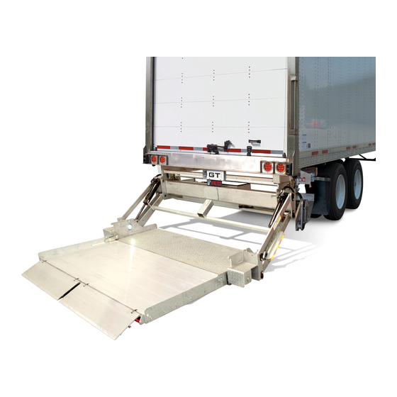
Installation Manual
BZ-33, BZ-44
3300 lb. & 4400 lb. Capacity Cantilever Liftgates
Last Change
Date
03/2018
Waltco Lift Corp.
Corporate Office United State
285 Northeast Ave.
Tallmadge, OH 44278
P: 330.633.9191
F: 330.633.1418
EO:10338 Rev 02
10-2017
Pages
17-23
REVISED SCHEMATICS
Waltco Lift Corp.
United States
620 S Hambledon Ave.
City of Industry, CA 91744
P: 626.964.0990
F: 626.964.0149
www.waltco.com
parts@waltco.com
Description
800.411.5685
Phone:
800.411.5684
Fax:
Gen 7
GR02912
Waltco Lift Inc.
Canada
90 North Queen St.
Etobicoke, ON M8Z 2C5
P: 888-343.4550
80117221
Advertisement
Table of Contents

Related Manuals for Waltco Lift BZ-33

Summary of Contents for Waltco Lift BZ-33
- Page 1 800.411.5685 Phone: parts@waltco.com 800.411.5684 Fax: Installation Manual BZ-33, BZ-44 Gen 7 3300 lb. & 4400 lb. Capacity Cantilever Liftgates GR02912 Last Change Date Pages Description 03/2018 17-23 REVISED SCHEMATICS Waltco Lift Corp. Waltco Lift Corp. Waltco Lift Inc. Corporate Office United State...
-
Page 2: Table Of Contents
Table of Contents Improper installation of this liftgate could result in severe personal injury or death. Read and understand the contents of these instructions before proceeding. When installed, this liftgate must not alter or prevent vehicle compliance to any existing state or federal standards. Each chassis manufacturer’s recommendations should be consulted for compliance. -
Page 3: Introduction
It is important that every vehicle that has a WALTCO Liftgate have legible DECALS clearly posted on the vehicle and an OWNER’S MANUAL in the vehicle at all times as a guide for proper operation and maintenance. Additional DECALS and OWNER’S MANUALS can be obtained from WALTCO LIFT CORP. 80101388 Rev 03 EO 7820 page 3... -
Page 4: Safety Information
Chapter 1 Safety Information WARNING Read, understand, and follow all of the warning listed below. Failure to follow these warning could result in severe personal injury or death. Read and understand the Owner’s Manual, all decals and warning on liftgate before operating liftgate. •... - Page 5 Chapter 1 Safety Information Liftgates with Tilt Function Proper use of the Control Switches is of extreme importance. • Improper use of Tilt Switch could cause load to fall from the Platform or damage the liftgate. • Platform should be in a generally horizontal position when raising or lowering with a load. •...
-
Page 6: Liftgate Terminology
Chapter 2 Liftgate Terminology 1. Platform 2. Mount Tube 3. Pump and Motor Tray 4. Lift Arm 5. Bumper 6. Lift Cylinder 7. Tilt Cylinder 8. Upper Lift Arm Pin 9. Lower Lift Arm Pin 10. Upper Lift Cylinder Pin 11. - Page 7 Chapter 2 Liftgate Terminology Explanation of Specification Tag BZ33 G7 Level Lift 3300 lbs. BZ44 G7 Level Lift 4400 lbs. RATED CAPACITY MODEL NUMBER Based on an evenly distributed load on the platform flat surface. SERIAL NUMBER of liftgate. To be used DATE OF when ordering parts or MANUFACTURE...
-
Page 8: Basic Mounting Requirements
Chapter 3 Basic Mounting Requirements DETERMINE MOUNTING DIMENSIONS Determine bed height. Measure from top of vehicle floor down to ground. MOUNT TUBE 1-3/4” CLEARANCE FLOOR LEVEL Verify which length arms liftgate has. SILL DEPTH “A”- DIMENSION NOTE: All dimensions when vehicle unloaded on horizontal surface. - Page 9 Mount tube must be installed at least 1-5/8” below vehicle chassis to allow room for mounting brackets. 1-5/8” GR00496 INSTALLATION DIMENSIONS NOTE: B height dimensions are the maximums for the unloaded vehicle. BZ-33/44 Short arm, 29-1/2" Optional A-Dimension Bed Height Maximum sill depth Mount tube clearance 15.5 33.00...
-
Page 10: Liftgate Installation
Chapter 4 Liftgate Installation PREPARATION OF BODY Remove all obstructions that will interfere with liftgate operation. Dock bumpers Trailer hitches Other projections GR00511 NOTCH REAR SILL Mark a witness line at center of rear sill. This line will be used for centering the liftgate later. If rear sill is deeper than the “Max Sill Depth”, as indicated in the Mounting Requirements, notch as shown. - Page 11 Chapter 4 Liftgate Installation REINFORCE REAR SILL AREA If necessary extend chassis frame back to rear sill. Add bar or angle to cap off frame and tie it in with rear sill. Add a tie strap on the side of the chassis frame to tie it together with the body long member.
- Page 12 Chapter 4 Liftgate Installation Locate and tack-weld the mounting jig to rear sill of body. Align the centerline marks of the jig with mark on sill. Verify the 1-3/8” and 3-1/8” dimensions. Note: For vehicles with swing doors, refer to section in back of manual “For Vehicles with Swing Doors”.
- Page 13 Chapter 4 Liftgate Installation Check that lift arm assembly pivots freely on pivot pins in mount frame. If necessary, loosen nuts on pivot pins indicated. GR00061 Position liftgate mount frame on a floor jack or other type of lifting device. Rotate lift arms up to the mounting jig.
- Page 14 Chapter 4 Liftgate Installation Jack mount frame up to the proper “A” Dimension. Refer to the Mounting Requirements in this manual. Note: Use the smallest “A” Dimension per the chart, this insures the greatest ground clearance. Important: Top of mount tube is not to contact the vehicle chassis frame.
- Page 15 Chapter 4 Liftgate Installation MOUNT PLATES BOLTED TO CHASSIS FRAME INSTALL ENDPLATE Bolt mount plates to chassis frame and install endplates AS SHOWN onto mount plates. Using 1/2” bolts and square washers, bolt mount plates to vehicle chassis frame. Install endplates as shown with provided nuts and washers and torque to 85 ft.
-
Page 16: Electrical Installation
Chapter 4 Liftgate Installation A 150 amp circuit breaker is to be installed on the main power cable running from the battery compartment**. This acts to protect the electrical of fire. systems from overloading and the risk page 16... -
Page 17: Electrical Schematics
Chapter 4 Liftgate Installation Electric and Hydraulic Diagram page 17... - Page 18 Chapter 4 Liftgate Installation Electric and Hydraulic Diagram (with Auto-tilt) page 18...
- Page 19 Chapter 4 Liftgate Installation 3-Button Control Unit (Permanent) Note: The permanent switch control box comes with a resistor heater wire. It is recommended that this wire be removed and not used. Install the main gate control in control bank 1. NOTE: For units without a 2 hand switch, connect a jumper between C and 2H1 in control bank 1.
- Page 20 Chapter 4 Liftgate Installation For units without an inside of deck mounted angle sensor, verify there is a Green or Red jumper wire installed between “Sensor Power” and Di 3 terminals on circuit board. Cable lead-through In order to be able to install/remove/adjust the cables in the cable grommet, its protective cover must be removed and the five screws loosened.
- Page 21 Chapter 4 Liftgate Installation Hydraulic unit and control card The lift’s hydraulic unit and its control card are installed inside the lift’s frame. For access during installation, service and repair, for example, the protective cap needs to be dismantled and the hydraulic unit pulled a little way out of the frame.
- Page 22 Chapter 4 Liftgate Installation Connecting cabin switch and open platform alarm Tiltcylinder NOTE. Cab Shut-Off Switch Bronze tab connects Sensor Power Not in use to ground Outputs Center Tab connects to card NC 60bar Pump unit Ctrl 1 Outside "silver" tab IN OUT connects to power.
- Page 23 Chapter 4 Liftgate Installation Functional schematic drawing BZ Gen 7 (confi g 14) Function Input sig- Input Output signal Comment Control Illustration signal device high low (0V) 1º Safety, the plat- Di2+Di3+ form is completely Ctrl 1 1 C+E+2H U1+U3+U5 raised and does Ctrl 2 not move.
- Page 24 Chapter 4 Liftgate Installation Function Input sig- Input Output signal Comment Control Illustration signal device high low (0V) Ctrl 1 45º Ctrl 2 Tilt down 1 C+E+Di3* U0+U1+U3+U5 Ctrl 3 Ctrl 4 Ctrl 6 -10º Ctrl 1 Ctrl 2 1 B+Di2 U0+U3 Autotilt up Ctrl 3...
- Page 25 Chapter 4 Liftgate Installation Restriction of use of control device Image 1. Use of radio control device limited by the platform angle. Sensor Name Position Function Description (standard) Lift arm Angle sensor For autotilt, safety function. Platform Angle sensor For autotilt, platform angle. There is some trimming allowance Module for the bracket in the platform in order to facilitate adjustment of the platform’s autotilt angle.
- Page 26 Chapter 4 Liftgate Installation Connection unit Power save mode If the control card is not used for approx. 5 minutes, it goes into power save mode. Press any control button for approx. 0.5 seconds to “wake up” the control card again. Operating information All the lift’s functions are controlled and monitored through the control card, which is equipped with an alphanumerical display with a fl...
-
Page 27: Electrical Trouble Shooting
Chapter 4 Liftgate Installation Information codes Codes are shown on the display in a sequence. First a letter for identifi cation of information, fol- lowed by fi gures or segments for further information and then ending with a pause: When the CS (cabin switch) is switched on, the current program confi guration (P) is displayed fi... - Page 28 Chapter 4 Liftgate Installation Information codes Code Code Identifi cation Code 1 Information Other 00–99 Cancelled confi guration (Program Dividers confi guration) 12/24 Number of volts detected 01–99 Version number Software version Fixed light (1-6) displays active control 1-6 (Fixed light) device during operation.
- Page 29 Chapter 4 Liftgate Installation Fault codes If a fault arises, the fault code is shown in the display in the form of a letter for identifying the fault, followed by numbers and/or number segments for further information, followed by sensor indica- tion (C) in accordance with the previous page.
- Page 30 Chapter 4 Liftgate Installation Fault codes Code Identifi cation Code 1 Code 2 Information Other 1-7 U 0 - U 7 , d i s - played only af- Output short-circuit- ter the respec- Which output has short-circuited/ ed/high current t i v e o u t p u t / has high current.
- Page 31 Chapter 4 Liftgate Installation Supply voltage The illustrations below show the desired supply voltage for 12V and 24V systems. Specifi ed voltage refers to voltage when the lift is operated. See also section "16.2 Maximum power consumption - Minimum recommended conductor cross sectional area" on page 12. The lift is not working.
-
Page 32: Battery Connection
Chapter 4 Liftgate Installation INSTALLATION OF COMPRESSION TERMINALS Heat shrinkable tubing Before installation Cut power cable (red) and ground cable (black) to length 7/8” to 1” and install compression terminals. Strip 7/8” to 1” of insulation from end of cable. Slide heat shrinkable tubing onto cable. - Page 33 Chapter 4 Liftgate Installation INSTALL TERMINALS TO BATTERY Copper terminal Link 150 Amp (10099500) connected Connect red 2GA cable to red quick connector behind Circuit direct to Battery Post main frame. Breaker and Circuit Breaker Positive (Red) Route positive battery cable from lift unit to battery box. Battery Cable from Connect the end of the battery cable from the liftgate to liftgate...
-
Page 34: Fill Reservoir
Chapter 4 Liftgate Installation REMOVE TRANSPORT PLUG BREATHER PLUG Replace transport plug from oil tank with breather plug. Check oil level, oil level should be ½” below top of oil tank. Add oil if needed. Do not over fill. GR03015 Recommended Fluids Fill reservoir Temperature Range... -
Page 35: Platform Install
Chapter 4 Liftgate Installation INSTALL REAR SILL EXTENSION Cut extension so it will extend to within ½” of each side to vehicle body. Position and weld extension, centered on door opening. Note: If the full door seal kit, or flip-up door option are to be used, they will use a different type of sill extension. -
Page 36: Up-Stop
Chapter 4 Liftgate Installation INSTALLATION OF TILT CYLINDERS Pin tang to fully Manually Pivot the Tilt Cylinders into position. engage in hinge (middle plate) Extend or Retract the Tilt Cylinders as needed, to align rod eye with lower pivot holes in Platform Hinges, by using the Raise and Tilt or Lower and Tilt switches. - Page 37 Chapter 4 Liftgate Installation WELDING, CUTTING AND GRINDING Before doing any metal work: Pull pump unit out from main frame and cover with non flammable material. PULL PUMP UNIT OUT Cover piston rods with non flammable material. Welding, torching or grinding can damage cylinders, hoses or electrical system.
- Page 38 Chapter 4 Liftgate Installation INSTALL UP STOPS Liftarms movement up must be limited mechanically. Rear sill is not strong enough to withstand forces from liftgate. Use 2” x 2” x .25 tube (or similar) to limit up movement of lift arm as shown. Material for up stops is not provided.
-
Page 39: Platform Tilt/Cylinder Adjustment
Chapter 4 Liftgate Installation ELECTRONIC AUTOMATIC TILT For units equipped with Auto-tilt, install the angle sensor. The angle sensor should be positioned on the lift arm as shown. Note: When installing on the left arm, the sensor’s cable input must be facing upwards. When installing on the right arm, the sensor’s cable must be facing downward. - Page 40 Chapter 4 Liftgate Installation IMPORTANT! Tilt up the platform until it closes without tilting over 90° . The tilt cylinders should be fully extended. If platform will tilt over 90° tilt cylinders must be adjusted in order to prevent damage of over tilting. Cylinder adjustments should be made when the cylinders are fully pressurized.
- Page 41 Chapter 4 Liftgate Installation ADJUSTING TILT DOWN ANGLE Note: To obtain the correct tilt down function, it is necessary to follow the previous instructions which ensure a correct 90° tilt angle up against the truck’s body. Cycle the lift up until it reaches floor level. GR02829 Loosen the cylinder ring’s lock screw (1).
- Page 42 Chapter 4 Liftgate Installation PLATFORM RUBBER STOPS PLATFORM If the vehicle is not equipped with at least side seals, rubber stops for the platform must be installed on the corner post of the body at a height of 2/3’s the height of the closed liftgate platform on both corner posts Install rubber stops as shown and adjust tilt cylinders so that the platform firmly contacts the stops when fully...
-
Page 43: Bumper
Chapter 4 Liftgate Installation INSTALLATION OF 3-PIECE BUMPER Install (3) piece bumper as shown. NOTE: All (3) pieces need to be installed! Bumper bars have three height adjustment possibilities; all bumper bars must be installed to same height position. Every bumper bar must be secured with three bolts and lock nuts (supplied). - Page 44 Chapter 4 Liftgate Installation BRIDGE FABRICATION A bridge may be fabricated approximately as shown to reduce the gap between the platform and sill in the previous step. The bridge must be notched for door hardware. It must also be wide enough and constructed such that its strength is not compromised by the notching.
-
Page 45: Check Operation
Chapter 4 Liftgate Installation FINAL INSTALLATION OF BRIDGE Weld bridge to lift arms 100% as shown. GR00114 LOADING AREA Bridge will pivot over back of platform when lowered. Mark back of platform as a no loading area as necessary. GR00115 OPERATION CHECK •... - Page 46 Chapter 4 Liftgate Installation TO RAISE AND LOWER PLATFORM IN LOADING POSITION. • Push raise switch to raise platform • Push lower switch to lower platform GR00107 TO TILT PLATFORM UP AND DOWN. • First push and hold tilt switch, then simultaneously push raise switch to tilt platform up.
-
Page 47: Placement Of Decals
One (1) of the following three (2) decals is to be positioned in a conspicuous place near the control PLACE DECALS IN THIS AREA switches as shown. 80101415 – BZ-33 Capacity Decal 80101416 – BZ-44 Capacity Decal If your liftgate is equipped with dual controls, an additional Safety Instruction... - Page 48 DECALS HERE One (1) of the following three (2) decals is to be positioned in a conspicuous place on the bottom of the platform as shown 80101415 – BZ-33 Capacity Decal 80101416 – BZ-44 Capacity Decal CAPACITY DECAL HERE GR00511...
- Page 49 Chapter 5 Placement of Decals SAFETY TAPE AND FLAGS Tape (Z20290) is to be placed on the sides of platform so it is visible from the side. Tape 9” 9” 9” Locate corner flag mount brackets (Z20273), one on Flag each side of platform and drill (3) holes per bracket into platform as shown.
-
Page 50: Lubrication Instructions
Chapter 6 Lubrication LUBRICATION INSTRUCTIONS 12 grease fittings should be lubricated with a grease gun per the lubrication schedule below. Note: All fittings should be greased with the platform in the stored position. SUGGESTED MINIMUM LUBRICATION SCHEDULE (IN DAYS) Monthly Cycles Light Duty Med. -
Page 51: Final Inspection
Chapter 7 Final Inspection List IMPORTANT All of the following items are to be checked and verified before installation is complete. A. All welds are properly done. B. All bolts, nuts, and screws are tight and torqued to the proper specification. C. -
Page 52: Optional Kit Instructions: Aux Battery Kit (Truck)
BATTERY KIT INSTALLATIONS 80101387 DETERMINE BATTERY AND PUMP LOCATION, AND CABLE ROUTING Determine where pump unit and battery box will be located. Make certain hydraulic hoses supplied will reach pump. Your installation may use only one cable supplied with liftgate, or, it may also use a cable supplied with the trailer kit. - Page 53 BATTERY KIT INSTALLATIONS 80101387 BATTERY AND PUMP BOX INSTALLATION BODY CROSSMEMBERS Locate battery box and pump box in a suitable location under the vehicle body (refer to previous page.) Weld hanger channels to body crossmembers. HANGER CHANNELS PUMP BOX BATTERY BOX Hint: To save space, hanger channels can be cut down and boxes moved closer together as shown.
- Page 54 BATTERY KIT INSTALLATIONS 80101387 INSTALLATION OF TERMINAL LUG Heat shrinkable tubing Strip 7/8” to 1” of insulation from end of cable. before installation Slide heat shrinkable tubing onto cable. 7/8” to 1” Insert bare wire into compression nut until it seats. NOTE: Be sure to use correct compression nut, use 2 gauge nut for 2 gauge cable, use 0 Compression Nut...
- Page 55 BATTERY KIT INSTALLATIONS 80101387 INSTALLATION OF SOCKET Drill 1-3/4” hole in nose of trailer for trailer socket. Mount socket to trailer with bolts and nuts provided. Trailer Socket Attach cable to back of socket with bolt provided. Apply a generous amount of Dielectric Grease over cable terminal.
-
Page 56: Kit #80001066
BATTERY KIT INSTALLATIONS 80101387 INSTALLATION OF CIRCUIT BREAKER(S) Cable supplied Auxiliary batteries on a truck will require circuit breakers with Liftgate at both the auxiliary batteries and the vehicle batteries. Locate and mount 150 Amp circuit breaker directly to batteries using copper terminal link supplied. See below Circuit breaker must be mounted to give good protection For detail... -
Page 57: Full Door Seal Kit
________________________________________________________________________________ FULL-DOOR SEAL KIT INSTALLATION Rubber Air Foil 75089937 80101285 Double Rail 75089936 Rubber Seal 75089960 Rail 75089911 Rubber Sill 75089912 Note: Rubber Seals & Air Foils are cut back in details for clarity 80101285 EO4662 Rev 02 1-2002 page 57... - Page 58 INSTALLATION OF FULL-DOOR SEAL KIT Note: The Side Rubber Seals and Air Foils must be installed on the rear corner posts of vehicle before the Top Seal and Air Foil is installed. 1. With the Platform in the stored position, find the location of the Top Double Rail according to Figure 1.
- Page 59 3. Cut the Top & Side Double Rails, Top & Side Rubber Seals, and Top & Side Air Foils at 45° angles as shown. Fig. 2 4. With the Platform open, position the Side Double Rails against the outer side of the Locking Lug as shown below.
- Page 60 5. Insert the Rubber Seal & Air Foil down into Side Double Rails from the top as shown. Rubber Seal Air Foil Fig. 4 6. Before inserting the Rubber Seal and Air Foil into the Top Double Rail, drill holes in the Top Double Rail and body header.
- Page 61 Add silicone caulk to seal gaps between tracks and vehicle body. page 61...
-
Page 62: Kit #80000573 Cycle Counter Kit
Cycle Counter Installation Instructions • IMPORTANT! Disconnect battery power supply. • Review these instructions before beginning. Locate a position on your liftgate for the cycle counter. Be certain that location will not interfere with liftgate operation and is in a relatively protected area. -
Page 63: How To Order Parts
THEN INCLUDE THE FOLLOWING INFORMATION: 4. PART NUMBERS 5. DESCRIPTION 6. QUANTITY REQUIRED ________________________________________________________________ MAIL, E-MAIL OR PHONE YOUR REQUEST TO: Waltco Lift Corp 285 Northeast Avenue Tallmadge, OH 44278 1-800-411-5685 FAX: 1-800-411-5684 E-MAIL: parts@waltco.com ALL PARTS ARE F.O.B. FROM THE SHIPPING FACTORY... - Page 64 OWNER’S MANUAL in the vehicle at all times as a guide for proper operation and maintenance. Additional WARNING DECALS, OPERATION DECALS and OWNER’S MANUALS can be obtained from WALTCO LIFT CORP. ____________________ NOTE: When ordering, give model and serial number of the liftgate.
- Page 65 This page left intentionally blank. page 65...
- Page 66 IMPORTANT WARNING Improper operation and maintenance of this liftgate could result in severe personal injury or death. Read and understand the contents of this manual and all warning and operation decals before operating and/or performing maintenance on this liftgate. For SAFETY information on this liftgate see Chapter 1 of this manual 80101520 EO7820...
Need help?
Do you have a question about the BZ-33 and is the answer not in the manual?
Questions and answers