Table of Contents
Advertisement
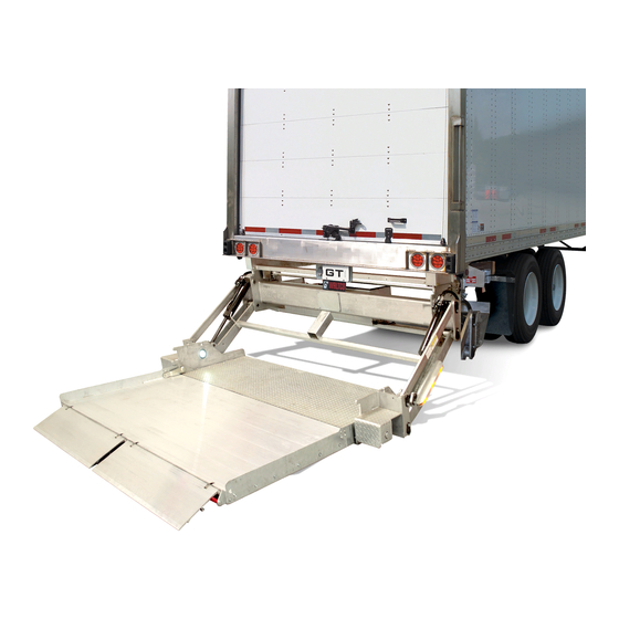
BZ-33, BZ-44
3300 lb. & 4400 lb. Capacity Cantilever Liftgates
Last Change
Date
03/20/2018
Waltco Lift Corp.
Corporate Office United State
285 Northeast Ave.
Tallmadge, OH 44278
P: 330.633.9191
F: 330.633.1418
EO:10338 Rev 02
03/2018
sales@waltco.com
Owner's Manual
Pages
23-25
REVISED ELECTRICAL SCHEMATICS
Waltco Lift Corp.
United States
620 S Hambledon Ave.
City of Industry, CA 91744
P: 626.964.0990
F: 626.964.0149
www.waltco.com
Description
800.211.3074
Phone:
800.211.3075
Fax:
Gen 7
GR02912
Waltco Lift Inc.
Canada
90 North Queen St.
Etobicoke, ON M8Z 2C5
P: 888.343.4550
80117222
Advertisement
Table of Contents

Related Manuals for Waltco Lift BZ-33

Summary of Contents for Waltco Lift BZ-33
- Page 1 800.211.3074 Phone: sales@waltco.com 800.211.3075 Fax: Owner’s Manual BZ-33, BZ-44 Gen 7 3300 lb. & 4400 lb. Capacity Cantilever Liftgates GR02912 Last Change Date Pages Description 03/20/2018 23-25 REVISED ELECTRICAL SCHEMATICS Waltco Lift Corp. Waltco Lift Corp. Waltco Lift Inc.
-
Page 2: Table Of Contents
Table of Contents Improper operation and maintenance of this liftgate could result in severe personal injury or death. Read and understand the contents of this manual and all warning and operation decals before operating and/or performing maintenance on this liftgate. Introduction ........................ -
Page 3: Introduction
It is important that every vehicle that has a WALTCO Liftgate have legible DECALS clearly posted on the vehicle and an OWNER’S MANUAL in the vehicle at all times as a guide for proper operation and maintenance. Additional DECALS and OWNER’S MANUALS can be obtained from WALTCO LIFT CORP. 80101388 Rev 03 EO 7820 page 3... -
Page 4: Safety Information
Chapter 1 Safety Information WARNING Read, understand, and follow all of the warning listed below. Failure to follow these warning could result in severe personal injury or death. Read and understand the Owner’s Manual, all decals and warning on liftgate before operating liftgate. •... - Page 5 Chapter 1 Safety Information Liftgates with Tilt Function Proper use of the Control Switches is of extreme importance. • Improper use of Tilt Switch could cause load to fall from the Platform or damage the liftgate. • Platform should be in a generally horizontal position when raising or lowering with a load. •...
-
Page 6: Warranty
Diagnosis and troubleshooting time are included in the flat rate labor times. Warranty and technical information is available from WALTCO’s toll free customer service lines from 8:00 a.m. to 5:00 p.m. EST. Waltco Lift Corp 285 Northeast Ave, Box 354, Tallmadge, OH 44278 1-800-211-3074, 330-633-9191 Please visit our websites: http://www.waltco.com... -
Page 7: Liftgate Terminology
Chapter 2 Liftgate Terminology 1. Platform 2. Mount Tube 3. Pump and Motor Tray 4. Lift Arm 5. Bumper 6. Lift Cylinder 7. Tilt Cylinder 8. Upper Lift Arm Pin 9. Lower Lift Arm Pin 10. Upper Lift Cylinder Pin 11. - Page 8 Chapter 2 Liftgate Terminology Explanation of Specification Tag BZ33 G7 Level Lift 3300 lbs. BZ44 G7 Level Lift 4400 lbs. RATED CAPACITY MODEL NUMBER Based on an evenly distributed load on the platform flat surface. SERIAL NUMBER of liftgate. To be used DATE OF when ordering parts or MANUFACTURE...
-
Page 9: Operation Instructions
Chapter 3 Operations Instructions IMPORTANT Understand these instructions before operating liftgate When in transit, platform is to be closed When not in use, electrical shut off switch is to be off. In any tilt position, the attitude of the platform may vary from level while raising or lowering the platform. Make certain area in which platform will open and close is clear before opening or closing, and at all times during operation. - Page 10 Chapter 3 Operations Instructions TO OPEN PLATFORM RAISE Turn shut-off switch on (located in cab or near controls). TILT Always make certain area in which platform will LOWER open is clear. Push and hold tilt switch then lower switch to unfold platform.
- Page 11 Chapter 3 Operations Instructions IMPORTANT! To avoid vehicle or liftgate damage, never attempt to close platform until platform is first at bed level. GR00705 SECURE PLATFORM FOR TRANSIT Close platform. Turn shut-off switch off. KEY SHUT- OFF SWITCH CAUTION! Keep hands away from pinch points. IMPORTANT! Electrical shut-off switch is a safety device and must be CAB SHUT-OFF...
- Page 12 Tilting platform may cause an unstable load to roll off if unattended. GR00704 BZ-33 Only If the load is centered no farther than 30” out from the vehicle rear sill, the maximum capacity is 3300 lbs. As the load is centered farther out on the platform, the maximum capacity is reduced, as shown.
- Page 13 Chapter 3 Operations Instructions LOADING OF PLATFORM CARGO AS PLATFORM IS Before loading, tilt platform slightly upwards to POSIOTIONED TOO LOWERED CARGO compensate for load. CLOSE TO REAR HITS REAR SILL SILL Always load as close to the center of the platform and as close to the vehicle as possible.
- Page 14 Chapter 3 Operations Instructions Locate Drive Over Operation Decal attached to vehicle for information on maximum drive over capacity. Decal 80101499 will show max. capacity of 5,500 lbs. Decal 80101330 will show max. capacity of 10,000 lbs. Drive Over Operation Decal 80101499 or 80101330 would be attached in this area.
-
Page 15: Preventive Maintenance
Chapter 4 Preventive Maintenance Waltco recommends that the BZ-Series liftgate be inspected at 6 month or 3000 cycle intervals to help assure proper function and operation of the liftgate. Note: Photocopy the following PM Checklist to help keep track of periodic maintenance on the liftgate. Keep completed form with maintenance records. - Page 16 Chapter 4 Preventive Maintenance MONTHLY INSPECTION Operate the liftgate throughout its entire operational cycle. Check for: Damage to lifting structure such as bent or • • • • distorted members or cracked welds. Bent or distorted cylinder pins or damaged •...
- Page 17 Chapter 4 Preventive Maintenance Check oil level Lower platform to the ground and tilt down to the BREATHER PLUG ground. Open breather plug. Oil should be ½” from top of reservoir. Fill as may be required. Obey oil recommendations. GR03015 BLEEDING CYLINDERS Lift cylinders: Fully lower platform a few times.
- Page 18 Chapter 4 Preventive Maintenance SEMI ANNUAL INSPECTION Remove cover to Inspect power motor: check brushes and Disconnect battery cable. clean out motor • Remove end cover. • Examine armature brushes for wear (motor • should be replaced if brushes are less than 1/8” long).
-
Page 19: Placement Of Decals
One (1) of the following three (2) decals is to be positioned in a conspicuous place near the control PLACE DECALS IN THIS AREA switches as shown. 80101415 – BZ-33 Capacity Decal 80101416 – BZ-44 Capacity Decal If your liftgate is equipped with dual controls, an additional Safety Instruction... - Page 20 DECALS HERE One (1) of the following three (2) decals is to be positioned in a conspicuous place on the bottom of the platform as shown 80101415 – BZ-33 Capacity Decal 80101416 – BZ-44 Capacity Decal CAPACITY DECAL HERE GR00511...
- Page 21 Chapter 5 Placement of Decals SAFETY TAPE AND FLAGS Tape (Z20290) is to be placed on the sides of platform so it is visible from the side. Tape 9” 9” 9” Locate corner flag mount brackets (Z20273), one on Flag each side of platform and drill (3) holes per bracket into platform as shown.
-
Page 22: Lubrication
Chapter 6 Lubrication LUBRICATION INSTRUCTIONS 12 grease fittings should be lubricated with a grease gun per the lubrication schedule below. Note: All fittings should be greased with the platform in the stored position. SUGGESTED MINIMUM LUBRICATION SCHEDULE (IN DAYS) Monthly Cycles Light Duty Med. -
Page 23: Schematics
Electrical Information Electric and Hydraulic Diagram page 23... - Page 24 Electrical Information Electric and Hydraulic Diagram (with Auto-tilt) page 24...
- Page 25 Electrical Information 3-Button Control Unit (Permanent) Note: The permanent switch control box comes with a resistor heater wire. It is recommended that this wire be removed and not used. Install the main gate control in control bank 1. NOTE: For units without a 2 hand switch, connect a jumper between C and 2H1 in control bank 1.
- Page 26 Electrical Information For units without an inside of deck mounted angle sensor, verify there is a Green or Red jumper wire installed between “Sensor Power” and Di 3 terminals on circuit board. Cable lead-through In order to be able to install/remove/adjust the cables in the cable grommet, its protective cover must be removed and the five screws loosened.
- Page 27 Electrical Information Hydraulic unit and control card The lift’s hydraulic unit and its control card are installed inside the lift’s frame. For access during installation, service and repair, for example, the protective cap needs to be dismantled and the hydraulic unit pulled a little way out of the frame.
- Page 28 Electrical Information Connecting cabin switch and open platform alarm Tiltcylinder NOTE. Cab Shut-Off Switch Bronze tab connects Sensor Power Not in use to ground Outputs Center Tab connects to card NC 60bar Pump unit Ctrl 1 Outside "silver" tab IN OUT connects to power.
-
Page 29: Electrical Trouble Shooting
Electrical Information Functional schematic drawing BZ Gen 7 (confi g 14) Function Input sig- Input Output signal Comment Control Illustration signal device high low (0V) 1º Safety, the plat- Di2+Di3+ form is completely Ctrl 1 1 C+E+2H U1+U3+U5 raised and does Ctrl 2 not move. - Page 30 Electrical Information Function Input sig- Input Output signal Comment Control Illustration signal device high low (0V) Ctrl 1 45º Ctrl 2 Tilt down 1 C+E+Di3* U0+U1+U3+U5 Ctrl 3 Ctrl 4 Ctrl 6 -10º Ctrl 1 Ctrl 2 1 B+Di2 U0+U3 Autotilt up Ctrl 3 Ctrl 4...
- Page 31 Electrical Information Restriction of use of control device Image 1. Use of radio control device limited by the platform angle. Sensor Name Position Function Description (standard) Lift arm Angle sensor For autotilt, safety function. Platform Angle sensor For autotilt, platform angle. There is some trimming allowance Module for the bracket in the platform in order to facilitate adjustment of the platform’s autotilt angle.
- Page 32 Electrical Information Connection unit Power save mode If the control card is not used for approx. 5 minutes, it goes into power save mode. Press any control button for approx. 0.5 seconds to “wake up” the control card again. Operating information All the lift’s functions are controlled and monitored through the control card, which is equipped with an alphanumerical display with a fl...
- Page 33 Electrical Information Information codes Codes are shown on the display in a sequence. First a letter for identifi cation of information, fol- lowed by fi gures or segments for further information and then ending with a pause: When the CS (cabin switch) is switched on, the current program confi guration (P) is displayed fi...
- Page 34 Electrical Information Information codes Code Code Identifi cation Code 1 Information Other 00–99 Cancelled confi guration (Program Dividers confi guration) 12/24 Number of volts detected 01–99 Version number Software version Fixed light (1-6) displays active control 1-6 (Fixed light) device during operation. Active control device while operating Segments B, C, E or X are illuminated...
- Page 35 Electrical Information Fault codes If a fault arises, the fault code is shown in the display in the form of a letter for identifying the fault, followed by numbers and/or number segments for further information, followed by sensor indica- tion (C) in accordance with the previous page. In fault codes E, F and U, the numbers (1-9) show which control device/output the fault code refers to.
- Page 36 Electrical Information Fault codes Code Identifi cation Code 1 Code 2 Information Other 1-7 U 0 - U 7 , d i s - played only af- Output short-circuit- ter the respec- Which output has short-circuited/ ed/high current t i v e o u t p u t / has high current.
- Page 37 Electrical Information Supply voltage The illustrations below show the desired supply voltage for 12V and 24V systems. Specifi ed voltage refers to voltage when the lift is operated. See also section "16.2 Maximum power consumption - Minimum recommended conductor cross sectional area" on page 12. The lift is not working.
-
Page 38: How To Order Parts
THEN INCLUDE THE FOLLOWING INFORMATION: 4. PART NUMBERS 5. DESCRIPTION 6. QUANTITY REQUIRED ________________________________________________________________ MAIL, E-MAIL OR PHONE YOUR REQUEST TO: Waltco Lift Corp 285 Northeast Avenue Tallmadge, OH 44278 1-800-411-5685 FAX: 1-800-411-5684 E-MAIL: parts@waltco.com ALL PARTS ARE F.O.B. FROM THE SHIPPING FACTORY... - Page 39 OWNER’S MANUAL in the vehicle at all times as a guide for proper operation and maintenance. Additional WARNING DECALS, OPERATION DECALS and OWNER’S MANUALS can be obtained from WALTCO LIFT CORP. ____________________ NOTE: When ordering, give model and serial number of the liftgate.
- Page 40 IMPORTANT KEEP THIS OWNER’S MANUAL IN THE VEHICLE WARNING Improper operation and maintenance of this liftgate could result in severe personal injury or death. Read and understand the contents of this manual and all warning and operation decals before operating and/or performing maintenance on this liftgate.
Need help?
Do you have a question about the BZ-33 and is the answer not in the manual?
Questions and answers