Table of Contents
Advertisement
Advertisement
Table of Contents

Related Manuals for Mitsubishi Mahindra GX3600


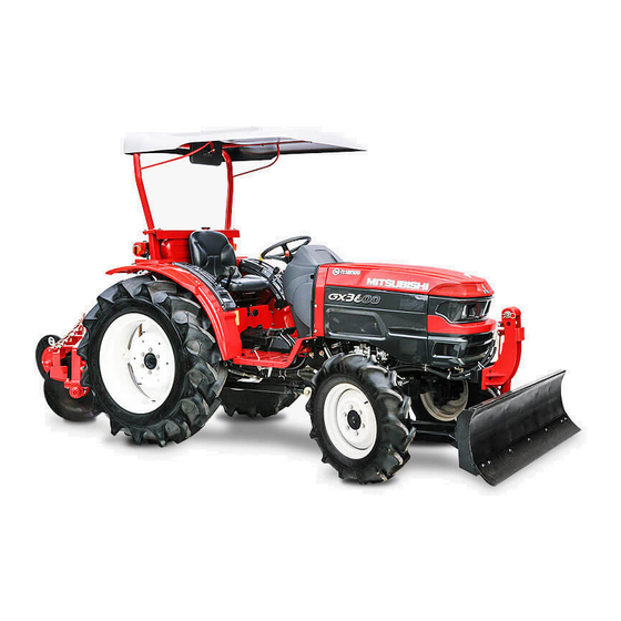
Summary of Contents for Mitsubishi Mahindra GX3600
- Page 1 MITSUBISHI TRACTOR SERVICE MANUAL...
-
Page 3: Table Of Contents
CONTENTS SECTION - 1 : SAFETY, GENERAL INFORMATION AND STANDARD TORQUE SPECIFICATIONS 1. SAFETY ......................03 2. GENERAL INFORMATION ................. 17 3. STANDARD BOLT TORQUES ................21 SECTION - 2 : SPECIFICATIONS 1. GENERAL SPECIFICATIONS ................27 2. GEAR RATIO ...................... 30 3. -
Page 5: Section - 1 : Safety, General Information And Standard Torque Specifications
SECTION -1 SAFETY, GENERAL INFORMATION AND STANDARD TORQUE SPECIFICATIONS... -
Page 7: Safety
SAFETY, GENERAL INFORMATION AND STANDARD TORQUE SPECIFICATIONS SAFETY This symbol means ATTENTION! BECOME ALERT! YOUR SAFETY IS INVOLVED. The message that follows the symbol contains important information about safety carefully read the message. Make sure you fully understand the causes of possible injury or death. To prevent injury always follow the Warning, Caution and Danger notes in this section and throughout the manual. - Page 8 SAFETY, GENERAL INFORMATION AND STANDARD TORQUE SPECIFICATIONS CAUTION: When servicing or repairing the WARNING: Always use heat protective gloves machine. Keep the shop floor and operator's when handling heated parts. compartment and steps free of oil, water, grease, tools etc. CAU T I ON : L o w er all attachme nts t o th e Use the oil absorbing material and or shop ground or use stands to safely support the...
- Page 9 SAFETY, GENERAL INFORMATION AND STANDARD TORQUE SPECIFICATIONS...
- Page 10 SAFETY, GENERAL INFORMATION AND STANDARD TORQUE SPECIFICATIONS...
- Page 11 SAFETY, GENERAL INFORMATION AND STANDARD TORQUE SPECIFICATIONS...
- Page 12 SAFETY, GENERAL INFORMATION AND STANDARD TORQUE SPECIFICATIONS...
- Page 13 SAFETY, GENERAL INFORMATION AND STANDARD TORQUE SPECIFICATIONS...
- Page 14 SAFETY, GENERAL INFORMATION AND STANDARD TORQUE SPECIFICATIONS...
- Page 15 SAFETY, GENERAL INFORMATION AND STANDARD TORQUE SPECIFICATIONS...
- Page 16 SAFETY, GENERAL INFORMATION AND STANDARD TORQUE SPECIFICATIONS...
- Page 17 SAFETY, GENERAL INFORMATION AND STANDARD TORQUE SPECIFICATIONS...
- Page 18 SAFETY, GENERAL INFORMATION AND STANDARD TORQUE SPECIFICATIONS...
- Page 19 SAFETY, GENERAL INFORMATION AND STANDARD TORQUE SPECIFICATIONS...
- Page 20 SAFETY, GENERAL INFORMATION AND STANDARD TORQUE SPECIFICATIONS...
-
Page 21: General Information
SAFETY, GENERAL INFORMATION AND STANDARD TORQUE SPECIFICATIONS GENERAL INFORMATION... - Page 22 SAFETY, GENERAL INFORMATION AND STANDARD TORQUE SPECIFICATIONS...
- Page 23 SAFETY, GENERAL INFORMATION AND STANDARD TORQUE SPECIFICATIONS...
- Page 24 SAFETY, GENERAL INFORMATION AND STANDARD TORQUE SPECIFICATIONS...
-
Page 25: Standard Bolt Torques
SAFETY, GENERAL INFORMATION AND STANDARD TORQUE SPECIFICATIONS STANDARD BOLT TORQUES... - Page 26 SAFETY, GENERAL INFORMATION AND STANDARD TORQUE SPECIFICATIONS...
- Page 27 SAFETY, GENERAL INFORMATION AND STANDARD TORQUE SPECIFICATIONS...
- Page 28 SAFETY, GENERAL INFORMATION AND STANDARD TORQUE SPECIFICATIONS...
-
Page 29: Section - 2 : Specifications
SECTION -2 SPECIFICATIONS... -
Page 31: General Specifications
SPECIFICATIONS 1. GENERAL SPECIFICATIONS GX3600 [ENGINE] Model S3L3L Type Water cooled Diesel Injection type I.D.I. Engine Horsepower(gross) 35.5 Engine Horsepower(net) Horsepower Gear Rated Engine Speed 2600 Number of Cylinders Total Displacement in^3(cc) 101.4(1662) Bore x Stroke in(mm) 3.31x3.94(84x100) Oil filter Cartridge Air filter Single Dry... - Page 32 SPECIFICATIONS GX3600 [HYDRAULIC SYSTEM] Pump Dual-Gear type Implement Pump Cap. gal/min(L/min) 7.59(29.0) Maximum pressure psi(kgf/cm^2) 2204.6(155) Steering Pump Cap. gal/min(L/min) 3.49(13.2) Maximum pressure psi(kgf/cm^2) 1493.4(105) Lift Capacity at ball-end lbs(kg) 2646(1200) Lift Capacity at 24" behind lbs(kg) 1719.9(780) Lift Control Type Std Position Total pump output gal/min(L/min)
- Page 33 SPECIFICATIONS GX3600 [ELECTRICAL SYSTEM] Battery 55B24R Panel Fuel meter Hour & Tacho meter Coolant temp. meter Battery charge lamp Engine oil pressure lamp Elec. Key shutoff Electrical horn Head lamp Tail lamp Turn signal lamp Stop lamp Engine glow system manual 7-pin connector N.A.
-
Page 34: Gear Ratio
SPECIFICATIONS 2. GEAR RATIO... -
Page 35: Name Of Each Part
SPECIFICATIONS 3. NAME OF EACH PART Turn Signal Indicator (Right) Engine Control Lever (Throttle Lever) Position Control Lever Parking Brake Lever Headlight Flow Control Grip Accelerator Pedal Brake Pedal (Left) (Right) 1944_0005 Hood Steering Wheel Turn Signal Indicator (Left) Shuttle Shift Lever Muffler Fuel Cap Radiator... - Page 36 SPECIFICATIONS [Control Switches and Instruments] Meter Panel Shuttle Shift Lever Engine Control Lever (Throttle Lever) Clutch Pedal Brake Pedal (Left) (Right) 1944_0007 Battery Charge Indicator Tachometer Turn Signal Lamps Fuel Gauge Engine Oil Pressure Indicator Engine Coolant Temperature Gauge Hourmeter Combination Switch Headlight Switch Horn Switch...
-
Page 37: Lubrication
SPECIFICATIONS 4. LUBRICATION 1. Lubrication Points Perform the inspection and maintenance as required. Fuel Tank (Diesel Fuel) Radiator (Coolant Water) Transmission Case (Gear Oil) Front Axle Case Brake Link Left and Right (Grease) (Gear Oil) Engine Crank Case (Engine Oil) Rod End (Grease) 1944_0054... - Page 38 SPECIFICATIONS 2. Lubrication Chart Point Type Classification Amount (L) Cycle of Replacement API service SAE viscosity Engine crank case Engine oil 15W-40 Inspect before work and replace every 100 hrs. (Replace after 50 hrs. after 1st inspection.) Inspect before work. Fuel tank Diesel fuel (Refuel as necessary.)
- Page 39 SPECIFICATIONS 3. Inspection and Replacement of Engine Oil Fill Port Fill Port ARNING For injury accident prevention - When inspecting or replacing the engine oil, park the tractor on flat place and stop the engine. - The oil level gauge and the tail pipe are provided nearby.
- Page 40 SPECIFICATIONS 4. Replacement of Engine Oil Filter 5. Refueling For fire prevention Please provide a cartridge type engine oil filter. ARNING [First time] Replace after operation for 50 hours. - Keep clear of fire when refueling. [Second time and on] The fuel may catch fire, causing a fire.
- Page 41 SPECIFICATIONS 6. Replacement and Cleaning of Fuel Filter 7. Air Vent Procedure Air Vent Screw Screen (OPEN) Fuel Shut-off Valve Fuel Filter 1944_0091 Oil Filter Fuel Shut-off Valve (1)Open the Fuel Shut-off Valve. (2)Starter Key Switch is turned to the 1944_0089 position.(Engine not running.) Replacement...
- Page 42 SPECIFICATIONS 9. Maintenance of Coolant Water 8. Cleaning of Fuel Tank For burn prevention Remove the drain plug and clean inside the ARNING tank in the following cases. - Do not open the radiator cap during After running 300 hours or every two years operation and immediately after When water or dust enter in the tank stopping the engine.
- Page 43 SPECIFICATIONS Replacement of Coolant (5) Supply the coolant water to the <MAX> (upper limit) of the reserve tank. (1) Open the hood and remove the radiator cap. - When the coolant water is cooled, the coolant water in the reserve tank is sucked in, and the water level is reduced in the reserve tank;...
- Page 44 SPECIFICATIONS (2) Close the drain oil plug and supply new gear 10. Inspection and Replacement of Transmission Oil oil to the upper limit of the oil level gauge. NOTE For injury prevention ARNING - Check the oil level before starting the - Place the tractor on flat place and stop engine.
- Page 45 SPECIFICATIONS 11. Replacement of Hydraulic Oil filter 12. Inspection and Replacement of Front Axle Oil Provide a cartridge type hydraulic oil filter and For injury accident prevention ARNING replace. [First time] Replace after operation for 100 hours. - Place the tractor on flat place and stop [Second time and on] the engine when inspecting and Replace at every operation for 300 hours.
- Page 46 SPECIFICATIONS Oil Replacement 13. Lubrication of Each Part (1) Remove the drain oil plugs (3 places) and drain the oil. Brake Link (Left and Right) (2) Close the drain oil plugs. - Lubricate the grease from the grease nipple (3) Remove the air vent plug located on both gear cases.
-
Page 47: Section - 3 : Mechanical Structure
SECTION -3 MECHANICAL STRUCTURE... -
Page 49: Engine
MECHANICAL STRUCTURE 1. ENGINE 1-1 Engine 1. Engine model (1) An indication stating the engine model is put at right side of the engine and lower side of the injection pump. Engine Model:S3L3L 2. Engine serial No. (1) A sticker stating the engine serial No. is put at the upper surface of the engine and cylinder head cover. - Page 50 MECHANICAL STRUCTURE 3. Engine specification Item Unit Specifi cation S 3 L 3 L - 1 1 T A Water cooled Type vertical 4 cycle Standard 3 cylinders Speci cation Model S3L3L-11TA Displacement L (cc) 1.662(1662) Thailand Rated RPM 2600 Rated out put For Agriculture Usage kw (ps)
- Page 51 MECHANICAL STRUCTURE 1-3 Cooling system 1. Specification Model S3L3L Item Type Forced circulation by water pump Type Suction type Diameter Drive Belt Pully Ratio 1 : 1.33 Type Centrifugal pump Water Pump Drive Belt Water Capacity (L) Type Wax pellet type Thermostat Begins to Open 71±1.5°C / Full open 82°C...
- Page 52 MECHANICAL STRUCTURE 1-4 Fuel system 1. Specification Model S3L3L Item Type Bosch,PFR type Injection Pump Diameter of Planger 6.0mm Type Throttle type Injection Nozzle Injection Pressure 14.7 MPa Paper- element Fuel Filter Type cartridge separate type Fuel Pump Type Electric(diaphragm) Fuel leak-off pipe Fuel injection pipe To fual tank...
- Page 53 MECHANICAL STRUCTURE 1-5 Performance Curves...
-
Page 54: Engine Component & Related Device
MECHANICAL STRUCTURE 2. ENGINE COMPONENT & RELATED DEVICE 2-1 Fuel System [ Rear View ] Tank Cap Fuel Pump Fuel Tank Injection Pump Fuel Filter [ Right Side View ] Fuel Tank Fuel Filter Fuel Pump Hose Fuel Pump Injection Pump Tank Return hose Fuel Filter Tank... - Page 55 MECHANICAL STRUCTURE 2-2 Cooling System Upper Hose Radiator Ass'y Lower Hose Radiator Net Reserve Tank Hose Radiator Ass'y Hose...
- Page 56 MECHANICAL STRUCTURE 2-3 Air Cleaner Air Cleaner Air Hose 2-4 Muffl er Muf er Tail Pipe...
- Page 57 MECHANICAL STRUCTURE 2-5 Engine control Wire Adjuster"A" High idle Low idle Adjuster"B" Wire Throttle Lever Wire Ball Governor Lever Foot Pedal [Adjustment] 1. Adjust the operation force at edge of the Throttle lever to be 29.4 to 78.4 N {3 to 8 kgf , 32.5 to 57.8 lbf } tip using the nut and lock it.
-
Page 58: Power Transmitting
MECHANICAL STRUCTURE 3. POWER TRANSMITTING 3-1 Power Transmitting Diagram Engine 3-2 Clutch Structure Clutch Housing Disc Ass'y Release Shaft Cover Ass'y Release Bearing Drive Shaft Engine Rear Plate Release Lever Release Hub... - Page 59 MECHANICAL STRUCTURE 3-3 Clutch Control, Brake Control 1. Structure Brake Rod Brake Pedal (RH) Brake Pedak (LH) Release Shaft Clutch Pedal Clutch Rod Brake Rod Clutch Pedal Release Shaft 301 mm Clutch Rod Brake Rod Parking Brake Lever Brake Pedal...
- Page 60 MECHANICAL STRUCTURE 2. Clutch Adjustment 1) Amount of clutch pedal play (A) should be adjusted 20-30mm by clutch rod. After adjusted it, make sure to tight lock nut. Lock Nut Clutch Rod 3. Brake adjustment 1) Amount of brake pedal play (A) should be adjusted 35-45mm by joint (B).
-
Page 61: Transmission
MECHANICAL STRUCTURE 4. TRANSMISSION 4-1 Structure * Traveling speed designed as F8-R8 with 4steps of main shift, 2steps of sub shift and forward and reverse full shuttle. * PTO speed designed as 2 steps. Adjust the endplay of PTO drive shaft to be within 0.05 to 0.2mm { 0.002 to 0.008 in} with the liner “C”... - Page 62 MECHANICAL STRUCTURE 4-2 Transmission shifter structure * Main shifter, sub shifter and PTO shifter are constantmesh and slide type direct change with shift fork and rail. * Shuttle shifter is synchromesh and slide by wire type with shift fork and rail. * 4WD shifter is shift arm type with shift piece.
- Page 63 MECHANICAL STRUCTURE Rail (Shuttle) Shuttle Fork Sub Fork PTO Fork Rail (PTO) Ball Main Fork (1-2) Spring Main Fork (3-4) PTO Fork PTO Fork Rail (Main) Rail (Sub) Spring Spring Ball 4WD Shifter Shifter Sub Fork 4WD Shifter Sub Fork 4WD Shifter PTO Fork Spring...
- Page 65 MECHANICAL STRUCTURE 4-3 Assembly of Transmission Case Grease Pinion Shaft Liner"A" Liner"B" Shaft Grease Pinion Shaft 4WD Shaft Shaft 1.Adjust the endplay shown in the drawing to be within 0.05 to 0.20mm {0.002 to 0.008in} with liner "A" (Unit: mm {in}) Item Thickness Parts No.
- Page 66 MECHANICAL STRUCTURE Liner"C" PTO Drive Shaft PTO Shaft Grease Liner"D" 3.Adjust the endplay shown in the drawing to be within 0.05 to 0.20mm {0.002 to 0.008in} with Liner"C" liner "C" (Unit: mm {in}) Item Thickness Parts No. 0.1 {0.004} 0731 0006 001 0.2 {0.008} 0731 0006 002 Liner "C"...
- Page 67 MECHANICAL STRUCTURE 4-4 Note for Assembling the Transmission. Pinion shaft Pinion gear Tapered roller bearings Lock nut Pinion shaft " H o o k p art" Hole Spring(1) Spring(2) Note to assembling the HUB Hole 1. Attaching "hook part" of the spring to the Hole hole of HUB.
-
Page 69: Rear Axle, Brake, Differential Lock
MECHANICAL STRUCTURE 5. REAR AXLE, BRAKE, DEFERENTIAL LOCK 5-1 Rear Axle Structure The rear axle adopts a pedal-operated ball lock. Type differential lock The brake is a large wet disc brake. Case side Press fit to flush oil seal end and bearing side face. Shaft side 1mm {0.039in} Pinion Shaft... - Page 71 MECHANICAL STRUCTURE 5-2 Assembly of Rear Axle. 1 Assembly of Pinion Shaft 1. Adjust the liner "A" to have the distance from the pinion rear face to the differential case center 82 ± 0.05mm {3.23 ± 0.0020in}. (Unit: mm {in}) Item Thickness Parts No.
- Page 72 MECHANICAL STRUCTURE 3 Assembly of Differential Case 1. Make sure the backlash of the differential pinion gear and side gear is within 0.1 to 0.3mm {0.004 to 0.012in}. 2. Place the spring pin with the slit toward as shown in the figure. (Vertical to the shaft) 3.
-
Page 73: Front Axle (4Wd)
MECHANICAL STRUCTURE 6. FRONT AXLE (4WD) 6-1 Front Axle Structure - The front axle shaft is center pivot Elliott type. - The front axle adopts bevel type, which provides small turning radius with steering angle of 50° and caster angle of 5°. - The front axle has power transmission system to the front axle drive part from the mission part using 4WD shaft. - Page 75 MECHANICAL STRUCTURE 6-2 ASSEMBLY AND INSTALLATION OF FRONT AXLE Follow the reverse procedure of removal and disassembly for assembly and installation of front axle. Bond Grease Pinish shaft Shim "K" Calking 4T-30205 Grease Rear bracket Grease Grease Liner "J" Front bracket 4T-32205 Liner "F"...
- Page 76 MECHANICAL STRUCTURE 0.05 to 0.2mm {0.002 to 0.008 in} Liner "F" Liner "G" Liner "G" 17.9 0.05mm {0.705 0.002in} 11 0.05mm {0.433 0.002 in} 3 0.05mm {0.12 0.002in} 0 to 0.2mm {0 to 0.008 in} Liner "C" Liner "D" 25 0.05mm {0.98 0.002in} Liner "E"...
- Page 77 MECHANICAL STRUCTURE 1. Assembly of Front Axle 1 Apply the lithium grease to the bush of the front and rear brackets for assembly. 2 Screw and crimp the nut in the condition which the front bracket is set with slight backlash, none excessive.
- Page 78 MECHANICAL STRUCTURE 6 Installation of Differential Case Assembly 1. Adjust the backlash for pinion shaft and differential ring gear to be within 0.25 to 0.35mm {0.01 to 0.014in} with the liner "A". 2. After adjusting the backlash, adjust the lateral backlash for differential case assembly to be within 0 to 0.10mm {0 to 0.004in} with the liner "B".
- Page 79 MECHANICAL STRUCTURE (Unit: mm {in}) Item Thickness Usable Limit 0.10 {0.004} 1135 3016 000 0.40 {0.016} 0731 0002 504 Liner "E" 0.80 {0.031} 0731 0002 508 1.00 {0.039} 0731 0002 510 1.20 {0.047} 0731 0002 512 9 Assembly of Knuckle Arm 1.
-
Page 80: Hydraulic System
MECHANICAL STRUCTURE 7. HYDRAULIC SYSTEM 7-1 Hydraulic System Outline 1. Outline of structure Position control system and mechanical auto depth control system are provided as a lift control system for 3-point link. 2.Image of hydraulic system Power Steering Cylinder Orbit Roll Transmission Lift Arm Cylinder... - Page 81 MECHANICAL STRUCTURE 7-2 Hydraulic Circuit Lowering speed adjusting valve Hydraulic lift Control valve Upper Lower External hydraulic circuit +0.5 15.2 MPa at 29.0 L/min 51 cc/rev 13.2 cc/rev 6.0 cc/rev =2.5...
- Page 83 MECHANICAL STRUCTURE 7-3 Hydraulic Pipe, Hydraulic Devices Location Chart Pressure Pipe Block Hose A Hose C Suction Pipe Oil Filter Return Pipe Block Ass'y Oil Filter Pressure Pipe Suction Pipe Suction Pipe Hose C Pump 1 (For Lift) Hose A Suction Pipe Pump 2 (For Power Steering) Return Pipe...
- Page 85 MECHANICAL STRUCTURE 7-4 Hydraulic Pump 1. Outline Gear Pump has two gears in mesh, closely fitted inside housing. The drive shaft drives the drive gear, which in turn drives the driven gear. The shaft bushing and machined surfaces or side plates are used to seal in the working gears.
- Page 86 MECHANICAL STRUCTURE 7-5 STRUCTURE OF POSITION CONTROL SYSTEM ing speed adjusting valve), located in forepart of lift case shall be used for adjustment of lowering speed for the lift arm. Specifications (Hydraulic Cylinder) 1. Specifications (Hydraulic Cylinder) Cylinder Diameter × Stroke 75 ×...
- Page 87 MECHANICAL STRUCTURE Parts Parts Knob Spring Pin Screw Ring Washer Spring Sleeve O-ring O-ring O-ring Ball Spring Lift Arm Screw Power Arm Piston Rod Bush Piston O-rin Ring Lift Shaft 2. P/C System (Position Control) P/C System (Position Control) PC lever Stopper A Upper limit Stopper A...
- Page 88 MECHANICAL STRUCTURE 7-6 CONTROL VALVE Structure 1. Structure Neutral oil return Unload valve Valve body Hydraulic Spool valve Spool valve pressure signal spring Pilot oil return Pump port Cylinder return Sheet Poppet Cylinder port Poppet spring Check valve Control Valve Sectional View PR8W4-014 1.
- Page 89 MECHANICAL STRUCTURE 3. Disassembly of Control Valve 3 Disassembly of Control Valve 1. Valve Details Plug Plate Unload valve Sheet plug Spool Poppet Plate Check valve Sheet PR8W4-047 1) Unload Valve Unload valve spring Part No.: 1180 2471 240 Part No.: 0830 0100 150 Size: P15 Hs70 JIS B2401 PR8W4-048 2) Check Valve...
- Page 90 MECHANICAL STRUCTURE 4. Assembly of Control Valve 4 Assembly of Control Valve Neutral oil return Unload valve Valve body Hydraulic Spool valve Spool valve pressure signal spring Pilot oil return Pump port Cylinder return Sheet Poppet Cylinder port Poppet T 0.3 - 0.6mm spring Check valve Control Valve Sectional View...
- Page 91 MECHANICAL STRUCTURE Installation of Hitch Control Valve 5. Installation of Hitch Control Valve Hydraulic housing Link assembly Hydraulic housing Make sure the O-ring is attached before Link assembly assembly. 1. Set the clearance between the valve plate and valve body to 10mm {0.394in}. 2.
- Page 92 MECHANICAL STRUCTURE 3. Match the punch marks of the power arm and lift shaft for assembly. 4. Match the punch marks of the lift arm and lift shaft for assembly. 5. Wrap the seal tape around the breather and mount it with the hole forward. 6.
- Page 93 MECHANICAL STRUCTURE 7. Torque for Each Parts l = 130 l = 110 l = 110 l = 40 4 places l = 40 l = 40 l = 110...
- Page 94 MECHANICAL STRUCTURE 8. Inspection and Adjustment 1 Bush Clearance Check the clearance of the bush and change the ones exceeding the usable limit. (Unit: mm {in}) Item Reference Value Usable Limit Clearance bet. Lift Shaft and Bush 0.09 to 0.2 {0.0035 to 0.0079} 0.30 {0.012} Clearance bet.
- Page 95 MECHANICAL STRUCTURE 7-7 Releaf Valve 1. Releaf Valve (M16 x 1.5) Spring Plug O-ring Poppef Housing (G3/8) (G3/8) (G3/8) (G3/8) Hydraulic Power Hydraulic Power Take off-in Take off-out * Plug (Rc1/4) When installing a Hydraulic take off block, install a plug (Rc1/4). (It is not provided at shipment.) Hydraulic Chart +0.5...
- Page 96 MECHANICAL STRUCTURE 1. Structure Hose L Cylinder Ass'y Hose R Steering Wheel Front Axle Ring Steering Shaft Steering Unit Washer Ring Liner Bush Liner Hose L Steering Mast Cylinder Ass'y Spring O-Ring Bearing Ring Steering Mast Hose R...
- Page 97 MECHANICAL STRUCTURE 2. Assembly of Cylinder Assembly 1. Steering wheel is turned to the limit and rod length (A) is set to 198mm {7.8in}. At this time, a steering angle on both sides is adjusted to the interior angle (50 ) and the external angle (43 ) by the rod end ( B ).
- Page 98 MECHANICAL STRUCTURE 4. Steering Unit There are nothing mechanical connection between steering unit, hydraulic cylinder and pump. Steering unit consists of few drive parts and rotary valve change the direction of hydraulic flow. Hydraulic flow will be connecting to metering device (gerotor) after switching the rotary valve as handle wheel turn. [Po er Steerin ydra li Front Wheel...
- Page 99 MECHANICAL STRUCTURE 2.Structure Right port (R) Left port (L) A - A Section Pump port (P) Tank port (T) C - C Section GS7W3-176 Control Parts Assembly Housing Sleeve Spool Retaining Ring Centering Spring Flat Spring Spring Retaining Ring Thrust Needle Bearing Bearing Race Oil Seal Dust Seal...
-
Page 101: Electric Equipment
MECHANICAL STRUCTURE 8. ELECTRIC EQUIPMENT 8-1 Electric circuit diagram METER (indicator lamp : 1.7W) PANEL TEMP FUEL GLOW CHARGE TURN LAMP METER METER (3.4W) HORN TURN LIGHT 1.25 R/G 1.25 R/G 1.25 R/G 1.25 B 0.5 G/B 0.5 G/B 0.5 G/B 0.5 G/W 0.5 G/W 0.5 G/W... - Page 102 MECHANICAL STRUCTURE 8-2 Harness Turn Lamp (R.H.) Rear Combi Lamp (R.H.) Fuel Gauge Fuse (60A) Glow Plug Harness B Fuse Box Harness E Meter Ass'y Head Lamp Starter Switch Fuel Pump Turn Unit Rear Combi Lamp (L.H.) Oil Switch Temp Gauge Combination Switch Turn Lamp (L.H.) Battery...
-
Page 103: Dimension For Implement Fit
MECHANICAL STRUCTURE 9. DIMENSION FOR IMPLEMENT FIT... - Page 104 MECHANICAL STRUCTURE...
Need help?
Do you have a question about the Mahindra GX3600 and is the answer not in the manual?
Questions and answers