Table of Contents
Advertisement
Quick Links
I
M
NSTRUCTION
ANUAL
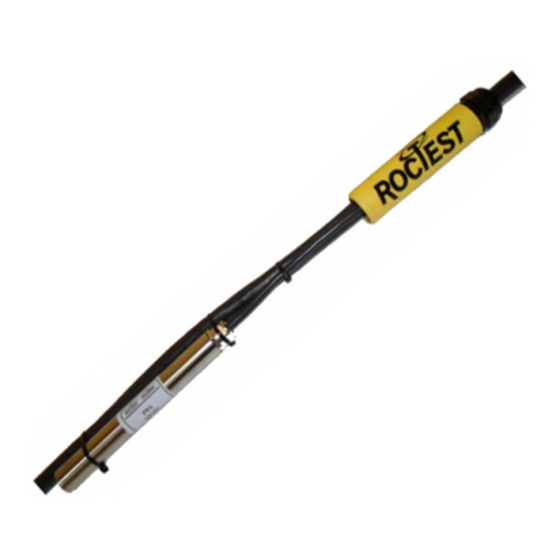
VIBRATING WIRE PIEZOMETER
Model PW
Roctest Limited, 2012. All rights reserved.
This product should be installed and operated only by qualified personnel. Its misuse is potentially dangerous. The Company makes no warranty as to the information furnished
in this manual and assumes no liability for damages resulting from the installation or use of this product. The information herein is subject to change without notification.
Tel.: 1.450.465.1113 • 1.877.ROCTEST (Canada, USA) • 33.1.64.06.40.80 (France) • 41.91.610.1800 (Switzerland)
www.roctest-group.com
E1100D-120118
Advertisement
Table of Contents

Related Manuals for ROCTEST PW Series


Summary of Contents for ROCTEST PW Series
- Page 1 The information herein is subject to change without notification. Tel.: 1.450.465.1113 • 1.877.ROCTEST (Canada, USA) • 33.1.64.06.40.80 (France) • 41.91.610.1800 (Switzerland) www.roctest-group.com...
-
Page 2: Table Of Contents
TABLE OF CONTENTS 1 APPLICATIONS ......................1 2 PRODUCT ......................... 1 2.1 General description ..................... 1 2.2 Description details and specific uses ..............1 2.2.1 Model PWS and PWC ................. 1 2.2.2 Model PWF ....................2 2.2.3 Model PWP ....................2 2.2.4 ... - Page 3 4.2 Taking measurements ..................19 4.3 Quick verification of measurements ..............20 5 CONVERSION OF READINGS ................20 5.1 Pressure value ....................20 5.2 Temperature value .................... 22 5.3 Temperature and barometric corrections ............22 6 TROUBLESHOOTING .................... 23 6.1 Unstable reading ....................
-
Page 4: Applications
E1100D-120119 1 APPLICATIONS The PW series vibrating wire piezometer is designed to measure pore water or other fluid pressures. It is used to monitor engineering works such as hydraulic structures (dams, embankments, land fill dikes…), foundations, retaining walls, excavations, tunnels, etc. -
Page 5: Model Pwf
E1100D-120119 A filter can be set in the front end of the housing and sealed with an o-ring. With the filter in place, the diaphragm is protected from solid particles, and senses only the fluid pressure to be measured. The filter housing is easily removable for calibration and saturation. -
Page 6: Model Pwl
E1100D-120119 2.2.4 MODEL PWL The PWL piezometer model is a low pressure sensor. Similar to the PWS model, a pipe-threaded adapter or a filter can be set in the front end of its housing. 2.2.5 MULTI-LEVEL PIEZOMETER The multi-level piezometer provides significant advantages in terms of time, resources and cost reduction related to installation, while providing quick and reliable reading at various depths. -
Page 7: Operation Principle
E1100D-120119 Stainless steel filter Ceramic filter low air pressure entry high air pressure entry pore diameter: ~50 µm pore diameter: ~1 µm Filter usually installed for use in Filter generally used. unsaturated fine grain material. Does not allow suction measurements. Allow measuring suction to -100 kPa. -
Page 8: Calibration
A portable unit as the MB-3TL (or MB-6T(L)) can be used to read vibrating wire sensors. It proceeds to all necessary operations: wire excitation, signal conditioning and reading display. Contact Roctest – Telemac for further information. 2.4 CALIBRATION A calibration data sheet is supplied with each sensor. It enables conversion of gross readings into pressure values and temperature correction. -
Page 9: Filter Installation
E1100D-120119 For details about how to take readings or how to convert frequency into linear units, please refer to chapter 4 page 19 (Reading Procedure). 3.2 FILTER INSTALLATION 3.2.1 LOW AIR ENTRY SINTERED STAINLESS STEEL FILTER The filter is shipped already mounted on the piezometer body. It should be removed by holding the piezometer in one hand, pulling, and twisting the filter housing with the other hand. -
Page 10: Initial Reading
E1100D-120119 reading). 3.3 INITIAL READING Before installing the piezometer in its final location on site, an initial reading has to be taken to correctly convert readings in linear units into pressure measurements when the piezometer is in operation. This process is also necessary to be able to apply later temperature and barometric corrections. -
Page 11: On Site Calibration Check (Optional)
E1100D-120119 Figure 3: Summary of the different readings Note: It is not necessary at this step to apply corrections to pressure calculation, but it is important to record both temperature and barometric pressure. 3.4 ON SITE CALIBRATION CHECK (OPTIONAL) Piezometers are calibrated in factory with high precision calibrators having an accuracy at least four times better than the accuracy of the piezometer. -
Page 12: Sensor Installation
E1100D-120119 the pipe. Barometric pressure should be recorded along with the readings. Note that when installing a piezometer into a standpipe, the water level raises due to the volume inserted (piezometer body and cable). This has an effect especially with small diameter pipes and long cable lengths. -
Page 13: Installation In Borehole
E1100D-120119 Before backfilling, the cable must be laid with the utmost care. Loop the cable around the recess; make sure it is resting on a bed of hand placed and compacted screened clay. Make sure that the cable does not cross over itself or other cables in the same area. Keep the cables apart. - Page 14 E1100D-120119 backfill materials from sticking to and plugging the casing. 2. Raise the casing fifteen centimetres and pour sand bellow its bottom. Repeat the operation once and lower the piezometer to the top of the sand. Check the borehole depth after each operation. 3.
-
Page 15: Piezometers Driven In Soft Ground
E1100D-120119 Figure 4: Typical installation of piezometers in a borehole Note that an alternate way to install piezometers in boreholes is to fill the entire borehole with grout after having lowered the instruments. Although this method is promising, there is presently a lack of feedback from real situations which makes difficult to know its benefits and its drawbacks. -
Page 16: Installation Of A Multi-Level Piezometer
E1100D-120119 The piezometer cable is threaded through the rods leaving around fifty centimetre loop of cable laying flat on the ground each time the cable emerges from one rod and enters a subsequent rod. Let about seven meters of free cable extends beyond the lower extremity of the first rod. -
Page 17: Datum Reading
E1100D-120119 3.6 DATUM READING Due to the operations during the installation of the instruments, the pore water pressure may take time to come back to its natural state. This can take a few hours to a few weeks, depending of the soil permeability. After installation, take readings periodically to determine a correct datum reading. -
Page 18: Horizontal Cable Runs
E1100D-120119 hand placed concrete is sometimes used, depending on site conditions. During the cable routing, read the instruments at regular intervals to ensure continued proper functioning. Check that the cable does not cross over itself or other cables in the same area. Record the cable routing with care and transfer this routing to the drawings. -
Page 19: Vertical Cable Runs
E1100D-120119 Figure 6: General view of horizontal cable routing 3.7.4 VERTICAL CABLE RUNS The procedure shown below is an efficient and safe way to route cables from the sensor to the top of the embankment or of the dam. Figure 7: Procedure to route vertically cables (continued) Page 16... -
Page 20: Splices
E1100D-120119 Figure 7: Procedure to route vertically cables 3.8 SPLICES Generally, cable splices are to be avoided. If necessary, use only the manufacturer’s approved standard or high-pressure splice kit. Splicing instructions are included with the splice kit. Should the cable be cut, we recommend the use of our high pressure cable splice kits, especially if the splice is located underwater. -
Page 21: Cable Wiring
Actually, individual sensor cables can be merged into a multi-conductor cable using a splice or junction box. Figure 8: Example of junction box use Please contact Roctest – Telemac for additional information about junction boxes and splice kits. 3.9 CABLE WIRING Before cutting a cable, make sure of its identification. -
Page 22: Reading Procedure
Please contact Roctest – Telemac for additional information on protecting instruments, junction boxes and data logging systems against power surges, transients and electromagnetic pulses. All junction boxes and data logging systems furnished by Roctest – Telemac are available with lightning protection. 4 READING PROCEDURE 4.1 GENERALITIES... -
Page 23: Quick Verification Of Measurements
E1100D-120119 Flick the power switch towards the “ON” position. The display will successively show: the readout self-testing sequence the gage and thermistor settings the gage NORMAL (N) and LINEAR (L) readings and the temperature of the gage in degrees Celsius and Fahrenheit. Record these numbers as they appear on the display. - Page 24 E1100D-120119 Polynomial equation: where = pressure in kilopascal = current reading in linear units (LU) = calibration factors (see calibration sheet) = calculated constant in kilopascal Examples: The calibration sheet gives the following values: = -3.8444E-01 kPa/LU = -4.0179E-06 kPa/LU = -3.6641E-01 kPa/LU...
-
Page 25: Temperature Value
E1100D-120119 If the frequency is measured, convert it into linear units using the following equation: L 1000 where = reading in linear units = gage constant for piezometer = 1.0156 = frequency in Hz Example: With = 1 625 Hz, 1625 ... -
Page 26: Troubleshooting
E1100D-120119 Use the following relation to apply corrections: where = corrected pressure in kilopascal = pressure previously calculated in kilopascal = thermal coefficient (see calibration sheet), in kPa/°C = current temperature reading in degrees Celsius = initial temperature reading in degrees Celsius = current barometric pressure reading in kilopascal = initial barometric pressure reading in kilopascal... -
Page 27: No Reading
- Cuts or shorts are located, the cable may be spliced in accordance with procedures recommended by Roctest – Telemac. - The sensor may have been damaged by shocks or water may have penetrated inside its body. -
Page 28: Other Troubles
E1100D-120119 sensor body. There is no remedial action. 6.4 OTHER TROUBLES If pressure variations are suspicious, check if those variations are correlated to recorded temperature and/or barometric pressure. Check if corrections to raw pressure are applied correctly. 7 MISCELLANEOUS 7.1 ENVIRONMENTAL FACTORS Since the purpose of piezometer installation is to monitor site conditions, factors which may affect these conditions should always be observed and recorded. -
Page 29: Conversion Factors
E1100D-120119 7.2 CONVERSION FACTORS To Convert From Multiply By Microns Inches 3.94E-05 LENGTH Millimetres Inches 0.0394 Meters Feet 3.2808 Square millimetres Square inches 0.0016 AREA Square meters Square feet 10.7643 Cubic centimetres Cubic inches 0.06101 Cubic meters Cubic feet 35.3357 VOLUME Litres U.S. - Page 30 E1100D-120119 APPENDIX 1 EXAMPLE OF CALIBRATION SHEET Page 27...
Need help?
Do you have a question about the PW Series and is the answer not in the manual?
Questions and answers