Table of Contents
Advertisement
Quick Links
INSTRUCTION MANUAL
BOREHOLE DILATOMETER
(ROCK PRESSUREMETER)
Model PROBEX
Roctest Limited, 2015, 2017, 2018. All rights reserved.
This product should be installed and operated only by qualified personnel. Its misuse is potentially dangerous. The Company makes no warranty as to the
information furnished in this manual and assumes no liability for damages resulting from the installation or use of this product. The information herein is
subject to change without notification.
Tel. : 1.450.465.1113 • 1.877.ROCTEST (Canada, USA) • 33 (1) 64.06.40.80 (Europe) • www.roctest.com • www.telemac.com
E10037-180424
Advertisement
Table of Contents

Related Manuals for ROCTEST PROBEX


Summary of Contents for ROCTEST PROBEX
- Page 1 The information herein is subject to change without notification. Tel. : 1.450.465.1113 • 1.877.ROCTEST (Canada, USA) • 33 (1) 64.06.40.80 (Europe) • www.roctest.com • www.telemac.com E10037-180424...
-
Page 2: Table Of Contents
CONNECTING AND TURNING ON DP BOX ..........8 2.2.3 USING THE DP BOX READER APPS ............9 2.2.4 SATURATION OF THE PROBEX ............15 CALIBRATION OF THE PROBEX ............16 PRESSURE LOSS CALIBRATION ............16 2.4.1 VOLUME LOSS CALIBRATION ............. 16 2.4.2... -
Page 3: Equipment
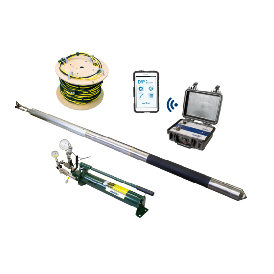
A manually-operated, hydraulic pump together with hydraulic tubing and a readout unit complete the PROBEX system. The PROBEX probe is mounted on a steel core C, which is fitted with a saturation plug at its downstream extremity. Water saturation of the system fills the annular space between the dilatable membrane and the steel core as well as cylinder E. - Page 4 E10037-180424 PROBEX Potentiometer Schematic Representation of the PROBEX...
-
Page 5: Probe
73.7 mm. This configuration gives an L/D ratio for the dilatable portion of the probe greater than 6. It cannot be overly emphasized that PROBEX tests should be run in well calibrated, N-size boreholes having diameters of 76 mm. Performance of the PROBEX will then be enhanced and the risk of damaging a probe greatly reduced. -
Page 6: Readout Unit
E10037-180424 PROBEX rating of the pump is 69 MPa. A cyclic test valve is located on the inflation circuit between the gauge block and the pump (this valve must always be kept open except when doing cyclic load tests). Two pressure dial gauges are mounted on the hydraulic pump. The gauge controlling testing pressure is installed on the inflation circuit (position No. -
Page 7: Operating Instructions
Never pull on the cable Note 4 : WARNING: The operator must ensure that all 4 hydraulic connections to the pump and to the PROBEX probe are properly made to avoid potential damage to the hydraulic system. - Page 8 E10037-180424 PROBEX Thread this end of tubing & cable through sufficient number of casing lengths to reach maximum testing depth PROBEX Assembly...
-
Page 9: Using The Dp Box
The DP BOX is designed for reading and logging measurements obtained from pressuremeters and dilatometers manufactured by Roctest (including models DMP 95, TEXAM and PROBEX). Thanks to the Bluetooth communication feature and to the DP Box READER Application, the DP Box can be used in conjunction with a Tablet for reading the sensors, for configuring a calibration or a testing session, for visualizing and logging the test results in real time, and for reviewing any test data. -
Page 10: Installing The Dp Box Reader Apps
2.2.2 INSTALLING THE DP BOX READER APPS Prior from using the DP Box, the DP Box READER Application should be installed on a Tablet. This application can be downloaded from Roctest web site. 2.2.3 CONNECTING AND TURNING ON DP BOX Connect the electrical cable of the testing equipment to the DP Box. -
Page 11: Using The Dp Box Reader Apps
E10037-180424 PROBEX Make sure the battery voltage of the tablet is high enough for use. Open the DP Box Application and go in ‘Settings / Quick Reading’ for establishing Bluetooth communication between the DP Box and the Tablet, which will be confirmed when the DP box LED will blink quicker (see below for more information). - Page 12 DP Box Application Main Menu 2.2.4.2 USING THE DP BOX READER APPS WITH THE PROBEX First, Go to ‘Settings’. The APPS will automatically scan for establishing Bluetooth communication with the DP BOX, which takes a few seconds. The name of the DP Box...
- Page 13 PROBEX The DP Box name should appear here Go to ‘Instrument / Add a New Instrument’ and Select the ‘Type of instrument’ (PROBEX) and enter the serial number appearing on the control unit (e.g. 003717003). Select for additional functions (Editing,...
- Page 14 E10037-180424 PROBEX Make sure the conversion factors associated to this instrument have been entered. Refer to the calibration certificate. For changing these, select ‘Calibration / Cal. Type / Review Factory Calibration’ and select ‘Change factory calibration’, make the appropriate changes and select ‘Save new factory calibration’...
- Page 15 E10037-180424 PROBEX For configuring a test, go to ‘Test’ and proceed the same way. Typical set up: Timer Typical (sec) ‘CAP+Date’ Pressure loss calibration ‘CAV+Date’ Volume loss calibration ‘TE+Date’ Test The Apps will automatically increment selected ID Once setup is completed, select: ‘Begin Calibration or Test’ to start.
- Page 16 E10037-180424 PROBEX Battery level of the Tablet and of the DP BOX For starting the timer. Readings are Displays actual Pressure automatically recorded and Volume readings each time timer gets to zero Graph is plotted here For stopping the calibration/test When the calibration or test is over, press on : For reviewing results, go to ‘Data Files’, the select ‘Calibration’...
-
Page 17: Saturation Of The Probex
STEP 2. The conical end cap A is removed from the probe. STEP 3. The PROBEX is inclined at least 20 degrees the saturation plug being at its uppermost point. The probe is then turned until the small notch at the end of the steel core C is in the upper position. -
Page 18: Calibration Of The Probex
The volume correction factor ‘c’ is given by the following equation c = a – b. Where ‘a’ is the PROBEX volumetric expansion obtained from the Volume Calibration, and ‘b’ corresponds to the (small) theoretical expansion of the calibration tube when... -
Page 19: Borehole
E10037-180424 PROBEX For a representative ‘c’, the user must conduct numerous volume NOTE: calibrations prior to testing and in the same environmental conditions. When delay between calibrations and testing exceeds two hours, kneading of the membrane should be repeated. Therefore, we suggest beginning each testing day by doing these calibrations, which takes more than an hour. -
Page 20: Setting The Probe In Place
Check the battery charge. STEP 5. Insert the PROBEX into the borehole. To avoid the risk of damaging or losing the probe in unstable boreholes, the electrical cable and tubing are normally threaded in a NQ rods (or BW casing) before inserting the probe in the borehole. - Page 21 E10037-180424 PROBEX Slotted adapter NQ to AW Rods or BW Casing to NQ Rods Methods Used for Lowering Probe in Place...
-
Page 22: Testing Procedure
2. The dual-action piston will be fully retracted when the readout shows a zero reading. STEP 7. Withdraw the PROBEX from the hole or move it to the next testing position. Note that tests are normally carried out from lowest testing elevation upward. Standard spacing between tests is 1.5 m. -
Page 23: Data Reduction
PROBEX DATA REDUCTION Test results from the PROBEX are essentially used for measuring in situ deformability of rock mass. The method for doing so is the same one used to reduce pressuremeter data. It is based on Lame’s equations and it yields a mean modulus of deformation for the rock mass tested. - Page 24 (modulus of elasticity): 207 x 10 m (Poisson's ratio): 0.30 Using these values in the previous equation and assuming a dilatable length of the PROBEX membrane equal to 457 mm, one obtains the following "b" value: b = 86.6 x 10...
-
Page 25: Miscellaneous
However, it is not recommended to follow this unload-reload sequence with the PROBEX in hard rock. The use of the PROBEX is possible in hard rock, but special precautions are necessary. -
Page 26: Membrane Burst
Stop the test earlier in case of unusual rock response. The following chart can be followed: PROBEX - Maximum Pressure - Volume Values Unless otherwise specified, the test is terminated typically when reaching 30 MPa in sound rock, when sufficient data has been accumulated for the intended purposed of the test, or before reaching high risks of bursting the probe as indicated on this chart. -
Page 27: Replacement Of The Membrane
PROBEX REPLACEMENT OF THE MEMBRANE For clarification purposes, the user should note that when the PROBEX probe is taken off the steel core of the probe, he has in his hands a unit composed of elements No. 8, 9, 10, 11 and 14 shown on Figure below. -
Page 28: Maintenance
NEVER ROTATE THE BRASS PIECE !. Membrane Diameter With use, the PROBEX membrane will deform in a plastic way resulting in a diameter increase. This phenomenon will not invalidate test results, but may prevent PROBEX insertion in the calibration tube or in the borehole. For preventing that: the membrane should be periodically sandblasted by hand. -
Page 29: Cold / Hot Temperature
(6) Labrie D., Conlon B., Anderson T. and Boyle R.F. 2004, Measurement of insitu deformability in hard rock, Proceedings of 57 Canadian Geotechnical Conference, 9-16. (7) Marcil L., Green R. and Baures T. and Boyle R.F. 2013, The PROBEX: Over 25 Years of Experience in Measuring Deformability of Rock, ISP6...
Need help?
Do you have a question about the PROBEX and is the answer not in the manual?
Questions and answers