Table of Contents
Advertisement
Quick Links
Advertisement
Table of Contents

Related Manuals for DORIC Connectorized LED Series

Summary of Contents for DORIC Connectorized LED Series
- Page 1 Connectorized LEDs & LED Drivers User Manual Version 1.1.2...
-
Page 2: Table Of Contents
..........3.3 Stand-alone mode (without Doric Neuroscience Studio Software) . -
Page 3: Safety Information
Doric LED Drivers are provided with a safety interlock connector on its rear panel (Fig. 1.1a). When the interlock circuit connector is shorted with the interlock plug, the driver is enabled. The shorting electric wire in the interlock plug can be removed and replaced by the safety interlock circuit of the laboratory. -
Page 4: Overview
Figure 2.1: Connectorized LED The Doric Connectorized LED is a compact module that couples a high brightness LED into an optical fiber via an FC receptacle. It is available in wavelengths from 365 nm to 940 nm, as well as white (5500 K temperature). The module connects to the Doric LED Driver over the pigtailed M8 electrical cable. -
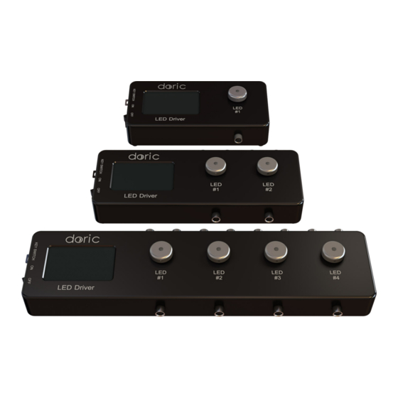
Page 5: Led Drivers
Figure 2.2: LED Drivers; 1-, 2- and 4-channel Doric LED Drivers can be used as a stand-alone device or controlled via USB port. Each channel connects to a single Connectorized LED which can be controlled manually or via the Doric Neuroscience Studio Software. - Page 6 • The Power key must be properly inserted into the key switch to enable operation of the light source(s) connected to the driver. Note that, despite its similar shape, the power key is not a standard micro SD card such as those used in some digital cameras.
-
Page 7: Led Breadboard
2.3 LED Breadboard The LED Breadboard is a small breadboard used to hold two Connectorized LEDs; this allows the light sources to be easily moved when necessary. It is ordered separately from the light source. Figure 2.6: LED Breadboard with LEDs Installed Chapter 2. -
Page 8: Operations Guide
Operations Guide 3.1 Connectorized LED Setup Figure 3.1: Connections to a 1-channel LED Driver in stand-alone mode 1. Connect the LED Driver to the 12 VDC power supply. -
Page 9: Fc Connector Installation
• DO NOT connect/disconnect the optical fiber while the light source is ON. • The CLED can be operated with the driver’s stand-alone capabilities (Section 3.3) or using the Doric Neuro- science Studio software (Section 3.4). 3.2 FC Connector Installation 1. -
Page 10: Stand-Alone Mode (Without Doric Neuroscience Studio Software)
3.3 Stand-alone mode (without Doric Neuroscience Studio Software) The following sections details stand-alone operation of the LED driver. For installation of the LEDC in stand-alone mode, see section 3.1. 3.3.1 Driver operation modes with the stand-alone device If the light source driver is used as a stand-alone device, 3 modes are available: constant current (CW), external TTL (Ext. - Page 11 External Analog (Ext. Ana.) Figure 3.5: External analog pulse sequence behavior The External Analog mode is similar to the External TTL, except that the driving current is proportional to the voltage ap- plied on the BNC input connector (Fig. 3.5, top). On the input BNC, a maximum voltage signal corresponds to a maximum driver current.
-
Page 12: Connected To Doric Neuroscience Studio Software
2. Install the Doric Neuroscience Studio Software on the computer. Double-click on the setup DoricStudioX.X.exe file located on Doric USB memory stick supplied with the LED driver and follow the on-screen instructions. 3. Connect the USB cable to the driver and the computer. -
Page 13: Doric Neuroscience Studio
4.1 Light Sources Doric Light Sources can be controlled by the Doric Neuroscience Studio. These include LED Modules, Laser Diode Modules and Ce:YAG Fiber Light Source. The interface is separated into two main sections, Control & settings and the Acquisition View. - Page 14 Doric Neuroscience Studio. These function are used through the Channel Config- uration window (Fig. 4.2). Figure 4.2: Light Source Channel Configuration Window 1. The Channel Types (Fig. 4.2) are displayed on the left side of the window. These include Laser light sources, Ce:YAG light sources and LED light sources, as well as the Scope to measure signal using the driver.
- Page 15 See the corresponding light source manual to find the voltage/current rela- tionship. This mode has no additional sequence options. Chapter 4. Doric Neuroscience Studio...
- Page 16 ON must be lower than (1/frequency)+0.005 ms, while the Duty cycle must be below 100 %. These squares will appear red should an impossible Frequency/time ON be selected. Should the Smoothing option be selected, this feature becomes inaccessible. Chapter 4. Doric Neuroscience Studio...
- Page 17 The Total Duration (Fig. 4.6) displays the total time of the experiment. The different values can be Inf for infinite, a valid time value or Err if the Time ON value is greater than 1/frequency. Figure 4.8: Complex Sequences Window Chapter 4. Doric Neuroscience Studio...
- Page 18 4. The Preview box (Fig. 4.2) displays a preview of the chosen sequence while in the Continuous Wave, Square Sequences and Complex Sequences mode. 5. The Apply button (Fig. 4.2) will generate the defined channel OR update an already configured channel with any changes. Chapter 4. Doric Neuroscience Studio...
- Page 19 3. The Save configuration button saves all currently configured channels in .doric format. 4. The Load configuration button loads a file in .doric format that contains a previously saved set of configured channels. 5. The Start All button (Fig. 4.11) starts all currently configured channels.
- Page 20 The Current Slider allows the light source current to be adjusted. e) The Status box displays the status of the channel (Light source or Scope). The Status will display RUN- NING... when active and STOPPED when deactivated. Chapter 4. Doric Neuroscience Studio...
- Page 21 The Export scope channel button allows the recording of a live measurement sequence on the scope. 4. The Graph View displays either a preview of the pulse sequence for Light Source Channels or the received signal for the Scope Channel. Chapter 4. Doric Neuroscience Studio...
-
Page 22: Specifications
Specifications Table 5.1: Typical Connectorized LED Output Power vs Optical Fiber Core Diameter Overdrive TYPICAL OUTPUT POWER @2000 mA @1000 mA (mW) (pulsed) Central Bandwidth Core 200 µm Core 400 µm Core 960 µm Wavelength (nm) FWHM (nm) 0.53 NA 0.53 NA 0.63 NA x1.7... - Page 23 Table 5.2: General specifications for LED Drivers SPECIFICATION VALUE NOTE Power supply 110 - 240 VAC; 50 - 60 Hz Power supply adapter included DC power supply 12 VDC 20 W (1-ch, 2-ch), 60 W (4-ch) Mass 1-channel model 580 g (1.28 lbs) 2-channel model 757 g (1.67 lbs) 4-channel model...
- Page 24 Table 5.4: Recommended Environmental specifications SPECIFICATION OPERATION STORAGE Indoor Indoor Temperature 20 C to 30 C -20 C to +60 C Humidity 40-60 % RH, non condensing 40-60 % RH, non condensing Chapter 5. Specifications...
-
Page 25: Annex 1: Safety Features
Annex 1: Safety features 6.1 Activation Safety Features The drivers for all Doric Lenses light sources come with a number of safety features. These are built into the driver circuits, as shown in the block diagram (Fig. 6.1). Figure 6.1: Safety feature block diagram •... -
Page 26: Emission Indicator
– The Interlock Plug comes with a small wire short-circuiting it. This wire must be removed before integrating it into an Interlock Circuit. – Connect the Interlock circuit in series with the Interlock Plug so the circuit may function properly. •... -
Page 27: Support
7.2 Warranty This product is under warranty for a period of 12 months. Contact Doric Lenses for return instructions. This warranty will not be applicable if the unit is damaged or needs to be repaired as a result of improper use or operation outside the conditions stated in this manual.
Need help?
Do you have a question about the Connectorized LED Series and is the answer not in the manual?
Questions and answers