
Related Manuals for WOBIT MIC488


Summary of Contents for WOBIT MIC488
- Page 1 MIC488 USER MANUAL Programmable motion trajectory controller for 4 axis P.P.H. WObit E.K.J. Ober s.c. 62-045 Pniewy, Dęborzyce 16 tel. 61 22 27 422, fax. 61 22 27 439 e-mail: wobit@wobit.com.pl www.wobit.com.pl...
- Page 2 This information does not release the user from the obligation of own judgment and verification. P.P.H. WObit E.K.J. Ober s.c. reserves the right to make changes without prior notice.
-
Page 3: Table Of Contents
Universal outputs OUT1…OUT8 ............................... 9 Outputs for M1…M4 ..................................10 Connection example ..................................10 Software MIC488-PC .................................. 11 Connection MIC488 with PC via USB .............................. 11 Program description ..................................12 Driver configuration ................................... 13 Initial information – motion parameters ............................13 Drives configuration .................................. -
Page 4: Safety And Assembly Rules
(separate kink for A and B phase). It is recommended to use a ferrite bead assumed on the motor wire in close to the driver. Please avoid leading signal cables (CLK, DIR, EN) parallel or in close to electrical and power wire of the motor; signal cables should be possibly short. www.wobit.com.pl User manual MIC488 –16.07.2015r. v.1.25 page 4... -
Page 5: Device Description
2. Device description Designation MIC488 is a programmable 4-axle driver. Its main function is to control 4 stepper or servo motors in CLK/DIR mode. The controller allows to connect incremental encoder for master position control. Except of universal I/O and two 0-10 V inputs the driver is equipped with RS232, RS485 interfaces operating in MODBUS (slave) protocol which enables connection with e.g. -
Page 6: Functions
Intuitive software for driver configuration and programming Functions Main function of MIC488 driver is control of 4 drives in CLK/DIR mode. The controller is generating motion trajectory which includes ramp (acceleration, constant velocity, braking) to achieve smooth motion without lose of position. -
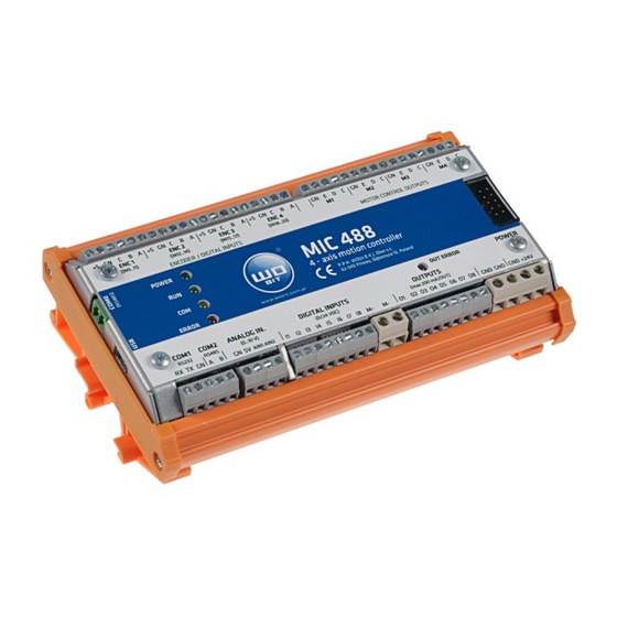
Page 7: Equipment Description
3. Equipment description Connectors and indicating lamps layout Picture. 1 Description of connectors and indicating lamps MIC488 driver. Name Description Data receiving Transmitting RS232 Interface Ground Signal + RS485 Interface Signal - Ground Output +5V (max. 100mA) Analog inputs 8, 9 A1,A2 Analog inputs 0…10V... -
Page 8: Power Supply
Inputs have no insulation, common signal (negative) is ground of driver power supply GND (GN). Additionally next to inputs are located voltage outputs +5 V which can be used for direct supply of encoders TTL 5 V type. www.wobit.com.pl User manual MIC488 –16.07.2015r. v.1.25 page 8... -
Page 9: Universal Outputs Out1
Universal outputs OUT1…OUT8 allows control of external executive elements which current consumption not exceed 200 mA. Outputs in active state give driver voltage supply VDC+. Common signal for outputs is driver supply ground GND (28, 29, 30, 31 clamps). www.wobit.com.pl User manual MIC488 –16.07.2015r. v.1.25 page 9... -
Page 10: Outputs For M1
Picture. 9 Outputs M1..M4 for drives control Connection example On picture below is presented signals connection example to MIC488. The driver is controlling one M1 drive. Hash mark indicates optional connection of incremental encoder for additional position control (for M1 drive encoder should be connected to ENC1 encoder channel). -
Page 11: Software Mic488-Pc
The driver should be connected with PC by USB cable type A – B mini. After connecting with the computer it is permitted to turn on the supply of the driver and to run MIC488-PC software. Correct communication will be signalized by information in program upper window. -
Page 12: Program Description
Signals from RS485 converter (A, B) should be connected to A and B signals of COM0 port of the driver. To establish connection at MIC488-PC program please select on toolbar Connection -> Settings. At open window select COM0 connection. If number COM port on PC side is known please select this port and set baudrate (57600) then press button Connect. -
Page 13: Driver Configuration
Add-ons – I/O preview [this function is also available at button (3) ], Preview of X/Y [this function is also available at button (3)], JOG control (this function is also available at „Manual control”), Options – general settings of MIC488-PC application. Info – information about MIC488-PC program. -
Page 14: Drives Configuration
Setting of new velocity during motion will cause reaching new velocity in view of AccMX ramp. Drives configuration Configuration of drives is made at tab Configuration-> Drives. www.wobit.com.pl User manual MIC488 –16.07.2015r. v.1.25 page 14... - Page 15 It defines reinforcement of position regulator for position control from encoder mode. The bigger value the faster position setting after lost of step. Default 50. - setting required in case of operation with encoder for drive position control. www.wobit.com.pl User manual MIC488 –16.07.2015r. v.1.25 page 15...
-
Page 16: Homing And Motion Limiting Mode
(back in front of sensor). HOME2: Precise homing mode 2. Drive is reaching proximity sensor (mounted in end position), stops and then slowly forward move until signal decline from sensor (drive across sensor). www.wobit.com.pl User manual MIC488 –16.07.2015r. v.1.25 page 16... -
Page 17: Position Control With Encoder
By default this registers store maximal range values of positions. 5.2.2. Position control with encoder MIC488 can control motor position based on external encoder connected to ENC inputs (ENC1…4 for next drives M1…M4). Way of encoder connection is presented at Błąd! Nie można odnaleźć źródła odwołania. chapter. - Page 18 Configuration (without encoder) Motor driver is connected to M1 output of MIC488. Sensor KL signal is connected to IN1 input and KR signal to IN2 input. In M1 drive settings (tab Konfiguracja -> Napędy -> M1) (tab Configuration ->Drives -> M1) enter...
-
Page 19: Control Of Drive Status
KR) 5.3. Digital inputs configuration Configuration consider only IN1…IN8 inputs used in program as universal inputs. Settings has no influence on inputs operation in drive position/homing function. www.wobit.com.pl User manual MIC488 –16.07.2015r. v.1.25 page 19... -
Page 20: Analog Inputs Configuration
For example for input voltage 0V AIN value is -25 and for 10V +25. Then should be entered: AIN_LOVAL: -25 AIN_HIVAL: +25 5.5. RS232/RS485 communication configuration Picture. 22 Setting of RS232/RS485 communication. www.wobit.com.pl User manual MIC488 –16.07.2015r. v.1.25 page 20... -
Page 21: Manual Control And Diagnostics
Parity: none COM1 (RS232) and COM2(RS485) ports enables communication with devices using MODBUS-RTU protocol. MIC488 is a SLAVE device. In device settings is possible to change transmission baudrate for each port independently. Setting of SLAVE address of the device should be made for COM1 port. It is common for COM2 port. Change of address for COM2 port doesn’t matter. -
Page 22: Diagnostics
By buttons located above IN1..IN8 inputs and OUT1..OUT8 outputs is possible to simulate its operation. Inputs simulation operates also at homing and end sensors function. 6.3 Errors signalization Depend on diodes status MIC488 can signalize following errors: Diode status Type of error... -
Page 23: Driver Programming
„PABS M1 10” (motion into absolute position 10 of M1 drive) or „SET OUT3 = ON” (turning on O3 output). This language thanks to simple text commands allows in easy and fast way create programs for MIC488 driver. From level of created program is possible freely control of drives motion, control of universal outputs, reaction on inputs, counting pulses from encoder, time delay functions, simple mathematic operations, operations on variable available through MODBUS etc. -
Page 24: Wbcprog Program Description
Furthermore it is possible to run selected program and position table by proper MODBUS registers. 7.2. WBCprog program description 7.2.1 Main window Picture. 26 Main window of WBCprog program. 1) Toolbar: Contains access to all program functions. 2) Shortcut bar: www.wobit.com.pl User manual MIC488 –16.07.2015r. v.1.25 page 24... -
Page 25: Saving And Opening A Project
Saving a project will cause an automatic creation of this files. 7.2.3 Quick commands menu Right-click into selected line at editor window (5) cause appearing menu which allows adding selected commands. Picture. 29 Quick commands menu. www.wobit.com.pl User manual MIC488 –16.07.2015r. v.1.25 page 25... -
Page 26: Position Table
It will open a window where user defines data to be send: PROGRAM – if we want send a program POSITIONS – if we want to send position tables www.wobit.com.pl User manual MIC488 –16.07.2015r. v.1.25 page 26... -
Page 27: Running And Testing Of The Program
Hints panel please right-click on selected register (at Registers tab) or on variable (at Variable tab) and press „Add to preview”. Picture. 5 Way of adding registers / variables to preview. www.wobit.com.pl User manual MIC488 –16.07.2015r. v.1.25 page 27... -
Page 28: Wbl Language Description
Picture. 6 Delete from preview. 7.3. WBL language description WBL language (WObit Basic Language) is a simple text language similar to BASIC or ST (Structured Text) designed for creating motion programs for MIC488 driver. It facilitates creating programs for drives motion execution and is more flexible comparing to other languages. - Page 29 Values saved/readied out by MODBUS can be INT, DINT, REAL type. To correctly interpret different data types before register address pleas use prefix: $I – for values INT type $D – for values DINT type www.wobit.com.pl User manual MIC488 –16.07.2015r. v.1.25 page 29...
-
Page 30: Program Example In Wbcprog
0 (OFF) – interrupt turned off 4 (HIGH) – interrupt turned on Program example in WBCprog Below are placed examples using individual functions of MIC488 driver. Additionally in program catalogue named WBC examples are placed ready examples. 8.1 Use of inputs / outputs Used registers: ... -
Page 31: Read Out Of Analog Inputs (0-10V)
Activation of M1 drive M2_EN Activation of M2 drive Stopping/braking drive in motion STOP Stop of M1 drive (rapid) BRAKE Braking of M2 drive (braking to 0 velocity) Homing of a drive www.wobit.com.pl User manual MIC488 –16.07.2015r. v.1.25 page 31... -
Page 32: Linear Interpolation
8.3.1 Linear interpolation MIC488 allows to execute linear interpolation using M1 and M2 drives which create X and Y axes. Interpolation adjust velocity of both drives to finish its motion at the same moment. Caution – please set the same parameters for ramp for both drives. -
Page 33: Circular Interpolation
// Waiting for end of motion 8.3.2 Circular interpolation MIC488 allows to execution of circular interpolation using M1 drives M2 which create X and Y axes. To provide correct operation of interpolation function, GEAR parameter at M1 and M2 drives configuration should be the same (to correctly execute a circle drives must have the same mechanical ratio). -
Page 34: Readout / Save Of Encoder Position
// Waiting for execution a circle 8.4. Readout / Save of encoder position Used registers: ENCX – value of encoder counter in pulses XENCX – value of encoder counter converted into drive rotations www.wobit.com.pl User manual MIC488 –16.07.2015r. v.1.25 page 34... -
Page 35: Timers
JUMP MAIN // Interrupt label at IN1 input – there will occur a jump when at INT_IN1: // IN1 input will occur a high state // Do sth... // return from interrupt REURN www.wobit.com.pl User manual MIC488 –16.07.2015r. v.1.25 page 35... -
Page 36: Program Example
// Stop the drive SET OUT_STOP = // Activate OUT1 output DELAY // Wait 2 sec. SET OUT_STOP = // Turn off OUT1 output ENDIF RETURN // Return to place before jump www.wobit.com.pl User manual MIC488 –16.07.2015r. v.1.25 page 36... -
Page 37: List Of Commands And Registers
Increasing (reducing) of current velocity. Y – relative velocity PABS MX Y PABS Setting of absolute position (equal to entered value). Y – absolute position PREL Increasing (reducing) of current drive position. PREL MX Y www.wobit.com.pl User manual MIC488 –16.07.2015r. v.1.25 page 37... - Page 38 4 (M_POS_OK) – position achieved StatMX Status of drive operation. 5 (M_POS_ERROR) – position error (M_POS_HOMING) – homing 8(M_POS_CORRECTION) – correction of position 9 (M_POS_LIM_L) – achieved L end position 10 (M_POS_LIM_R) – achieved R end www.wobit.com.pl User manual MIC488 –16.07.2015r. v.1.25 page 38...
-
Page 39: Modbus Communication
- MOVEPTP function can take as an argument also number from table (earlier it was only name of position) position table (earlier it was only name of position) 1.04 - improved position control from encoder www.wobit.com.pl User manual MIC488 –16.07.2015r. v.1.25 page 39... -
Page 40: Technical Parameters
CAUTIONS: SETTINGS RESET - optimize drive control function 1.25 - option of programming by COM0 port (RS485) SETTINGS RESET: After update factory settings will be restored. RECOMPILATION: It requires program recompilation at current MIC488-PC software. 12 Technical parameters Description Parameter Power supply 12…26V DC... - Page 41 Picture. 35 Technical drawing www.wobit.com.pl User manual MIC488 –16.07.2015r. v.1.25 page 41...
-
Page 42: Declaration Of Conformity
Declaration of conformity does not cover any modernizations made inconsistently to the instruction manual and/or without approval of the manufacturer. This declaration of conformity is prepared under the sole responsibility of the manufacturer. Place of issue: Dęborzyce Date of issue: 24.11.2014 r. www.wobit.com.pl User manual MIC488 –16.07.2015r. v.1.25 page 42...
Need help?
Do you have a question about the MIC488 and is the answer not in the manual?
Questions and answers