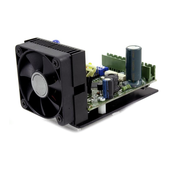
Table of Contents

Summary of Contents for WOBIT SMC64 WP v2
- Page 1 SMC64 WP v2 Manual SMC64 WP v2 – programmable driver for 2-phase bipolar motors P.P.H. WObit E.K.J. Ober s.c. Dęborzyce 16, 62-045 Pniewy tel. 48 61 22 27 422, fax. 48 61 22 27 439 e-mail: wobit@wobit.com.pl www.wobit.com.pl...
-
Page 2: Table Of Contents
Based on the information should not be inferred a certain features or suitability for a particular application. This information does not release the user from the obligation of own judgment and verification. P.P.H. WObit E.K.J. Ober S.C. reserves the right to make changes without prior notice. -
Page 3: Safety And Assembly Rules
2-phase bipolar motors, Thermal, voltage and short –circuit protection (partly, do not protect against short-circuit for power supply an between phases), High rated current 3,5A (4A temp) www.wobit.com.pl Manual -SMC64 WP v2 – 27.10.2014 – v.1.1 page 3... -
Page 4: Power Supply
(A with /A, B with /B). Additionally it is recommended to mount a ferrite bead on a cable. www.wobit.com.pl Manual -SMC64 WP v2 – 27.10.2014 – v.1.1 page 4... -
Page 5: Flowchart
2.3. Flowchart 2.4. Connectors description www.wobit.com.pl Manual -SMC64 WP v2 – 27.10.2014 – v.1.1 page 5... -
Page 6: Driver Configuration
4 /B phase 3 +5 – output +5V 3. Driver configuration 3.1 Selection of step division Step division is made by M1, M2 and M3 jumpers according to scheme below: www.wobit.com.pl Manual -SMC64 WP v2 – 27.10.2014 – v.1.1 page 6... -
Page 7: Selection Of Motor Current
3. 0…5V intput mode (Ain) – at this mode is possible to set frequency for internal generator by changing voltage value on Ain input (J6). Particular operating modes are further described in details. www.wobit.com.pl Manual -SMC64 WP v2 – 27.10.2014 – v.1.1 page 7... -
Page 8: Selected V1/V2 Speed Mode
Therefore turn off a permission signal (EN non active), and on CLK input (1 and 2 clamps of J2 connector) give signal with required frequency, and made all actions from 4 to 6 of procedure above. In this case it is impossible to observe motor work. www.wobit.com.pl Manual -SMC64 WP v2 – 27.10.2014 – v.1.1 page 8... - Page 9 =0 (motor is stopped) Additionally by V1 and V2 jumpers can be calibrated generator frequency. CAUTION! On Ain input can be given voltage from range 0..5V. Do not exceed this range. www.wobit.com.pl Manual -SMC64 WP v2 – 27.10.2014 – v.1.1 page 9...
-
Page 10: Scheme Of Controlling Signals Inputs
1 – signal at low level (+5V) 1 – pin closed 010101- generated signal 1 pins are open during operation of the device 0 1 give signal 1 0 signal decline www.wobit.com.pl Manual -SMC64 WP v2 – 27.10.2014 – v.1.1 page 10... -
Page 11: Technical Data
External power supply connections should be made by ZOAWG cables. Exceeding recommended operating parameters can lead to damage of the device or fire. For cleaning the device do not use cleaning products containing water or oils. www.wobit.com.pl Manual -SMC64 WP v2 – 27.10.2014 – v.1.1 page 11... -
Page 12: Complementary Information
At pictures below are presented current waveforms of windings with applying mentioned modes against distorted waveforms due controlling at typical mode (so called slow), for different velocities and step divisions. www.wobit.com.pl Manual -SMC64 WP v2 – 27.10.2014 – v.1.1 page 12...


Need help?
Do you have a question about the SMC64 WP v2 and is the answer not in the manual?
Questions and answers