Table of Contents
Advertisement
Quick Links
1
1.1
1.2
1.3
2
2.1
2.2
2.3
Recommendations for correct installation for
purposes of EMC
2.4
2.5
2.6
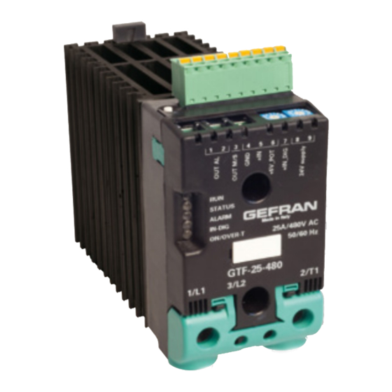
General description GTF 25-120A
2.7
General description GTF 150-250A
2.8
for GTF 150-250A
2.9
Substitution of Internal Fuse
(Option only for GTF 150-250A)
3
Electrical connections
3.1
Power connections
3.2
Connections input/output 25-120A
To differentiate the type and importance of the information in this User Manual, graphic reference symbols are used to make such information
easier to interpret.
indicates contents of sections, general instructions, notes, and
other points to which the reader's attention needs to be called.
Indicates a particularly delicate situation that could affect
the safety or correct operation of the controller, or an
instruction that MUST be followed to prevent hazards.
Indicates a risk to the user's safety due to high voltage at the
points indicated.
80960_MHW_GTF_01-2012_ENG
GTF Plus
advaNcEd Solid STaTE RElayS coMMUNicaTioN WiTH ModBUS
INDEX
2
4
11
GRAPHIC SYMBOLS
INSTALLATION AND
OPERATION MANUAL
code 80960 - 01-2012 - ENG
3.3
Connections input/output GTF 25-120A
3.4
Functions of indicator leds
3.5
Control connectors
3.6
Configuration TTL port (GTF standars)
3.7
Serial comunication port Modbus RS485 (option)
3.8
Connection example: comunication ports
3.9
Connection example: power section
4
Installation of serial network
4.1
"AUTOBAUD SERIAL" sequence
5
Technical Characteristics
5.1
Derating Curves GTF without electronic fuse
(with SCR)
5.2
Derating Curves GTF with electronic fuse
(with IGBT)
6
Technical-Commercial information
6.1
Accessories
6.2
Fuses / Fuseholders
Indicates a suggestion based on the experience of
GEFRAN's Technical Personnel that could be
especially useful under certain circumstances.
Indicates a reference to Detailed Technical
Documents available on the GEFRAN website
www.gefran.com.
29
31
36
1
Advertisement
Table of Contents

Related Manuals for gefran GTF Plus

Summary of Contents for gefran GTF Plus
-
Page 1: Table Of Contents
Indicates a suggestion based on the experience of indicates contents of sections, general instructions, notes, and GEFRAN’s Technical Personnel that could be other points to which the reader’s attention needs to be called. especially useful under certain circumstances. -
Page 2: Preliminary Instructions
- PA: Phase angle control, useful for short-wave IR lamps, tran- In particular, this new line of Gefran controllers is the ideal sformer primaries. Completely eliminates flickering of load fila- solution for sectors demanding high performance and continuity ments, but generates EMC noise on power line (harmonics). -
Page 3: Preliminary Instructions
See paragraph 2.1 “ Dimensions and mounting” before installing reliminary instruction the GTF on the machine/host system control panel. Read the following preliminary instructions before To configure the PC use the SW Gefran GF-Express kit and the installing and using the GTF modular power relative connection cable. controller. -
Page 4: Installation And Connection
2 • INSTALLATION AND CONNECTION This section contains the instructions needed for ecommenDations for orrect nstallation correct installation of GTF controllers on the for PurPoses of machine/host system control panel and for correct 2.3.1 Instrument power supply connection of the power supply, inputs, outputs and •... - Page 5 • requires exchange with external air or an air conditioner to tran- GEFRAN S.p.A. assumes no liability for any sfer dissipated power outside the panel. damage to persons or property deriving from • maximum limits of voltage and derived power of transients on...
- Page 6 INSULATION DIAGRAM 80960_MHW_GTF_01-2012_ENG...
-
Page 7: Dimensions
imensions Fastening may be done on DIN guide (EN50022) or with (5MA). See figures 1 and 2. All dimensions are expressed in mm. Figure 1 Models option Fuse = 0 GTF 25 GTF50 (Without Fan) GTF 75 (Without Fan) GTF 40 GTF60 (Without Fan) GTF 90 (Without Fan) GTF 120 (With Fan) -
Page 8: Installation
nstallation Attention: respect the minimum distances shown in figure 3 to provide adequate air circulation. Figure 3 For correct attachment/release of the module on the DIN guide, do as follows: - keep the attach/release cursor pressed - insert/remove the module - release the cursor Figure 4 Figure 5... - Page 9 GTF 25-120A eneral DescriPtion Figure 7 GTF Standard GTF with RS485 option Attachment DIN bar Supply/Control connector Heatsink HB Key calibration RS485 Serial port connector Configuration TTL port Switch serial terminal Indicator LEDs Address Rotary-switch Power terminal Gtf 150-250a eneral DescriPtion Figure 8 GTF 150-250A Standard GTF 150-250A...
-
Page 10: Cleaning/Checking Or Replacing The Fan
GTF 150-250a leaninG heckinG or rePlacinG the fan Figure 9 1. Fan 2. Lower grille (ventilation intake) 3. Detail of insertion of fan connector in PCB PERIODIC CLEANING Every 6-12 months (depending on the dust level of the installation) blow a compressed air jet downward through the upper rectangular cooling grilles (on the side opposite the fan). - Page 11 Gtf 150-250a) ePlacinG the nternal Ptional only for CUT OFF POWER BEFORE AND DURING FUSE SUBSTITUTION PROCEDURE - Undo the cover fastening screw (1) - Remove the cover following the movement indicated by the arrow (2) - In this way the fuse is discovered (3) - Loosen the two fastening nuts of fuse by means of fixed spanner N.13 (GTF 150) - It is not necessary to remove the nuts as the fuse N.17 (GTF 200-250A) is slipped off its seat by turning it (1) and extracting it (2) as indicated by the arrows...
- Page 12 3 • ELECTRICAL CONNECTIONS ower connections RECOMMENDED WIRE GAUGES Table 4 TIGHTENING TORqUE / GTF CURRENT LEVEL TERMINAL CABLE WIRE WIRE TERMINAL TOOL Wire terminal / Eye 2 ...2.5 Nm / Phillips screwdriver 1/L1, 2/T1, PE 4 mm² D. 6mm PH2 - PH3 Wire terminal / Eye 2 ...2.5 Nm / Phillips screwdriver...
- Page 13 3.2 c GTF 25-120A onnections nPut utPut Figure 11 Top view Top view OUT option Fieldbus WITH OUT option Fieldbus Key HB Key HB Address x 1 J3, J4 Address x 10 RJ10 connectors TTL port for Switch for serial line RS485 serial line PC configuration Modbus...
- Page 14 GTF 150-250A onnections nPut utPut Figure 12 Top View Protection ..3/L2 (Ref. V_line) Line voltage 1/L1 connector “Line” Connection 1/L1 Line voltage “Line” Connection connector Screw front cover (view fuse) HB OUT Switch (optional) OUT Master (7V) Outputs 24 Vac / dc 24 Vac / dc Supply RUN ........(Green)
- Page 15 unctions of inDicator leDs Description of LEDs Table 6 DESCRIPTION COLOR Flashing during normal operation green On steadily: according to FW setting (see SW manual) Off : during normal operation STATUS yellow On : according to FW setting (see SW manual) ALARM State HB alarm output / Power Fault Alarm State digital input...
- Page 16 3.5.2 CONNECTOR J1 GTF 150-250A OUTPUT Figure 15 CONNECTOR J1, GTF 150-250A Table 9 0,2 - 2,5mm 24-14AWG 0,25 - 2,5mm 23-14AWG connection scheme J1 GTF for150-250a Figure 16 CONNECTOR J1, J4 GTF 150-250A Table 10 NAME DECRIPTION OUT AL HB Contact output N.A.
- Page 17 3.5.4 CONNECTOR J3 GTF 150-250A DIGITAL INPUT Figure 19 Table 13 CONNECTOR J3 GTF 150-250A (DIGITAL INPUT) 0,14 - 0,5mm 28-20AWG 0,25 - 0,5mm 23-20AWG Figure 20 connection scheme J3 for GTF 150-250a CONNECTOR J3 GTF 150-250A (DIGITAL INPUTS) Table 14 NOME DECRIPTION Not connected...
- Page 18 Data reception TTL from GTF The use of this port is recommended Tx_TTL Data transmission TTL to GTF to configure parameters by Accessory Gefran cable code F049095 (USB / (Reserved Gefran) DO NOT connect TTL)or Gefran cable code F043956 (RS232 / TTL) ONLY...
- Page 19 onnection examPle ower section Connection example GTF 25-120A for 1 single-phase load, single-phase line (L1-N) or open delta (L1-L2) Figure 24 CONNECTION GTF 25-125A SINGLE-PHASE Connection example GTF 150A -250A 1 single-phase load, single-phase line L1-L2/N Figure 25 CONNECTION GTF 150A-250A FOR LOAD, SINGLE-PHASE 80960_MHW_GTF_01-2012_ENG...
- Page 20 Connection example GTF 25-120A for 1 single-phase load with transformer single-phase line (L1-N) or open delta (L1-L2) Figure 26 CONNECTION GTF 25-120A SINGLE-PHASE WITH TRANSFORMER Connection example GTF 150A -250A for 1 single-phase load with transformer single-phase line L1-L2/N Figure 27 CONNECTION GTF 150A-250A FOR 1 SINGLE-PHASE LOAD WITH TRANSFORMER 80960_MHW_GTF_01-2012_ENG...
- Page 21 Connection example 2-phase (Master-Slave) GTF 25-120A for one load 3-phase Figure 28 CONNECTION 2-PHASE GTF (MASTER-SLAVE) FOR ONE LOAD 3-PHASE Connection example 2-phase (Master-Slave) GTF 150-250A for one load 3-phase Figure 29 CONNECTION 2-PHASE GTF 150-250A (MASTER-SLAVE) FOR ONE LOAD 3-PHASE 80960_MHW_GTF_01-2012_ENG...
- Page 22 Connection example 2-phase (Master-Slave with control on 3 lines) GTF 150-250A for one load 3-phase Figure 30 CONNECTION 2-PHASE GTF (MASTER-SLAVE WITH CONTROL ON 3 LINES) GTF 150-250A FOR ONE LOAD 3-PHASE Connection example 2-phase GTF 150A-250A (Master-Slave control on 3 lines) for one load 3-phase Figure 31 CONNECTION 2-phase GTF 150A-250A (Master-Slave control on 3 lines) FOR ONE LOAD 3-PHASE...
- Page 23 Connection example 2-phase GTF 25-120A (Master) with GTS (slave) for one load 3-phase Figure 32 CONNECTION 2-PHASE GTF WITH GTS SLAVE Connection example GTF 25-120A (with N. 3 GTF) for 3-phase star load with neutral Figure 33 CONNECTION 3 GTF 3-PHASE STAR LOAD WITH NEUTRAL 80960_MHW_GTF_01-2012_ENG...
- Page 24 Connection example GTF 150-250A (with N. 3 GTF) for 3-phase star load with neutral Figure 34 CONNECTION 3 GTF 150A-250A 3-PHASE STAR LOAD WITH NEUTRAL Connection example GTF 25-120A (Master with 2 Slave GTS) for 3-phase star load with neutral Figure 35 CONNECTION GTF (Masterwith 2 Slave GTS) FOR 3-PHASE STAR LOAD WITH NEUTRAL 80960_MHW_GTF_01-2012_ENG...
- Page 25 NOTES: USE WITH INDUCTIVE LOADS AND TRANSFORMERS a) Connect a varistor (MOV) between each wire of the primary transformer and ground. Varistor data: rated voltage 660Vrms,…, 1000Vrms; minimum energy 100J b) The maximum current controllable by the device is less than the product’s rated value (see technical data). c) In ZC and BF trigger mode, use the Delay-triggering function to limit peak magnetization current.
- Page 26 Figure 37 parameter defines the minimum number of conduction cycles settable from 1 to 10. In the following example, the parameter = 2. HSC - Half single cycle This mode corresponds to Burst Firing that manages ON and OFF half-cycles. NB: This mode is NOT allowed with inductive loads (transformers).
- Page 27 ADDITIONAL FUNCTIONS Softstart This type of start can be enabled either in phase control or pulse train mode and in zero-crossing mode (ZC, BF, HSC). In phase control, the increment of conduction angle q stops at the corresponding value of the power to be transferred to the load.
- Page 28 DT - “Delay triggering” (for ZC, BF control modes only) Settable from 0° to 90°. Useful for inductive loads (transformer primaries) to prevent current peak that in certain cases could trip the high-speed fuses that protect the SCRs. Figure 42 Transient with Transient without Over-Current...
- Page 29 NOTE The standard products DO NOT feature the comunication RS485 Modbus serial port, but can be configured via PC with Gefran GF-Express Software, by connecting it to TTL port of GTF to PC, by means of TTL cable equipped with SW.
- Page 30 4.1 “AUTOBAUD SERIAL 1” sequence Function Adapt the serial communication speed and parity of the GTF modules to the connected supervision terminal or PLC. The “RUN”and “STaTUS” lEds mentioned in the procedure can vary its behavior based on on he parameters ld.1 e ld.2 Procedure 1) Connect the serial cables for all modules on the network t...
- Page 31 TTL serial connector (Standard) Function For product initial configuration only, via PC. Use a PC connected to GTF, ONLY via Gefran adapter Code F049095 (PC with USB) or Code F043957 (PC with RS232) Isolation TTL serial NOT isolated of CPU...
- Page 32 5 • TECHNICAL CHARACTERISTICS POWER (SOLID-STATE) CATEGORY OF USE AC 51 resistive or low inductance loads (Tab. 2 EN60947-4-3) AC 55b infrared lamps AC 56a: transformer primary in single-phase or open configuration only) Trigger mode PA - Load management by adjusting the firing angle (only configuration single-phase or delta open) ZC - Zero Crossing with constant cycle time (settable in range 1-200sec) BF - Burst Firing with variable cycle time (GTT) optimized minimum.
- Page 33 GENERAL DATA Power supply GTF 25-120A: 24 Vac / Vdc ± 25%, max 3VA GTF 150-250A: 24 Vac / Vdc ± 25%, max 11VA Power supply external fan 24 Vdc ± 10%, max 200mA (only for GTF120A model) Signals 5 leds: RUN: run state of CPU STATUS: operating state ALARM: state of alarm output DIGITAL INPUT: state of digital inputs...
- Page 34 GTF without electrical fuse (with SCR) eratinG urves Figure 44 GTF 25 / 40 GTF 50 / 60 GTF 75 / 90 / 120 GTF 150 / 200 / 250 GTF with electrical fuse (with IGBT) eratinG urves Figure 45 GTF with eletrical fuse 80960_MHW_GTF_01-2012_ENG...
- Page 35 (*) (Only 480V models, current <=60A) Current limit Current limit GEFRaN spa reserves the right to make aesthetic or fun- and feedback V, I, P ctional changes at any time and without notice Note: Configurator Standard 1-B-M, if not differently...
- Page 36 ccessories coNFiGURaTioN KiT Configuration kit for standard GTF (via the TTL port) by means of PC with RS232 KiT Pc RS232 / TTl serial line (Windows environment). Lets you read or write all of the parameters of a single GTF A single software for all models •...
- Page 37 fuseholDers FUSEHOLDERS EXTRARAPID FUSES Model Size Sign Model Power Adoption I 2 t Form Code dissipation @ In Acronym Code PFI-10x38 FUS-025 FWC25A10F GTF 25 337134 390A 2 s 10x38 338474 UR30A@690V PFI-22x58 GTF 40... FUS-050 FWP50A22F 337223 1600A 2 s GTF 50...
Need help?
Do you have a question about the GTF Plus and is the answer not in the manual?
Questions and answers