Table of Contents

Related Manuals for ATIM Cloud Wireless LVL Series


Summary of Contents for ATIM Cloud Wireless LVL Series
- Page 1 ATIM Cloud Wireless Ultrasonic distance measurement User Guide Concerned models: ACW/SF8-LVL ACW/LW8-LVL ATIM Radiocommunications www.atim.com Chemin des Guillets info@atim.com 38250 Villard de Lans +33 4 76 95 50 65 France...
-
Page 2: Table Of Contents
Table of contents THIS USER GUIDE IS APPLICABLE TO THE FOLLOWING REFERENCES ....................4 DOCUMENT VERSION HISTORY ................................4 DISCLAIMER ......................................4 TRADEMARKS AND COPYRIGHT ................................4 DECLARATION OF COMPLIANCE ................................5 ENVIRONMENTAL RECOMMENDATIONS ............................5 ....................................5 XPLOSIVE ATMOSPHERE ...................................... - Page 3 Alert frame ......................................25 DOWNLINK ......................................26 .) ..............26 ONFIGURATION OF THE FRAME PARAMETERS SENDING PERIOD NUMBER OF SAMPLES .......................... 26 ONFIGURATION OF THE DISTANCE OFFSET PARAMETER ..................................... 27 HRESHOLD SETUP TECHNICAL SUPPORT ..................................28 ATIM_ACW-LVL_UG_EN_V0.2.docx...
-
Page 4: This User Guide Is Applicable To The Following References
Trademarks and copyright ATIM radiocommunications®, ACW ATIM Cloud Wireless® and ARM Advanced Radio Modem® are registered trademarks of ATIM SARL in France. The other trademarks mentioned in this document are the property of their respective owners. ATIM_ACW-LVL_UG_EN_V0.2.docx... -
Page 5: Declaration Of Compliance
Declaration of compliance All ACW Atim Cloud Wireless® products comply with the regulatory requirements of the R&TTE Directive (1999/5/EC), article 3: 1 SAFETY (Article 3.1a of the 1999/5/EC Directive) NF EN60950-1 Ed. 2006/A1:2010/A11:2009/A12:2011 (health) EN62479: 2010 (power <20mW) or EN62311:2008 (power > 20mW) 2 Electromagnetic compatibility (Article 3.1b of the 1999/5/EC Directive) -
Page 6: Radio
General hazard – Failure to follow the instructions presents a risk of equipment damage. Electrical hazard – Failure to follow the instructions presents a risk of electrocution and physical injury. Direct-current symbol WARNING: do not install this equipment near any source of heat or any source of humidity. WARNING: for your safety, it is essential that this equipment be switched off and disconnected from mains power before carrying out any technical operation on it. -
Page 7: Prelude
Prelude This user guide describes the ATIM ACW-LVL products functionalities. It explains operating, configuration and installation modes in functions of different use cases. ATIM_ACW-LVL_UG_EN_V0.2.docx... -
Page 8: Technical Specifications
Technical specifications Product Dimensions 100 x 100 x 95 mm (including sensor) Antenna External (SMA connector) -25°C to +70°C (Operating mode) Temperature -40°C to +70°C (Storage mode) Mounts to Tank Casing IP 67 Battery 2x packs Lithium AA batteries Weight 300 g Frequency 865 –... -
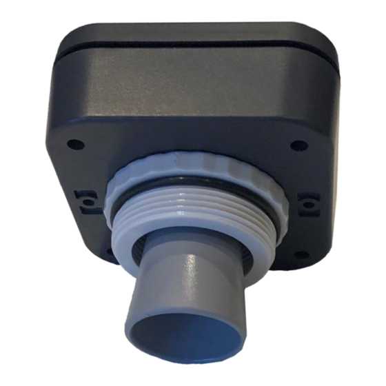
Page 9: Casing
Casing Footprint Mounting Holes Fasteners ACW-LVL can be screwed directly to a tank thanks to its mounting hardware as follows: The external diameter of the mounting hardware is 59 mm and the thread pitch is 2 inches ATIM_ACW-LVL_UG_EN_V0.2.docx... -
Page 10: Product Identification
Product Identification The Sigfox or LoRaWAN IDs of the product are visible on the outside label on the back of the product, inside on the electronic card, and in the status section of the ACW configurator. For LoRaWAN modems, the communication keys are automatically given by the network (pairing by "Over The Air Activation", or OTAA). -
Page 11: Installation And Dismantling
Installation and dismantling It is necessary to open the box to access on the one hand the micro-USB port allowing the configuration of the module. To do this, you must unscrew the four screws which hold the top and bottom of the enclosure together. Screws to dismount the enclosure Installation... -
Page 12: Operating
Operating Operating modes The operating of the ACW-LVL is divided between different modes: Operation mode: this is the default mode when starting the product. In this mode, the module periodically sends measurements according to the configuration applied (if the product has never been configured, the factory configuration applies, see Factory settings). -
Page 13: Product Commissioning
During this phase, a WHITE light signal with a fading effect indicates that the search phase is in progress. If the connection is successful, the product will emit an audible signal and a light signal depending on the quality of the network: •... -
Page 14: Bluetooth Enabling / Disabling
Bluetooth Enabling / Disabling The ACW-LVL incorporates Bluetooth to allow configuration and update of the wireless product. Note Bluetooth functions are only accessible from the operating mode. To know the status of Bluetooth, approach a magnet less than 3 seconds at the diamond marking on the box. The light signal indicates the Bluetooth status as follows: •... -
Page 15: Acw Configurator
Sigfox: V0.0.1 V4.5.8 LoRaWAN: V0.0.1 Download and install the configuration software setup ’setupACW.exe‘ at: http://www.atim.com/docs/downloadcheck.php?ID=3536 When the ACW Configurator is launched, the waiting Click on "Help" at the top left of the window then on window appears on the screen. -
Page 16: Acw-Lvl Setup
ACW-LVL setup Emission period and samples in the frame The transmission period (1) corresponds to the time interval between each sending of a measurement frame. This period can be configured from 10 min to 255 h and its default value is 1 hour. In addition, it is possible to configure the number of samples in a frame (2). -
Page 17: Frame Timestamp
Frame timestamp It is possible to deactivate / activate the time stamping of all radio frames (7) WARNING: This option when activated monopolizes 4 bytes in the frame which cannot be used for useful data. Product clock If the time stamping function is activated, it is essential to configure the internal clock of the product from the configurator, which will retrieve the system clock from the computer to apply it to the product (8). -
Page 18: Factory Settings
Once the configuration is complete, do not leave the module connected via USB. This operating mode is very energy intensive. When you remove the USB link without disconnecting the battery, the module automatically returns to normal operation. Factory settings Radio frames settings: Radio frame emission period: 10 minutes Number of samplings: 1 History depth: 1... -
Page 19: Updates Of Acw
Updates of ACW When connected with Bluetooth Low Energy to the product, it is possible to update the different software that composes it. To do this, go to the menu Tools->Updater (CTRL+U) ATIM_ACW-LVL_UG_EN_V0.2.docx... -
Page 20: Frames Format
Frames format Sigfox and LoRaWAN Uplink frame Byte 1 Byte 2 . . . Byte n Frame header Frame-specific data We can differentiate three types of frames: ⚫ Classic frame; New generation: Very close to the old frames, the difference is that you can activate the timestamp. -
Page 21: Measurement Frame
Different type of frames: Frame type Size of data Descriptions 0x00 Reserved 5 bytes Keep alive frame 0x01 0x02 0 byte Downlink request for network testing 0x03 8 bytes Reserved 0x04 Reserved 0x05 1 byte Test frame with counter 0x06 Variable (Cfg box) Response to a setup frame. -
Page 22: Alert Frame
In the case of ACW-LVL, the measurement type is 0x07 on 2 bytes for the distance in centimeters. In the case of the ACW-LVL, there is only 1 way (i.e. 1 sensor) the channel’s number will always be 0. Type of measurement Units Data size Data type... -
Page 23: Error Frame
Error frame byte 1 - Header Bit7 Bit6 Bit5 Bit4 Bit3 Bit2 Bit1 Bit0 Timestamp Measurement Reserved Error frame generation frame = 0x0e If the Timestamp is activated, 4 bytes with the Timestamp value will be preceded by the header (byte 1). For each error message, a header is inserted and is formed as follows: Error frame header Bit7... -
Page 24: Examples Of Frames
0x10 ERR_SENSORS_FAIL Sensor has stopped to work 0x11 ERR_ARM_INIT_FAIL Radio module initialization has failed 0x12 ERR_ARM_PAYLOAD_BIGGER Message size is too large for network capacity 0x13 ERR_ARM_BUSY The module is already busy (possibly not initialized) 0x14 ERR_ARM_BRIDGE_ENABLE The module is in bridge mode, impossible to send data by radio 0x15 ERR_ARM_TRANSMISSION A transmission has been initialized but an error has occurred... -
Page 25: Alert Frame
Alert frame For exceeding the threshold value defined: Byte 1 Byte 2 Byte 3 Byte 4 0x8D 0x47 0xAF 0x01 (new generation alert frame) (exceeding high threshold channel 0, distance measurement The sample that triggered the threshold on channel 0 is 0x01AF (431 centimeters). ATIM_ACW-LVL_UG_EN_V0.2.docx... -
Page 26: Downlink
The operation of the Downlink is explained in the document ATIM_ACW-DLConfig_UG_FR_v1.4, relating to version V1.2.0 of the ATIM Downlink Protocol (see this document for all parameters and commands common to all products). The parameters specific to ACW-LVL are as follows: Configuration of the frame parameters (sending period, number of samples, etc.) -
Page 27: Threshold Setup
Threshold setup Parameter Frame size Byte 3 Byte 4 Byte 5 Byte 6 Byte 7 Byte 8 Byte 9 code (Byte 1) (Byte 2) 0xD5 0x07 High threshold Low threshold hysteresis Duration For the threshold setup, the byte 0 is the header for an extended downlink frame + the number of the parameter (0xC0 | 0x15). -
Page 28: Technical Support
Technical support For any information or technical problems, you can contact our technical support: www.atim.com/fr/technical-support ATIM_ACW-LVL_UG_EN_V0.2.docx...
Need help?
Do you have a question about the Cloud Wireless LVL Series and is the answer not in the manual?
Questions and answers