
Related Manuals for CORNING RAU5 Series


Summary of Contents for CORNING RAU5 Series
- Page 1 Analog Low Power Remote Unit (RAU5x) User Manual Corning Restricted Co rn in g O ptic a l Com m un icat ions Us er Manual I CMA -482 -AEN I P age 1...
- Page 2 Corning Restricted Co rn in g O ptic a l Com m un icat ions Us er Manual I CMA -482 -AEN I P age 2...
- Page 3 Specifications, and shall be free from defects in material or workmanship (the “Software Warranty”). In the event the Software is proven to be defective under the terms of this Software Warranty, Corning shall correct such defects or failure and ensure that the Software conforms with, and performs the functions set forth in, the Specifications.
- Page 4 Corning shall not be liable for any other damage including, but not limited to, indirect, special or consequential damages arising out of or in connection with furnishing of goods, parts and service hereunder, or the performance, use of, or inability to use the goods, parts and service.
- Page 5 $100,000 for each continuing violation. Patent: http://www.corning.com/worldwide/en/patent-notices.html Corning Restricted Co rn in g O ptic a l Com m un icat ions Us er Manual I CMA -482 -AEN I P age 5...
- Page 6 Hazard Level 1 laser product to IEC/EN 60825-2: 2004 to the same degree. • Corning ONE complies with 21 CFR 1040.10 and 1040.11 except for deviations pursuant to laser notice no. 50 (2007). Corning Restricted Corning O ptic a l Com m un icat ions...
- Page 7 Industrial Boosters may only be used by FCC licensees or those given express (individualized) consent of license. Corning Optical Communications Wireless certifies all of the VARs listed as licensed installers for Corning. For the list of licensed VARs, please contact the Tech Support Hotline: (US) 410-553-2086 or 800-787-1266.
- Page 8 This user guide provides all the information necessary to understand the architecture and general installation procedures and requirements of the Corning optical network evolution (ONE) solutions convergence infrastructure five-band remote access unit (RAU5x) and plug-in add-on modules, optionally assembled in the RAU enclosure (hot pluggable): •...
-
Page 9: Table Of Contents
Fiber Optic Requirements ........................... 29 3.7.1 Authorized Optic Cables ........................29 3.7.2 Fiber Optic Rules ..........................29 Corning Restricted Co rn in g O ptic a l Com m un icat ions Us er Manual I CMA -482 -AEN I P age... - Page 10 Verify Normal Operation ..........................59 RAU5x/RxU2325 Cavity Filter Installation ..........61 5.1.1 Package Contents ........................... 62 Corning Restricted Co rn in g O ptic a l Com m un icat ions Us er Manual I CMA -482 -AEN I P age...
- Page 11 Cavity Duplexer for LTE 700 MHz ....................... 81 Cavity Duplexer for 800 MHz ........................82 Gigabit Ethernet Module (GEM) ........................83 Corning Restricted Co rn in g O ptic a l Com m un icat ions Us er Manual I CMA -482 -AEN I P age...
- Page 12 Appendix D: Ordering Information ............84 Accessories ................................. 84 Corning Restricted Co rn in g O ptic a l Com m un icat ions Us er Manual I CMA -482 -AEN I P age...
-
Page 13: Introduction
Note: RAU5x can be ordered with a preassembled Corning external antenna or can be connected to external omni directional or directional antennas complying with the requirements specified in Section 3.6.1. -
Page 14: Architecture
(OIU) at the headend. Signals are automatically filtered, amplified and distributed via external antennas. Uplink signals are then converted to optical signals before being transmitted back to the OIU. Figure 1-1. Example of Corning Optical Network Evolution (ONE) Solutions Deployment Acronyms... -
Page 15: Web Management Application
1.3 Web Management Application ™ The Corning Optical Network Evolution (ONE ) Solution headend control module (HCM) enables centralized, system-level element management and provides comprehensive end-to-end, single source setup and management of the active RF system components after their physical installation. Management capabilities are provided for both the RAU5x and installed RF expansion module. -
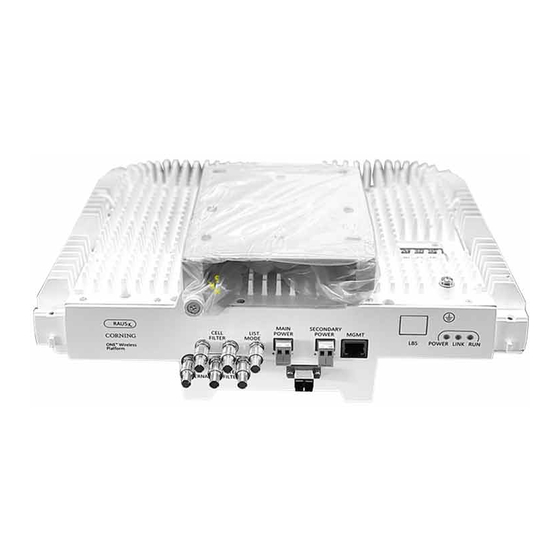
Page 16: Interfaces
• Specific RAU5x models are available with provided external antenna enclosure. GND Bolt Figure 2-1. RAU5x: Interfaces Corning Restricted Co rning O ptic al Com m unicat ions Us e r Manu al I CMA -482 -AE N I P a ge 1 6... - Page 17 GROUNDING BOLT 8-32 x 3/8 grounding screw used for connecting RAU5x to earth ground Corning Restricted Co rn in g O ptic a l Com m un icat ions Us e r Manual I CMA -482 -AE N I P age 1 7...
- Page 18 Off — no power supplied to unit Table 2-2. LED Descriptions Corning Restricted Co rn in g O ptic a l Com m un icat ions Us e r Manual I CMA -482 -AE N I P age 1 8...
-
Page 19: Rxu2325
QMA RF ports for external cavity filter use (if required by site planner). For CELL and LTE filters. Table 2-3. RxU2325 Interface Connections Corning Restricted Co rn in g O ptic a l Com m un icat ions Us e r Manual I CMA -482 -AE N I P age 1 9... -
Page 20: Rxu67
PWR LED Indicates power ON. Table 2-4. RxU67 Front Panel Interface Connections Corning Restricted Co rn in g O ptic a l Com m un icat ions Us e r Manual I CMA -482 -AE N I P age 2 0... -
Page 21: Gem
Ethernet fiber switch Table 2-5. GEM Port Interfaces Corning Restricted Co rn in g O ptic a l Com m un icat ions Us e r Manual I CMA -482 -AE N I P age 2 1... - Page 22 Blinking yellow: Activity Off: No activity Table 2-6. GEM LED Indicator Descriptions Corning Restricted Co rn in g O ptic a l Com m un icat ions Us e r Manual I CMA -482 -AE N I P age 2 2...
-
Page 23: Installation Guidelines
• Follow electro-static discharge (ESD) precautions. • Use low loss cables to connect the antennas Corning Restricted Co rn in g O ptic a l Com m un icat ions Us e r Manual I CMA -482 -AE N I P age 2 3... -
Page 24: Power Requirements
1600 1200 1100 1100 14AWG 3500 3100 2650 2010 1800 1800 Table 3-3. Required Cable Gauge Corning Restricted Corning O ptic a l Com m unicat ions Us er Manual I CMA -482 -AE N I P age 2 4... -
Page 25: Power, Heat And Rack Specifications
*Min/Max VDC = 37/57 @ 1.49 Amps, 85% efficiency Table 3-5. Remote End Distance and Power Draw for (Standalone) RAU5x SISO Corning Restricted Co rn in g O ptic a l Com m un icat ions Us e r Manual I CMA -482 -AE N I P age 2 5... - Page 26 *Min/Max VDC = 52/57 @ 1.49 Amps, 85% efficiency Table 3-8. Remote End Distance and Power Draw for GEM w/PoE.3at Corning Restricted Co rn in g O ptic a l Com m un icat ions Us e r Manual I CMA -482 -AE N I P age 2 6...
-
Page 27: Power Safety Instructions
• Use coax RG-223, 50 ohm, male-to-male N-type to QMA for RF connections from the RIMs to the BTS/RBS and to the RAU5xs. • When using the Corning system in an environment in which other indoor coverage systems are installed, it is recommended (where possible) that the antennas are placed at least two meters apart •... -
Page 28: Coax Cable Lengths And Losses
Total Loss Loss (900 MHz) Table 3-9. Coax Cable Lengths and Losses Corning Restricted Co rn in g O ptic a l Com m un icat ions Us e r Manual I CMA -482 -AE N I P age 2 8... -
Page 29: Antenna Specifications And Guidelines
• Do not crush the cable or allow it to kink. Doing so may cause damage that can alter the transmission characteristics of the cable. The cable may have to be replaced. Corning Restricted Co rn in g O ptic a l Com m un icat ions... -
Page 30: Power Safety Instructions
• Install external over-current protective devices for the system according to the requirements described in section 3.4.6. Types of Power Supplies Corning supplies various enclosed power supplies (i.e., ICU and PSU6) that can be installed in a rack or mounted on a wall, depending on your configuration. -
Page 31: Installation
For this scenario, refer to the on-site expansion instructions. In each step, refer to the instructions relevant to your specific site deployment Note: For specific guidelines on infrastructure planning, design and installation, please consult with a Corning product line manager or Corning approved Installer. -
Page 32: Verify Package Contents
• For RxU67 add-on installation, see Connect an RxU67 to the RAU5x • For RxU2325 add-on installation, see Connect RxU2325 and/or GEM to the RAU5x Corning Restricted Corning O ptic a l Com m unicat ions Us er Manual I CMA -482 -AE N I P age 3 2... -
Page 33: Mount The Rau5X
Table 4-2. RAU5x Mounting Options Corning Restricted Co rn in g O ptic a l Com m un icat ions Us e r Manual I CMA -4 82 -AE N I P age 3 3... -
Page 34: Standard Standoff Mount Installation
Note: The RAU5x connectors should face the standoff mount captive screw. Figure 4-2. Example of Standoff Mount Installation on Wall Corning Restricted Co rn in g O ptic a l Com m un icat ions Us e r Manual I CMA -482 -AE N I P age 3 4... -
Page 35: For Green-Field Installation With Rxu67
Note: 80 Watt is required. If needed, use the secondary power connection to comply. • Fiber pairs (Corning® SMF-28® fiber or compatible): One fiber pair for RAU module • Grounding wire: refer to RAU UM, and connect the earth ground to the unit’s 8-32 x 3/8 grounding screw 2. -
Page 36: Mount The Rau5X Onto The Standoff Mount
3. Lock RAU5x pins into the narrow ends of the standoff mount keyholes. Figure 4-4. Examples of Mounting RAU5x onto Bracket: wall mount; ceiling mount with RxU67 cavity filter Corning Restricted Co rn in g O ptic a l Com m un icat ions... - Page 37 5. Using the supplied security cable, attach the RAU5x to a permanent structure within the ceiling (e.g., acoustic ceiling grid or concrete ceiling above). Corning Restricted Co rn in g O ptic a l Com m un icat ions Us e r Manual I CMA -4 82 -AE N I P age 3 7...
-
Page 38: Top Bracket (Mid-Mount Installation)
Dimensions for “Top Bracket” dimensions. Figure 4-6. “Top Bracket” Assembly Lift Bracket and Plate Corning Restricted Co rn in g O ptic a l Com m un icat ions Us e r Manual I CMA -482 -AE N I P age 3 8... -
Page 39: Installing Bracket Assembly And Mounting Rau5X
4.3.2.2 Installing Bracket Assembly and Mounting RAU5x Note: The figures in this section, illustrate the top bracket installation with an RAU5x which includes the Corning external antenna. To install bracket and mount RAU5x 1. Install the plate in the ceiling and using the two safety cables, pre-connected to the middle safety rings of the plate, secure to secure to a permanent structure. - Page 40 Note: Lift Bracket captive screw must face the RAU5x connectors. Figure 4-9.Mounting RAU5x onto Lift Bracket Corning Restricted Co rn in g O ptic a l Com m un icat ions Us e r Manual I CMA -482 -AE N I P age 4 0...
- Page 41 5. MANDATORY! Secure RAU5x using the attached safety cable to a permanent structure. Figure 4-11. Securing RAU5x to Permanent Structure Corning Restricted Co rn in g O ptic a l Com m un icat ions Us e r Manual I CMA -4 82 -AE N I P age 4 1...
- Page 42 6. Push up and pull down Lift Bracket into plate and verify that connection cables are not subject to kinking. Note: The installer is solely responsible for proper cable wiring and routing of the RAU5x unit per instructions provided in relevant Corning documentation. Figure 4-12 Verifying that Cable Path is not Obstructed 7.
- Page 43 Figure 4-14. Complete Assembled RAU5x Note: Refer to Section 4.3.2.3for RAU5x top bracket cap assembly (kit ordered separately) for RAU5x units without Corning external antenna. Corning Restricted Co rn in g O ptic a l Com m un icat ions...
-
Page 44: Top Bracket Cap Assembly
4.3.2.3 Top Bracket Cap Assembly This section provides instructions on how to assemble the cap onto an installed RAU5x and “Top Bracket” assembly which does not include the Corning plug-in external antenna. Note the following: • Cap, RAU5x and Top Bracket are each ordered separately. - Page 45 ATTENTION! The site engineer or contracted installer is responsible for all safety issues and procedures on-site! Figure 4-17. Hooking Narrow Fasteners in Place Corning Restricted Corning O ptic a l Com m unicat ions Us er Manual I CMA -4 82 -AE N I P age 4 5...
- Page 46 Refer to following figures for instructions on how to remove cap in order to access the RAU5x. Figure 4-18. Removing Cap Corning Restricted Co rn in g O ptic a l Com m un icat ions Us e r Manual I CMA -482 -AE N I P age 4 6...
-
Page 47: Wall Bracket Mount
Drilling template – used for marking holes for drilling Table 4-3. BR-RAU5US-WALL Kit Package Items Corning Restricted Corning O ptic a l Com m unicat ions Us er Manual I CMA -4 82 -AE N I P age 4 7... -
Page 48: Installing Wall Mount Bracket And Mounting Rau5X
Figure 4-19. Required 3-Inch Clearance from Surface Corning Restricted Co rn in g O ptic a l Com m un icat ions Us e r Manual I CMA -482 -AE N I P age 4 8... - Page 49 3. Hang bracket on anchors and tighten. Figure 4-21. Mounting and Securing Bracket to Anchors Corning Restricted Co rn in g O ptic a l Com m un icat ions Us e r Manual I CMA -4 82 -AE N I P age 4 9...
- Page 50 5. For Second RAU5x – mount on second standoff mount and close captive screw to secure RAU5x to bracket. Figure 4-23. Mounting and Securing Second RAU5x Corning Restricted Co rn in g O ptic a l Com m un icat ions...
- Page 51 6. Open and close bracket door to verify clearance for routing and connecting cables. Note: Installer is solely responsible for proper cable wiring and routing of the RAU5x unit per instructions provided in relevant Corning documentation. 7. Lock wall-mount bracket door.
-
Page 52: Connect The Cables
Another pair for “Secondary Power” connection depends on cable AWG and distance from power source, and is according to calculation before the deployment. The RAU will raise an alarm when not enough power to turn on the RxU67. • Fiber pairs (Corning SMF-28 ®... -
Page 53: Connect The Cables
Connect the earth ground to the unit’s 8-32 x 3/8 grounding screw. See Figure 4-25 for location of ground connection. Figure 4-25. RAU5x Grounding and optical fiber pair Connection Corning Restricted Corning O ptic a l Com m unicat ions Us er Manual I CMA -4 82 -AE N I P age 5 3... -
Page 54: Optical Fiber Connection
• RAU5x + RxU67: 44.5 V; 73 W NOTE: Connect the 2nd DC wire pair when there is not enough power! Corning Restricted Co rn in g O ptic a l Com m un icat ions Us e r Manual I CMA -482 -AE N I P age 5 4... - Page 55 Figure 4-26 RAU5x Main Power DC Connections Corning Restricted Co rn in g O ptic a l Com m un icat ions Us e r Manual I CMA -4 82 -AE N I P age 5 5...
-
Page 56: Rf Connections
Connect optic fiber pair to RAU5x module LC APC optic connector. See Figure 4-28. Figure 4-28. Ground, Fiber and RF Cable Connections for RAU5x Corning Restricted Co rn in g O ptic a l Com m un icat ions Us e r Manual I CMA -482 -AE N I P age 5 6... - Page 57 Figure 4-29. RF Connections for RAU5x with RxU2325 • If required by site planner – perform (QMA) UL/DL external connections to external filters. Corning Restricted Co rn in g O ptic a l Com m un icat ions Us e r Manual I CMA -4 82 -AE N I P age 5 7...
- Page 58 Note: A and B ports – 10/100/1000 BASE-T with 802.3at compliant Power over Ethernet (PoE+) PSE ports. Figure 4-31. GEM Interface Connections Corning Restricted Co rn in g O ptic a l Com m un icat ions Us e r Manual I CMA -482 -AE N I P age 5 8...
-
Page 59: Antenna Connections
4.4.2.5 Antenna Connections For RAU5x models not including Corning external antenna: 1. Connect the RAU5x QMA “Ext. Ant.” connector to the external antenna, as illustrated in Figure 4-32. Note: for RAU5x units installed with RxU2325, the external antenna is connected to the RxU2325 “ANT.” port. - Page 60 Figure 4-34. RxU2325 Status LED Location Corning Restricted Co rn in g O ptic a l Com m un icat ions Us e r Manual I CMA -482 -AE N I P age 6 0...
-
Page 61: Rau5X/Rxu2325 Cavity Filter Installation
• For acoustic ceiling installations – use provided safety cable to secure the filter assembly to a permanent structure within the ceiling (e.g., acoustic ceiling grid or concrete ceiling above). Corning Restricted Co rn in g O ptic a l Com m un icat ions... -
Page 62: Package Contents
5.1.1 Package Contents Check your package contents to verify that the items in the packing list are included. If any of the listed items are missing, contact your Corning representative. Item Description Quantity Cavity Filter CVT800 - 836.5MHz; 0.5W; 824-849MHz;... -
Page 63: Acoustic Ceiling Mount Installation
6. Drill the holes in the wall corresponding to the diameter of the anchors to be used (not provided). Figure 5-4. Marking and Inserting Anchors in Wall Corning Restricted Co rn in g O ptic a l Com m un icat ions... - Page 64 7. Hang the Cavity Filter on the anchors/screws and pull down to lock in narrow end of key hole. Refer to Figure 5-5. Figure 5-5. Mounting Cavity Filter on Wall Corning Restricted Co rn in g O ptic a l Com m un icat ions...
-
Page 65: Filter Connections
Figure 5-6. Example of RAU5x External CELL Filter Connections Figure 5-7. Example of RAU5x and RxU External LTE Filter Connections Corning Restricted Co rn in g O ptic a l Com m un icat ions Us e r Manual I CMA -4 82 -AE N I P age 6 5... -
Page 66: Appendix A: Bracket Dimensions
6 APPENDIX A: BRACKET DIMENSIONS Standoff Mount Figure 6-1. Standoff Mount Dimensions Corning Restricted Co rn in g O ptic a l Com m un icat ions Us e r Manual I CMA -482 -AE N I P age 6 6... -
Page 67: Top Bracket
Top Bracket Figure 6-2 RAU5x Top Bracket Dimensions Corning Restricted Co rn in g O ptic a l Com m un icat ions Us e r Manual I CMA -482 -AE N I P age 6 7... -
Page 68: Wall- Mountable Bracket
Wall- Mountable Bracket Figure 6-3. RAU5x Wall-Mountable Bracket Dimensions Corning Restricted Co rn in g O ptic a l Com m un icat ions Us e r Manual I CMA -482 -AE N I P age 6 8... - Page 69 Note: The drilling pattern template is provided with the wall-mountable bracket kit (P/N: BR-RAU5US-WALL). Figure 6-4. RAU5x Wall-Mountable Drilling Pattern Dimensions Corning Restricted Co rn in g O ptic a l Com m un icat ions Us e r Manual I CMA -482 -AE N I P age 6 9...
-
Page 70: Appendix B: Upgrades
• RXU67 Cable kit ,800mm, QMA o QMA, for rear, side, top mount /MIMO bracket installation Table 7-1 RxU67 Package Contents Corning Restricted Corning O ptic a l Com m unicat ions Us er Manual I CMA -482 -AE N I P age 7 0... -
Page 71: Rxu2325 Package
• For RAU5x units with assembled broadband antenna – open antenna by pushing in on the pins on both sides of the antenna cover and pulling on the side handles, as show in Figure 7-1. Corning Restricted Corning O ptic a l Com m unicat ions Us er Manual I CMA -482 -AE N I P age 7 1... - Page 72 Figure 7-1. Opening RAU5x Antenna Corning Restricted Co rn in g O ptic a l Com m un icat ions Us e r Manual I CMA -482 -AE N I P age 7 2...
-
Page 73: Connect Rxu2325 And/Or Gem To The Rau5X
• With external antennas from other vendor - connect RxU “EXT. ANT.” QMA connector to an external antenna for MIMO coverage • With Corning external antenna – connect RxU “EXT. ANT.” QMA connector to the external antennas’ “RxU” QMA port using RF jumper. -
Page 74: Connect An Rxu67 To The Rau5X
3. Use a Philips screwdriver to secure the RxU67 to the RAU5x by fastening four captive screws. Figure 7-3. Attach RxU67 to RAU5x Corning Restricted Corning O ptic a l Com m unicat ions Us er Manual I CMA -482 -AE N I P age 7 4... -
Page 75: Assemble The Cavity Filter
Note: ensure the filter’s connectors are facing the same direction as the RAU and RXU connectors! Figure 7-4. Select position for the cavity filter Corning Restricted Corning O ptic a l Com m unicat ions Us er Manual I CMA -482 -AE N I P age 7 5... - Page 76 Figure 7-6. Slide bracket on shoulder screws & Secure Corning Restricted Co rn in g O ptic a l Com m un icat ions Us e r Manual I CMA -482 -AE N I P age 7 6...
- Page 77 Note: Ensure the RAU connectors are facing the same direction as the RAU connectors! Figure 7-7. Securing Bracket assembled to Cavity filter Corning Restricted Co rn in g O ptic a l Com m un icat ions Us e r Manual I CMA -482 -AE N I P age 7 7...
-
Page 78: Appendix C: Specifications
§20 dBm if only one of the services is operating. ** Insertion loss from RxU2325 combiner (if installed) = 0.5/1.0 dB. Corning Restricted Co rn in g O ptic a l Com m un icat ions Us e r Manual I CMA -482 -AE N I P age 7 8... -
Page 79: Optical
2. GEM; Giga bit Ethernet module – upgrade module for the RAU5x. One module per RAU5xGEM; Corning Restricted Co rn in g O ptic a l Com m un icat ions Us e r Manual I CMA -482 -AE N I P age 7 9... - Page 80 RAU5x and RxU/RxU2325 and GEM only: 14.39 lbs (6.5 kg) External Antenna: 3.7 lbs (1.7 kg) Corning Restricted Co rn in g O ptic a l Com m un icat ions Us e r Manual I CMA -482 -AE N I P age 8 0...
-
Page 81: Remote Expansion Unit (Rxu67)
Passband Ripple 0.8 dB (Maximum) Return Loss (Minimum) 18.0 dB, all ports Corning Restricted Co rn in g O ptic a l Com m un icat ions Us e r Manual I CMA -482 -AE N I P age 8 1... -
Page 82: Cavity Duplexer For 800 Mhz
50 Ohms Nominal Impedance -20 ◦ C to +85 ◦ C Operating Temperature Corning Restricted Co rn in g O ptic a l Com m un icat ions Us e r Manual I CMA -482 -AE N I P age 8 2... -
Page 83: Gigabit Ethernet Module (Gem)
(32.7 x 96.3 x 151.3 mm) Weight: 1.1 lbs (0.5 kg) Corning Restricted Co rn in g O ptic a l Com m un icat ions Us e r Manual I CMA -482 -AE N I P age 8 3... - Page 84 BR-RAU5US-CAP installations including RAU5/RAU5x without Corning external antenna Corning Optical Communications LLC • PO Box 489 • Hickory, NC 28603-0489 USA 800-743-2675 • FAX: 828-325-5060 • International: +1-828-901-5000 • www.corning.com/opcomm Corning Optical Communications reserves the right to improve, enhance, and modify the features and specifications of Corning Optical Communications products without prior notification.
Need help?
Do you have a question about the RAU5 Series and is the answer not in the manual?
Questions and answers