Table of Contents
Advertisement
Quick Links
Advertisement
Table of Contents

Related Manuals for ANTUMBRA ROT8

Summary of Contents for ANTUMBRA ROT8
- Page 1 ANTUMBRA ROT8 MANUAL...
-
Page 2: Table Of Contents
TABLE OF CONTENTS 01. INSTALLATION 02. BACK 03. FRONT 04. SEQUENCE 05. DIRECTION 06. GATE PAGE 07. STEP SETTINGS 08. GATE MODE 09. SEQUENCE LENGTH PAGE 10. SEQUENCE RESET PAGE 11. TUNE PAGE 12. GATE LENGTH PAGE 13. ASSIGN MENU 14. - Page 3 00. THANK YOU! Thank you for purchasing the Antumbra ROT8 module! In this documentation you can find information about the installation and use of the module, also an assembly in- struction if you bought the DIY version.
-
Page 4: Installation
01. INSTALL ATION When you turn the ROT8 around, you should see the mod- ule as it is on the left illustration. Plug in the power cable to the power cable header pins, but BE CAREFUL with the orientation of the cable! The RED STRIPE should be on the BOTTOM of the module, indicated by the white line below the header pins. -
Page 5: Back
02. BACK On the back there are two jumpers that can be set. The top one selects the maximum voltage that goes in the pots, to the output, this can be set to 5V or 12V. The bottom one enables or disables the jack lights. -
Page 6: Front
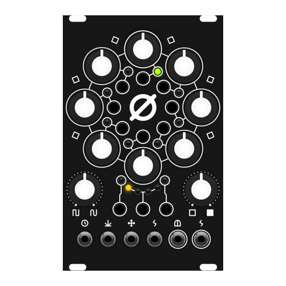
03. FRONT 1-8 POTS, LEDS AND BUTTONS PER STEP (refered to as knob 1, LED 1, button 1, etc.) 9 SLEW POT 10 ASSIGNABLE POT 11 CLOCK IN JACK (0-12V) 12 RESET IN JACK (0-12V) 13 DIRECTION CV IN JACK (0-5V) 14 ASSIGNABLE CV IN JACK (0-5V) 15 GATE OUT JACK (0-5V) 16 CV OUT JACK (0-5V or 0-10V) -
Page 7: Sequence
04. SEQUENCE The sequence is set by potentiometers 1-8, the value of the active step (indicated by green LED on LEDs 1-8) is output on the CV out jack. The output path is fully analog, so there’s no quantization on the output. -
Page 8: Direction
05. DIRECTION Direction is indicated by LEDs B1-4, and are cycled by pressing the B button, or feeding CV into the direction CV in jack. The directions from left to right are the following: B1 Forward (clockwise) B2 Backward (counter clockwise) B3 Pendulum B4 Random... -
Page 9: Gate Page
06. GATE PAGE Gate page is indicated by A and C LEDs being turned off. You can enter a gate per step by pressing buttons 1-8. Active gates are represented by red LEDs on each step. When the sequence reaches a step with a gate set to on, it’ll output a gate signal on the gate output jack. -
Page 10: Step Settings
07. STEP SE T TINGS Step settings are accessed by long pressing a step button. The selected step will blink. Buttons in this mode select the number of repeats on the selected step from 1-8, this allows you to expand the sequence to more than 8 steps. To exit the step settings press the selected value one more time. -
Page 11: Gate Mode
08. GATE MODE In step settings, button B cycles through gate modes for the step. The step will only produce gates if it is enabled on the gate page. The four gate modes are: B1 SINGLE TRIGGER (default): There is a single gate output on the step, repeats after it won’t produce gates. -
Page 12: Sequence Length Page
09. SEQUENCE LENGTH PAGE Sequence length page is accessed by pressing button C, and is indicated by LED C lighting up. On this page you can set the length of your sequence by pressing the step buttons. After the last selected step, the sequence will start again from step 1. -
Page 13: Sequence Reset Page
10. SEQUENCE RESE T PAGE Sequence reset page is accessed by long pressing button C, and is indicated by LED C blinking. If repeats are enabled, the sequence can go beyond 8 steps, and will likely consist of even steps. On the se- quence reset page you can constrain the sequence to the following measures with the step buttons: no constrain, 4, 8, 16, 32, 64, 128, 256... -
Page 14: Tune Page
11. TUNE PAGE You can access the tune page by long pressing on button A, and is indicated by LED A blinking. When you access the tune page, the sequence is paused, and you can change steps by pressing the step buttons. This is great if you want to tune the knobs to certain po- sitions. -
Page 15: Gate Length Page
12. GATE LENGTH PAGE Gate length page is accessed by long pressing button C, and is indicated by LED C blinking. Here you can set the gate length with the step buttons. Gate length is a percentage value calculated from the time between two clock inputs. -
Page 16: Assign Menu
13. A SSIGN MENU Assign menu is accessed by long pressing button B, B1 and B2 LEDs light up. You can switch between CV assign- ment (B1 & B2 LEDs) and pot assignment (B3 & B4 LEDs) by pressing button B while in this mode. Leave this page by long pressing on button B again. -
Page 17: Slew
14. SLE W The voltage from the step pots are sent through an analog slew circuit, and then to the output. Slew smooths the transition between two values, creating glides. Full counter-clockwise there is no glide effect at all, while fully clockwise, the transition between two steps is slowed down. -
Page 18: Reset To Default
15. RESE T TO DEFAULT To reset the module to it’s default settings, long press button A and C, till the B LEDs blink. Default settings are: Gate steps: cleared Repeats: Gate mode: single trigger Sequence length: 8 steps Sequence reset: no reset Gate time: CV assign:... -
Page 19: Software Modifications
16. SOF T WARE MODIFIC ATIONS Feel free to modify the software of your module, but at your own risk! Antumbra doesn’t take responsibility for damaged microcontrollers, if you proceed from here I as- sume you know what you are doing. - Page 20 ROT8 is designed by David Szebenyi under Antumbra. www.antumbra.eu Manual by David Szebenyi (www.aman.hu) 2017 • All rights reserved!
Need help?
Do you have a question about the ROT8 and is the answer not in the manual?
Questions and answers