
Related Manuals for Rugby LR-3510


Summary of Contents for Rugby LR-3510
- Page 1 RUGBY MANUFACTURING CO. INDUSTRIAL PARK 515 1st St. NE. RUGBY, NORTH DAKOTA 58368 1656589 LR-3510 Install and Operation Manual LATEST EDITION: July 24, 2020 FIRST EDITION: January 4, 2001...
- Page 2 LR-3510 Stock No. 1656589 Page 2 of 9 WARNINGS: Warning: Not installing or operating equipment correctly can cause component damage or an accident which may cause injury or death. "Always" install and operate equipment in accordance with manufacturer's instructions. Read and understand this manual fully before proceeding.
-
Page 3: Section A - Application
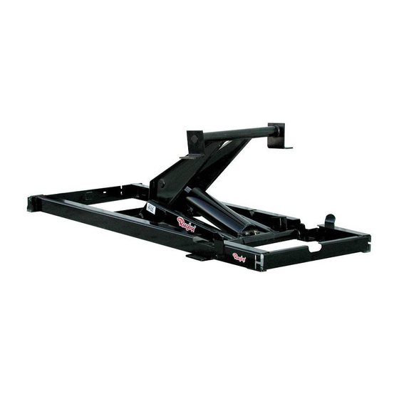
SECTION A – APPLICATION The capacity and dump angle obtained with the LR-3510 will vary depending on where the hoist is mounted in relation to the rear hinge, see Table A. Below is a list of dump angles and corresponding capacities for different mounting distances (M), (Refer to Fig. -
Page 4: Section B - Installation Of Rear Hinge
LR-3510 Stock No. 1656589 Page 4 of 9 SECTION B - INSTALLATION OF REAR HINGE: Determine the location of the rear hinge. This location should be immediately behind the rear wheel leaf spring shackle. Referring to Fig. #2, cut a notch as shown. -
Page 5: Section C -- Installation Of Hoist Frame
Locate the hoist on the truck frame, making sure to center the hoist right and left, and to square the hoist with the truck frame. The LR-3510 is designed to rest on the truck frame as shown in Fig. #1. -
Page 6: Section E - Body Installation
(just long beams if they are separate from the body) onto the truck frame. NOTE: A clearance of at least 2" is required between the truck cab and the closest point on the truck body. The LR-3510 has a mounting height of 5". -
Page 7: Section F -- Lubrication
LR-3510 Stock No. 1656589 Page 7 of 9 NOTE: On some models of trucks, the frame is not flat from front to rear. On these models, provisions must be made to level the frame before installing the body. Position the rear hinge brackets against the long beams. Once in position, weld the rear hinge brackets to the body long beams. - Page 8 FITTING, ¼-28” THREAD FORMING GREASE 1654011 PIN, ¼” X 1-3/4” ROLL 1655043 ANGLE, MOUNTING 1655082 SHAFT, CYLINDER PIN 1655176 LOCK RING 1655198 BRACKET, LR-3510 LIFT 1655199 SET, LR-3510 SADDLE BRACKET 1655479 SHAFT, CYL. PNG 1655885 FRAME ONLY LR-3510 1621263 CYLINDER, 3.5 X 10, O-RINGS...
- Page 9 This will lock the truck body against the truck frame. WARNING: Anytime the hoist or truck body is worked on with the truck body in a raised position, be sure the unloaded body is properly blocked with the body prop or body props. ©2001 Rugby Manufacturing Co.
Need help?
Do you have a question about the LR-3510 and is the answer not in the manual?
Questions and answers