Table of Contents
Advertisement
Quick Links
Advertisement
Table of Contents

Related Manuals for PXM PX 235


Summary of Contents for PXM PX 235
- Page 1 PX 235 Advanced DMX Multiplexer MANUAL...
-
Page 2: Table Of Contents
10. Technical Data........................11. Declaration of conformity....................Manufacturer reserves the right to make modifications in order to improve device operation. PXM Marek Żupnik spółka komandytowa tel.: (+48 12) 626 46 92 ul. Przemysłowa 12 fax: (+48 12) 626 46 94 30-701 Kraków... -
Page 3: General Description
1. GENERAL DESCRIPTION Advanced DMX Multiplexer is a complex device that allows to change analog signal 0- 10V to the DMX-512 signal. Analog signal is converted into a digital signal and then it is inserted or replaced at the appropriate (chosen by the user) DMX channel from the DMX- 512 package. -
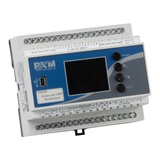
Page 4: Description Of The Connectors And Control Elements
3. DESCRIPTION OF THE CONNECTORS AND CONTROL ELEMENTS DMX-512 Input DMX-512 Output Power supply LCD Screen Control outputs Control buttons USB input 0-10V Inputs 4. NAVIGATING THE MENU Navigating the menu allow programmable buttons. Every button is described on the right side and their use is as follows: - allows to enter the selected option and approve set value - scrolls up the menu or right (horizontal menu) - scrolls back the menu or left (horizontal menu) -
Page 5: Summary Screen
5. SUMMARY SCREEN When you turn the device appears on the screen panel, which describes the current state of DMX signal. If the device takes the DMX signal is green displays Signal OK In case of no DMX signal detected at the input to the device on the screen will be showed message No DMX Signal Description of the other messages on the Summary screen:... -
Page 6: Programming The Device Functions
The presentation of the DMX signal: The value of DMX signal to the frame (DMX channel) is portrayed as a white column, whose height varies proportionally according to the formula: the highest = largest value of DMX signal - 255, no column = no DMX signal, value is 0. Number of frame (DMX channel) is described on the left, respectively: 1, 129, 257, 385 for subsequent lines. - Page 7 1.Break Time allows to change the length of the interval between successive DMX packets. Break signal may take longer, but can not be less than 120 microseconds. Usually it lasts about 120-140 microseconds. At the top of the screen next to the option name are visible important information that simplify setting an appropriate...
-
Page 8: Firmware Info
7.2. FIRMWARE INFO In this submenu you can check the firmware installed on the device. You can also restore the default settings implemented on the device. To do this push enter , then select the button and again approve with enter. In the case of incorrect choosing this option, you can go back by selecting , or go directly level up in menu by pressing escape. -
Page 9: Wind Speed > Dmx
7.4. WIND SPEED > DMX Wind speed onto the DMX is a function that allows you to set parameters of conversion of the voltage signal from the anemometers to values compatible with DMX protocol. To set the limit values You need to approve with the enter the set button on the screen and follow the point 4 on page 2. -
Page 10: Counter Input Settings
7.6. COUNTER INPUT SETTINGS Counting Input Settings menu allows to change some values and the characteristic parameter of the anemometer (Transducer output) of formula 1 [Hz] = x [m / s]. The default is set to 0.1 [m / s], but be sure to check this parameter and (if needed) to change after connection of the new anemometer. -
Page 11: Language Settings
7.8. LANGUAGE SETTINGS Language Settings allows you to change the menu language. To do this select appropriate language with previous next buttons and press enter 8. CONNECTIONS DIAGRAM a) CONNECTION TO POTENTIOMETERS POTENTIOMETERS 0 - 10V IN 0 - 10V IN +10V OUT D C O K power supply... - Page 12 b) 0 - 10V control 0 - 10V SINGAL SOURCES 0 - 10V IN 0 - 10V IN 0 - 10V IN 0 - 10V IN Caution! Do not connect DMX input and output pins parallel. See paragraph 9 of the manual. D C O K power supply 12-24 V DC...
-
Page 13: Dimensions
10. DIMENSIONS 60 mm 105 mm 11. TECHNICAL DATA - Power Supply 12 - 24V DC - DMX Input - DMX Output - 0-10V Inputs - 10V Output 1 (to power supply ex. potentiometers) - OC Type Output - Connectors Clamping screws, USB - Weight 0,2kg... -
Page 14: Declaration Of Conformity
30-701 Kraków, Poland fax: +48 12 626 46 94 DECLARATION OF CONFORMITY according to guide lines 2004/108/EC Name of producer: PXM Marek Żupnik sp. k. Address of producer: ul. Przemysłowa 12 30-701 Kraków, POLAND declares that the product: Name of product:...
Need help?
Do you have a question about the PX 235 and is the answer not in the manual?
Questions and answers