Table of Contents
Advertisement
Quick Links
Advertisement
Table of Contents

Subscribe to Our Youtube Channel
Related Manuals for PXM PX235


Summary of Contents for PXM PX235
- Page 1 PX235 0-10V/DMX Interface 8ch User manual...
-
Page 2: Table Of Contents
Table of Contents 1 Description....................4 2 Safety conditions..................5 3 Connectors and control elements............6 4 Navigating the menu..................6 5 Summary screen..................7 6 Main menu....................8 7 Programming the device functions............9 7.1 DMX Out Settings..................... 10 7.1.1 Break Time......................10 7.1.2 MAB Time......................11 7.1.3 MBF Time...................... - Page 3 Manufacturer reserves the right to make modifications in order to improve device operation. PXM Marek Żupnik sp.k. Podłęże 654 tel. +48 12 385 83 06 32-003 Podłęże mail: info@pxm.pl Rev.1-5 BDO register number 000005972 www.pxm.pl 03.02.2020...
-
Page 4: Description
DMX512 package, to which the processed signal is insert. The PX235 has one DMX signal input and output. The built-in color display makes it easier to operate the device, as well as the graphical representation of the signal status and thus allows its control. -
Page 5: Safety Conditions
Safety conditions Multiplexer PX235 is a device powered with safe voltage12 – 24V DC, however, during its installation and use the following rules must be strictly observed: 1. The device may only be connected to 12 – 24V DC (stabilized voltage) with current-carrying capacity compatible with technical data. -
Page 6: Connectors And Control Elements
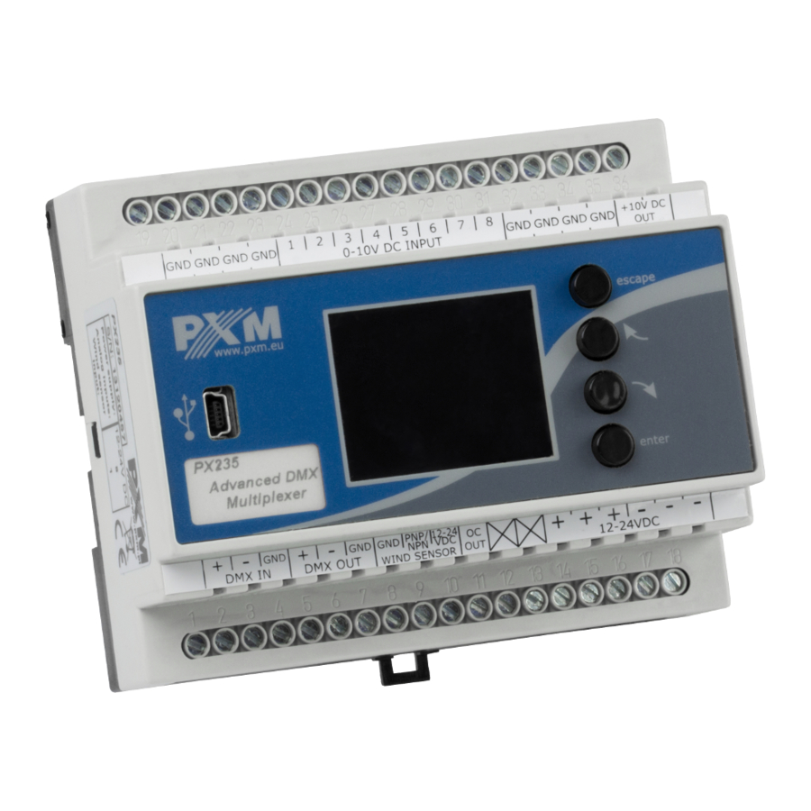
Connectors and control elements DMX-512 Input DMX-512 Output Power supply LCD screen Wind sensor and alarm output support block Control buttons USB Input 0-10V Inputs Reference voltage +10V (for power supply e.g. potentiometers) Navigating the menu Navigating the menu allow programmable buttons. Every button is described on the right side and their use is as follows: –... -
Page 7: Summary Screen
After that you need to save the settings before going level up, this will allow storing value in memory of the PX235. To do this, after moving to the screen button you need to push enter button. -
Page 8: Main Menu
Out OFF / ON – information regarding the status of alarm output: red • dot indicates the output off and the green output on 1:00.00[V]>000 … – voltage value in the subsequent analog inputs • 0 – 10V and the value in DMX protocol of assigned to them DMX channels Main menu At the top of the Summary screen is a bar to choose between a 3 screens... -
Page 9: Programming The Device Functions
The presentation of the DMX signal: The value of DMX signal to the frame (DMX channel) is portrayed as a white column, whose height varies proportionally according to the formula: the highest = largest value of DMX signal – 255, no column = no DMX signal, value is 0. -
Page 10: Dmx Out Settings
7.1 DMX Out Settings After selecting a submenu DMX Out Settings on the screen show up currently set parameters of the DMX signal. Default values set on the devices are visible below. At the bottom of the screen is displayed the aggregate Packet length and Refresh rate for so configured parameters. -
Page 11: Mab Time
7.1.2 MAB Time Mark After Brake is the interval time that occurs in each package according to the standard DMX512. To save the value before leaving level up in menu you need to select floppy disc button and press enter 7.1.3 MBF Time Mark Between Frames –... -
Page 12: Channels Number
7.1.5 Channels number Using this feature, it is possible to limit the number of channels sent from the PX235. The minimum value is 24 channels and the maximum is 512 (default). 7.2 Analog input > DMX This option allows to set up conversion voltage of the analog inputs onto the DMX signal. - Page 13 Additionally, it is possible to change the DMX value parameters (A and B) in the range from 0 to 255. The settings of a given analog input can be copied by selecting Cpy, and then select Pst in another input. The Offsets parameter is responsible for setting the value before point A and after point B.
-
Page 14: Regulators Settings
7.3 Regulators settings PX235 allows you to configure 8 PID controllers. By default they are turned off. Controller configuration requires defining signal sources for (Setpoint src) and measured value (Sensor src). You can choose between DMX input channels and analogue inputs. -
Page 15: Screensaver
7.4 Screensaver The screen blanking option has been implemented in the device, by default this option is disabled. The time after which the screen is to be turned off can be set from 3 to 16 seconds. To make the screen light, just press any button on the device. -
Page 16: Wind Speed > Dmx
Before calibrating, make sure that all analog inputs are set to the highest available value, then select Yes. The Reset option restores the default settings. 7.6 Wind speed > DMX Wind speed onto the DMX is a function that allows to set parameters of conversion of the voltage signal from the anemometers to values compatible with DMX protocol. -
Page 17: Dmx Patching
Parameter A and B is the wind speed, adjustable from 0 to 50[m/s]. By default, parameter A is set to 0 [m/s] and the value DMX 0, while parameter B to 50 [m/s] and DMX to the value 255. 7.7 DMX Patching DMX Patching allows to assign the subsequent channels of DMX512 package output value from both DMX inputs, as well as analog and counter input. -
Page 18: Counter Input Settings
7.8 Counter Input Settings Counting Input Settings menu allows to change some values and the characteristic parameter of the anemometer (Transducer output) of formula 1 [Hz] = x [m/s]. The default is set to 0.1[m/s], but be sure to check this parameter and (if needed) to change after connection of the new anemometer. -
Page 19: Alert Output
The third parameter is Smooth, i.e. the time of smoothing the received signal can be set in the range of 1 to 20 seconds. 7.9 Alert output Alarm output allows the individual set the parameters on and off the alarm output. Time On Set determines how many seconds takes to turn on the alarm, during which the wind speed exceeds a threshold alarm. -
Page 20: Firmware Info
7.10 Firmware info In this submenu you can check the firmware installed on the device. You can also restore the default settings implemented on the device. To do this push enter, then select the Yes button and again approve with enter. -
Page 21: Dmx Signal Connecting
DMX IN pins of PX235 and later, directly from DMX OUT pins to the next device in DMX chain. If the PX235 is the last DMX chain receiver there should be terminator (resistor 120 Ohm) mounted between "DMX+"... -
Page 22: Connection Scheme
PNP/NPN 12-24 VDC * In the case of winders supplied by PXM, one of the two wires should be connected (e.g. NPN, which is compatible with the default polarity set in PX235 see section 7.8). In other cases, according to the type of transistor... - Page 23 b) 0 – 10V control 0 - 10V SINGAL SOURCES 0 - 10V IN 0 - 10V IN 0 - 10V IN 0 - 10V IN Caution! Do not connect DMX input and output pins parallel. power supply 12-24 V DC e.g.
-
Page 24: Dimensions
10 Dimensions 105 mm 60 mm... -
Page 25: Technical Data
11 Technical data type PX235 power supply 12 – 24V DC power consumption max. 3W DMX output 1 (512 channels) DMX input 1 (512 channels) 0 – 10V inputs input resistance 0 – 10V 100kΩ input current consumption 0 – 10V... - Page 26 Podłęże, 17.06.2019 DECLARATION OF CONFORMITY PXM Marek Żupnik spółka komandytowa Podłęże 654, 32-003 Podłęże we declare that our product: Product name: 0-10V/DMX Interface 8ch Product code: PX235 meets the requirements of the following standards, as well as harmonised standards: PN-EN IEC 63000:2019-01...
Need help?
Do you have a question about the PX235 and is the answer not in the manual?
Questions and answers