Table of Contents
Advertisement
Quick Links
Advertisement
Table of Contents

Related Manuals for Biotage Flash 400


Summary of Contents for Biotage Flash 400
- Page 1 Biotage Flash 400 ® User Manual...
-
Page 2: Table Of Contents
Solvent Inlets (A and B) Biotage Flash 400 Spare Parts Fraction Outlets (1 and 2) ® Biotage Flash 400 Process Drain Valve and Exhaust Ports ® and Instrumentation Drawing Tube Connections Notes Biotage Flash 400 User Manual | © Biotage 2018 ®... -
Page 3: Introduction
Introduction Introduction Biotage Flash 400 is a flash purification system based The Flash 400 system is designed and manufactured to meet ® on prepacked cartridge technology that provides users of the requirements of the EC machinery directive and the ATEX... -
Page 4: Description And Specifications
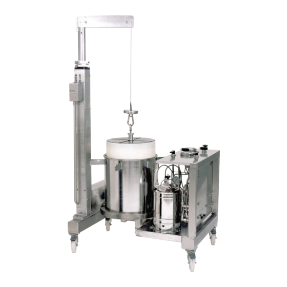
100 psig (6.9 bar). EPDM is resistant to polar Figure 2 . Flash 400 system. A = hoist, B = hoist control box, C = cartridge solvents but will swell in many common aliphatic and aromatic... - Page 5 4 = cartridge, 5 = O-ring “A” size 222, Chemraz, 6 = O-ring “B” size 223, Chemraz, 7 = top head assembly, 8 = cartridge seal adapter (adjustable), 9 = seal adapter housing (fixed), 10 = flow distribution plate (inside the cartridge), and 11 = frit. Flash 400 Part...
-
Page 6: Biotage Flash 400 Prepacked Cartridge
(PSV-03) that activates at pressures in excess of 125 psi (8.6 bar). Note: Biotage recommends using the same solvent for both the eluent and the radial compression fluid. Figure 5. The cartridge compression vent valve (MV-03) and the top vacuum break valve (MV-04) closed (left image) and opened (right image). -
Page 7: Control Panel
MV-01 MV-06 pressurized. PG-02 and PG-03 readings will equalize. Closes the valve. BIOTAGE FLASH 400 ® MV-08 Solvent pump valve. Turns the solvent pump on or off (O or I) by opening or closing the line between the air supply and the pump. -
Page 8: Side Connection Panel
Ensure that the cartridge Figure 9 . The side connection panel. tool outer ridge is fully engaged into the mating cartridge lifting groove. Re-tighten the knurled knob. Biotage Flash 400 User Manual | © Biotage 2018 ®... -
Page 9: Start-Up Kit
Ensure that the cartridge tool cannot be moved within the cartridge top. If the tool can be moved, loosen the knurled knob Biotage provides a start-up kit consisting of the following items: and repeat the tightening process to re-engage. Move the hoist arm so that the safety hook is centered over the Description cartridge tool and then fasten the hook to the tool’s eyebolt. -
Page 10: System Dimensions And Valves, Gauges, And Regulators
The bodies are stainless steel with Gauges, and Regulators glass lenses. All valves used on the Flash 400 system are fabricated from 316 For details about each component, see Figure 14 below, stainless steel with a PTFE seat and rated by the manufacturer Table 7 on page 9, and the Flash 400 flow diagram located to at least 200% of the maximum system working pressure. - Page 11 (PG-03) will be equal to the reading on the cartridge compression pressure gauge (PG-02). reservoir, which compresses the cartridge if the fluid reservoir is pressurized. PG-02 and PG-03 Table 7. Flash 400 valves, gauges, and regulators. readings will equalize. Closes the valve. MV-08 Solvent pump valve.
-
Page 12: Specifications
Formic acid (methanoic acid, HCOOH) » Acetic acid (Ethanoic acid, HOAc, AcOH) » Deionized water (H » Trifluoroacetic acid (TFA), max 5 % (by volume) » n-Heptane » Piperidine (pip) » Pyridine (pyr) Biotage Flash 400 User Manual | © Biotage 2018 ®... -
Page 13: Safety
Biotage. » Within limits set by the system’s technical specification and Only genuine Biotage spare parts must be used in the system. in line with user standard operating procedures (SOPs). Failure to follow those instructions and operate within the limits... -
Page 14: Safety Requirements
» The total weight of the package including the system is up to system is used in a manner not specified by Biotage, the 1043 kg (2300 lbs) depending on the system configuration. safety features of the system may be compromised. - Page 15 If any problems are the general atmosphere, contact Biotage for instructions found, solve them before using the equipment. »...
-
Page 16: Installation
(24") is required in front of the system to provide clearance for the range of motion of the Figure 15. Electrical ground stud location. hoist when inserting and removing cartridges. Biotage Flash 400 User Manual | © Biotage 2018 ®... -
Page 17: Gas Supply Connections
» Recommended Tubing Solvent Pump: Connect a compressed air supply to the Biotage recommends stainless steel or brass tubing or air port on the side connection panel (see Figure 16). stainless steel overbraided PTFE tubing for the gas supply Set the pressure to a maximum of 100 psig (6.9 bar). -
Page 18: Solvent Inlets (A And B)
= Solvent inlets on the side connection panel. Figure 18. The drain tube connected to the radial compression drain valve (MV-10) on the side connection panel is located underneath the Flash 400 frame, on the right side. Fraction Outlets (1 and 2) -
Page 19: Operation
Only use clamps, studs, nuts, and and the vacuum break valves (MV-04 and MV-05) are open; washers supplied by Biotage. see the instructions on page 27. 5. Remove the top head clamp by loosening the nuts on the sides 2. - Page 20 11. Slowly move the head assembly while attached to the hoist toward the front of the Flash 400 frame until it is completely 7. Move the hoist arm so that the safety hook is centered over clear of the frame and the radial compression module.
- Page 21 Operation 2. Move the cartridge shipping container holding the new cartridge next to the hoist. 3. Open the container and pull the plastic shipping bag away from the top of the cartridge. 4. Remove the sealing label at the top of the cartridge; see Figure 26.
- Page 22 8. Press and hold the button on the hoist control box until the head assembly has been lowered onto the radial compression barrel. Be sure to align the head assembly and barrel flange evenly as it is lowered. Biotage Flash 400 User Manual | © Biotage 2018 ®...
- Page 23 O-rings (see Figure 3 on page 3) and fulcrum arm; see Figure 30. retry, or contact Biotage 1-Point Support. 16. Inspect the head clamp. If the clamp, threaded studs, nuts, or washers show any sign of wear or damage, replace it/them.
-
Page 24: Fill The Radial Compression Fluid Reservoir
(MV-04) on the top head assembly; compression fluid. see Figure 35. Note: Biotage recommends using the same solvent for both the eluent and the radial compression fluid. 4. Install the lid on the radial compression fluid reservoir by tilting and lowering it into the mouth of the reservoir. -
Page 25: Test The Cartridge Sealing
Operation 4. Ensure that the bottom vacuum break and radial 12. Check for audible leaks, then turn the reservoir pressure compression drain valves (MV-05 and MV-10) on the side valve (MV-09) on the control panel to the position connection panel are closed. in-between vent and pressurize. -
Page 26: Test A Biotage Flash 400 Cartridge
Flash 400 Cartridge ® d. Check the gas pressure at the outlet 1 port and compare All new cartridges shipped from Biotage are guaranteed to it with the starting pressure reading. If the pressure perform according to specifications. Testing is optional, and is within 2 psig (0.1 bar) of the starting pressure, the... -
Page 27: Equilibrate The Cartridge
Operation Equilibrate the Cartridge Load the Sample Warning Warning » » Always equilibrate the cartridge. Take appropriate measures to protect against static discharge » by ensuring that the system and ancillary containers are Equilibrate the cartridge at a low flow rate to avoid extreme grounded (see page 14). -
Page 28: Purge And Flush The Cartridge
(i.e. repeat steps 1 through 5 above) before flushing with a new solvent. 6. Disconnect the gas supply from the three-way injection valve (MV-02) and reconnect the stainless steel overbraided solvent inlet tube. Biotage Flash 400 User Manual | © Biotage 2018 ®... -
Page 29: Depressurize And Drain The System
Operation Depressurize and Drain the System Warning » Only use waste containers that are grounded. » Ensure that the pump pressure gauge (PG-01) reads zero (0) bar/psig before disconnecting the stainless steel overbraided solvent inlet tube from the three-way injection valve. Note: Refer to Figure 14 on page 8 for component locations when performing this procedure. -
Page 30: Remove And Handle The Used Cartridge
The internal media is the previous step. inert except for extreme conditions. The most restricting factors in safe disposal are the substances that remain adsorbed or suspended on the media. Biotage Flash 400 User Manual | © Biotage 2018 ®... -
Page 31: Clean The System
Biotage safety and performance warranties. In addition 5. Inspect all O-rings. Ensure that they are not cut, flattened, this will yield a poorly performing cartridge and may cause or otherwise damaged. -
Page 32: Lock The Hoist In The Storage Position
28). 4. Re-install the clamp into the lower hole and lock it into position using the quick-release pins; see Figure 44. Figure 44. The hoist locked in the “storage”position. Biotage Flash 400 User Manual | © Biotage 2018 ®... -
Page 33: Troubleshooting
Clamp before the lubricating solvent evaporates. 2. The cartridge is too long. 2. Only use cartridges supplied by Biotage and of a length that corresponds to the radial compression module in use. 3. Bottom head assembly is out 3. -
Page 34: Radial Compression Fluid Reservoir
Set the nitrogen gas supply pressure to between 80 and 100 psig (5.5 to 6.9 bar). 2. Safety relief valve is defective. 2. Contact Biotage 1-Point Support; see contact information on the back of this document or visit our website www.biotage.com. Gas leaks around the top of 1. -
Page 35: General Information
US 6,139,733, US 6,294,087, US 6,221,252, and US 6,436,284. Price List and Ordering Information Please contact your Biotage distributor for the latest price and ordering information. Download User Documentation You can download the latest version of this document and other user documentation at www.biotage.com. -
Page 36: Appendix
Appendix Appendix Warranty and Liability Biotage Flash 400 Spare Parts ® See the “Biotage Terms & Conditions of Sale” document at Part No. Description www.biotage.com. 03020 Barrel O-Ring (D), 387 Viton Essential Tools List 03019 Barrel O-Ring (D), 387 EPDM... -
Page 37: Biotage
Appendix Biotage Flash 400 Process and Instrumentation Drawing ®... -
Page 38: Notes
Notes Notes Biotage Flash 400 User Manual | © Biotage 2018 ®... - Page 40 Part Number: 04149_EN-C © 2018 Biotage. All rights reserved. No material may be reproduced or published without the written permission of Biotage. Information in this document is subject to change without notice and does not represent any commitment from Biotage. E&OE.
Need help?
Do you have a question about the Flash 400 and is the answer not in the manual?
Questions and answers