
Related Manuals for Ludlum Measurements 375-31H


Summary of Contents for Ludlum Measurements 375-31H
- Page 1 LUDLUM MODELS 375-31H AREA MONITOR WITH NEUTRON DETECTOR January 2021 Serial Number 278020 and Succeeding Serial Numbers...
- Page 2 LUDLUM MODELS 375-31H AREA MONITOR WITH NEUTRON DETECTOR January 2021 Serial Number 278020 and Succeeding...
- Page 3 Models 375-31H Area Monitor with Neutron Detector Ludlum Measurements, Inc. January 2021...
- Page 4 RETURN OF GOODS TO MANUFACTURER If equipment needs to be returned to Ludlum Measurements, Inc. for repair or calibration, please send to the address below. All shipments should include documentation containing return shipping address, customer name, telephone number, description of service requested, and all other necessary information.
-
Page 6: Table Of Contents
Models 375-31H Area Monitor with Neutron Detector Table of Contents Introduction Getting Started Neutron Detector Power Up Checking Parameters *Model 375 Series One Setting Alarm Points Return for Repair and Calibration Specifications Area Monitor Detector Operator Controls and Setup Calibration Controls... - Page 7 Models 375-31H Area Monitor with Neutron Detector Analog Output Discriminator Battery Charge Calibrating Detector Operating Voltage Plateau Gamma Rejection Check Conversion Check Recycling Parts List Model 375 Digital Wall-Mount Area Monitor without Detector Model 375 Series One without Detector Main Board, Drawing 558 x 1...
-
Page 8: Introduction
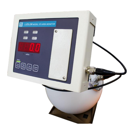
Section 1 Section Introduction he Model 375-31H Area Monitor with Neutron Detector is a versatile, compact, and easy-to-use digital electronic controller designed for monitoring radiation in areas. Its simple design accommodates many different detectors to suit a wide variety of applications, and it is equipped with a local readout and alarms. - Page 9 Models 375-31H Area Monitor with Neutron Detector The detector is fitted with a bracket to attach to the Model 375-31H. It consists of a cadmium-located polyethylene sphere surrounding the He detector. A study has demonstrated that the 9-inch cadmium-located sphere has a response similar to that of a 10-inch dimeter rem-responding sphere.
-
Page 10: Getting Started
Other sections of the manual provide more detailed information. Neutron Detector The Model 375-31H comes equipped with a neutron detector. The neutron detector is designed to detect thermal and fast neutrons (0.025 eV to approximately 12 MeV). Neutrons are detected indirectly through nuclear reactions, which result in energetically charged particles. -
Page 11: Power Up
Models 375-31H Area Monitor with Neutron Detector Section 2 Power Up Plug the wall-mount 9 Vdc power supply into a suitable wall (Mains) outlet. If the RS-232 feature is used, plug in a suitably wired 9-pin connector cable. (See Page 4-4 for the pin assignment of the 9-pin connector.) Turn power... -
Page 12: Model 375 Series One
Models 375-31H Area Monitor with Neutron Detector Section 2 : In the special case of the Model 375 Series One, Model 375 Series One make note of the following changes resulting from firmware modification: With the dipswitch in the left position, two decimal places will RANGE be displayed. -
Page 13: Specifications
Models 375-31H Area Monitor with Neutron Detector Section 3 Section Specifications Area Monitor Display : four-digit LED display with 2 cm (0.8 in.) character height Display Range : 000.0-9999 (Series One: 00.00-9999) Display Units : can be made to display in µR/hr, mR/hr, R/hr, µSv/h, mSv/h, Sv/h, µrem/hr, mrem/hr, rem/hr, cpm, cps, and others... - Page 14 Models 375-31H Area Monitor with Neutron Detector Section 3 : indicated by a red light and an audible tone greater than 68 dB DET Fail at 6.1 ft (2 m) for conditions of detector overload, no count from detector or instrument failure...
- Page 15 Models 375-31H Area Monitor with Neutron Detector Section 3 Relays: A 9-pin connector with male pins provides connection to three fail-safe form C relays, activated by the LOW ALARM (alert) High ALARM, and instrument FAIL. These contacts are potential-free (non- powered), but can handle 125 Vac at 0.3 A or 30 Vdc at 1 A.
-
Page 16: Detector
Models 375-31H Area Monitor with Neutron Detector Section 3 Detector 2 atm ³He tube LND 25185 or equivalent Detector: Moderator: 22.9 cm (9 in.) diameter cadmium-loaded polyethylene sphere Compatible Instruments: typically used with portable counting instruments (capable of achieving -2 mV input sensitivity) -
Page 17: Operator Controls And Setup
Models 375-31H Area Monitor with Neutron Detector Section 4 Section Operator Controls and Setup Calibration Controls Remove the calibration cover to expose the calibration controls. Warning! Do not touch the circuit board in the calibration window due to potential for electric shock. -
Page 18: Dipswitch (Under Calibration Cover)
Models 375-31H Area Monitor with Neutron Detector Section 4 : used to set the detector current overload point. When OVERLOAD excessive radiation causes the detector to overload, this set point will cause the light to engage, and the display will be forced to -... -
Page 19: 9-Pin Remote Data Connector
Models 375-31H Area Monitor with Neutron Detector Section 4 RS-232 Output With the dipswitch in the left position, the Model 375-31H CAL MODE dumps RS-232 data onto pin 4 of the 9-pin connector every two seconds. BYTE1 BYTE2 The RS-232 data includes the... -
Page 20: 9-Pin Relays Connector
Models 375-31H Area Monitor with Neutron Detector Section 4 9-Pin Relays Connector (male pins) The 9-pin relay connector provides a Form C (common, normally open, and normally closed) contact for the three fail-safe relays of LOW ALARM (alert), HIGH ALARM, and FAIL. -
Page 21: Common Options And Modifications
Models 375-31H Area Monitor with Neutron Detector Section 5 Section Common Options and Modifications Relay Options Internal Circuit-Board-Mounted Relays A 9-pin connector with male pins provides connection to three fail-safe form C relays, activiated by the LOW ALARM (alert), HIGH ALARM, and instrument FAIL. - Page 22 Models 375-31H Area Monitor with Neutron Detector Section 5 External Mains (120 or 240 VAC) Alarm Relay Out (using 3 pin connector) PN4558-038 Allows the use of the 9-pin D female connector for RS-232 or remote use and does not interfere with the internal form C relays.
- Page 23 Models 375-31H Area Monitor with Neutron Detector Section 5 Figure 2. Mains Relay Box Front Panel. See below for description of noted parts in drawing above. A – conduit connector to the box if necessary. B – AC receptacle (removed if using conduit).
- Page 24 Models 375-31H Area Monitor with Neutron Detector Section 5 Figure 3. Mains Relay Box Inside View. See below for description of noted parts in drawing above. A – 110/220 Vac conduit AC input. “H” = hot and “N” = neutral. For 220 Vac, H = L1 and N = L2.
-
Page 25: Ethernet Interface Option
RS-232 port. The Model ALARM FAIL 375-31H will print once every 30 seconds as long as the alarm or fail condition is present. Setup You will need the following: a Model 375-31H instrument, a CBM-910 40-column printer, and a cable (8558-142). -
Page 26: Printer Dip Switch Settings
Models 375-31H Area Monitor with Neutron Detector Section 5 RS-232 Data Format The data will be sent to the RS-232 port as: Byte 1 Byte 18 Space (20H) Byte 2 Byte 19 Byte 3 x OR x Byte 20 Byte 4... -
Page 27: Sigma Alarm Modification Option
60 seconds after the Model 375-31H is turned , in order to allow the Model 375-31H to accumulate a stable background radiation reading. Two other changes were made to the Model 375-31H. The first change was to deactivate the indicator. Both the sigma-based alarm (set by... -
Page 28: To 20 Ma Isolated Output Driver Option
4 to 20 mA Isolated Output Driver Option 4 to 20 mA Driver (Isolated) Modification Kit Part Number 4558-104 This circuit may be added to replace the Model 375-31H analog output, providing an isolated 4 to 20 mA output capability. - Page 29 Models 375-31H Area Monitor with Neutron Detector Section 5 For Series One: Decade “Base” Display mA Value 0.01 4 mA 0.10 7.2 mA 1.00 10.4 mA 10.00 13.6 mA 16.8 mA 1000 20 mA mA value = �������������� �������������� 4 ���� + (3.2 ���� ∗ Decade) + 3.2 log ( ��������...
- Page 30 Models 375-31H Area Monitor with Neutron Detector Section 5 Internal Board Header Pinout P1-1) Loop GND (Isolated) P1-2) 4-20 current output (Isolated) P2-1) +7.5 Vdc , RAWDC from main circuit board number 5396-160 (May range from +5.5 to 15 Vdc)
-
Page 31: Safety Considerations
Pollution Degree 2 (as defined by IEC 664) Cleaning Instructions and Precautions The Model 375-31H may be cleaned externally with bleach wipes or with a damp cloth, using water, Lysol or alcohol as a wetting agent. Do not immerse the instrument in any liquid. Observe the following precautions when cleaning: 1. -
Page 32: Warning Markings And Symbols
Ludlum Measurements, Inc. The Model 375-31H is marked with the following symbols: CAUTION, RISK OF ELECTRIC SHOCK (per ISO 3864, No. B.3.6) – designates a terminal (connector) that allows connection to a voltage exceeding 1 kV. -
Page 33: Electrical Safety Precautions
Models 375-31H Area Monitor with Neutron Detector Section 6 Warning! The operator is strongly cautioned to take the following precautions to avoid contact with internal hazardous live parts that are accessible using a tool: 1. Turn the instrument power and disconnect the power cord. -
Page 34: Detector Connector
Models 375-31H Area Monitor with Neutron Detector Section 6 result in the unit falling down and causing personal injury and/or property damage. Detector Connector Warning! Potential electrical shock hazard: do not touch the center pin of the detector connector unless the unit has turned off and power has been removed for at least one minute. -
Page 35: Calibration
Models 375-31H Area Monitor with Neutron Detector Section 7 Section Calibration High Voltage The high voltage is adjustable from 450-2500 Vdc using the potentiometer located under the calibration cover. The high voltage required will depend on the type of detector used. Internal GM detectors usually require 550 Vdc. -
Page 36: Analog Output
Models 375-31H Area Monitor with Neutron Detector Section 7 The dead time correction ( ) is set when the detector is exposed to a DEAD TIME "high" radiation field. A "high" radiation field in this case is defined as a field where dead time losses exceed 30%. -
Page 37: Battery Charge
Models 375-31H Area Monitor with Neutron Detector Section 7 Battery Charge The potentiometer labeled , located under the calibration cover, is used to set the backup battery trickle-charge voltage. This is typically set to 6.9 Vdc with the battery disconnected. -
Page 38: Gamma Rejection Check
Models 375-31H Area Monitor with Neutron Detector Section 7 For example, an assumed operating voltage is 1100 volts, based upon the flattest part of the plateau. The count rate at that voltage is 2380 counts per minute (cpm), and the neutron field dose-equivalent rate is 20 mrem/hr. - Page 39 Models 375-31H Area Monitor with Neutron Detector Section 7 Ref. Point Reading Range/ (mrem/hr) (cpm) Scale Ludlum Measurements, Inc. Page 7-5 January 2021...
-
Page 40: Recycling
To this end, Ludlum Measurements, Inc. strives to supply the consumer of its goods with information regarding reuse and recycling of the many different types of materials used in its products. With many different agencies –... -
Page 41: Parts List
Models 375-31H Area Monitor with Neutron Detector Section 9 Section Parts List Reference Description Part Number Model 375 Digital Wall- UNIT Completely Assembled 48-2230 Mount Area Monitor Model 375 without Detector UNIT Completely Assembled 48-2676 Model 375 Series One Model 375 Series One... - Page 42 Models 375-31H Area Monitor with Neutron Detector Section 9 Reference Description Part Number C201 10µF, 25V 04-5655 C211 27pF, 100V 04-5658 C221 100µF, 16V 04-5794 C222 27pF, 100V 04-5658 C301-C303 10µF, 25V 04-5655 C401 100µF, 16V 04-5794 C441-C442 100µF, 16V...
- Page 43 Models 375-31H Area Monitor with Neutron Detector Section 9 Reference Description Part Number U233 SA08-11EWA 07-6389 U241 KB-2685EW 07-6400 U251 TLC372IDR 06-6290 U321 M24C02-WMN6TP 06-6299 U331 ICL7663SCBAZA-T 06-6302 U411 P89V51RD2FA 06-6303 U521 CD74HC4538M96 06-6297 U531 OPA2343UA2K5 06-6582 U611 MAX985EUK+T 06-6459...
- Page 44 Models 375-31H Area Monitor with Neutron Detector Section 9 Reference Description Part Number POTENTIOMETER 1M, BAT CHG ADJ 09-6778 1M, HV ADJ 09-6778 R523 1M, OVLD ADJ 09-6778 R535 200K, THR ADJ 09-6949 R537 5K, RCDR 09-6849 RESISTORS R1-R4 301ohm, 1%, 250mW...
- Page 45 Models 375-31H Area Monitor with Neutron Detector Section 9 Reference Description Part Number R533 10K, 1%, 250mW 12-7839 R534 2.21K, 1%, 250mW 12-7835 R611 47.5K, 1%, 250mW 12-7872 R621 4.75K, 1%, 250mW 12-7858 R622 10K, 1%, 250mW 12-7839 R623 1K, 1%, 250mW...
- Page 46 Models 375-31H Area Monitor with Neutron Detector Section 9 Reference Description Part Number RELAY RL1-RL3 G6K-2FY DC5 22-9332 TRANSFORMER 32377R 21-9925 MISCELLANEOUS SOCKET 44P PLCC 06-6613 SHIELD-M4500 PREAMP 7436-142 RABBIT RCM 3700 23110915 COAX, WIRE W3-W5 WIRE TP1-TP3 COAX, WIRE...
-
Page 47: Wiring Diagram, Drawing 558 X 136
Models 375-31H Area Monitor with Neutron Detector Section 10 Section Drawings Main Circuit Board, Drawing 558 x 1 (5 sheets) Main Circuit Board Component Layout Drawing 558 x 2A (2 sheets) Wiring Diagram, Drawing 558 x 136 Ludlum Measurements, Inc.
Need help?
Do you have a question about the 375-31H and is the answer not in the manual?
Questions and answers